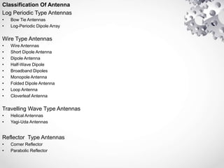
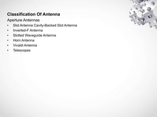
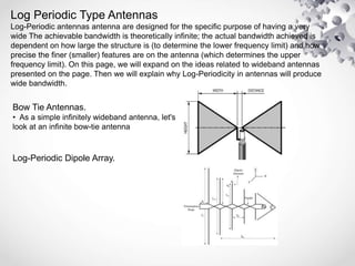
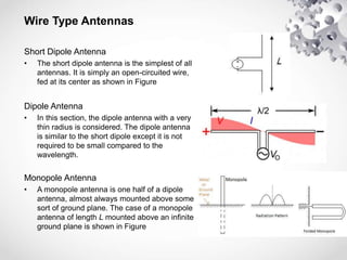
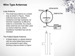
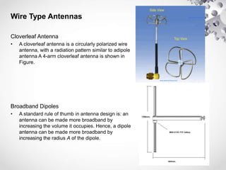
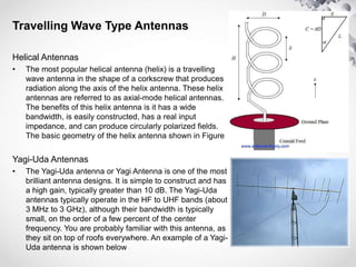
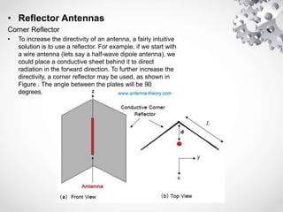
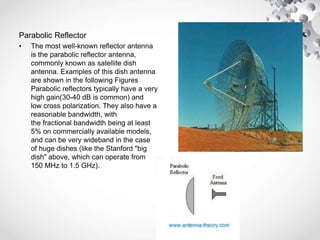
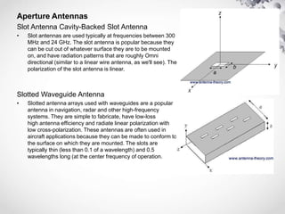
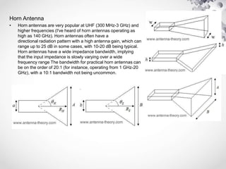
Classification Of Antenna
B.E Semester 6th
(E.C Department)
Enroll No. Name.
150600111012 Kashif Khan
Antenna
What is Antenna?
• An antenna is a transducer that converts radio frequency (RF) fields into
alternating current or vice versa. There are both receiving and
transmission antennas for sending or receiving radio transmissions.
Classification Of Antenna
• Log Periodic Antennas
• Wire Antennas
• Travelling Wave Antennas
• Microwave Antennas
• Reflector Antennas
Classification Of Antenna
Log Periodic Type Antennas
• Bow Tie Antennas
• Log-Periodic Dipole Array
Wire Type Antennas
• Wire Antennas
• Short Dipole Antenna
• Dipole Antenna
• Half-Wave Dipole
• Broadband Dipoles
• Monopole Antenna
• Folded Dipole Antenna
• Loop Antenna
• Cloverleaf Antenna
Travelling Wave Type Antennas
• Helical Antennas
• Yagi-Uda Antennas
Reflector Type Antennas
• Corner Reflector
• Parabolic Reflector
Classification Of Antenna
Aperture Antennas
• Slot Antenna Cavity-Backed Slot Antenna
• Inverted-F Antenna
• Slotted Waveguide Antenna
• Horn Antenna
• Vivaldi Antenna
• Telescopes
Log Periodic Type Antennas
Log-Periodic antennas antenna are designed for the specific purpose of having a very
wide The achievable bandwidth is theoretically infinite; the actual bandwidth achieved is
dependent on how large the structure is (to determine the lower frequency limit) and how
precise the finer (smaller) features are on the antenna (which determines the upper
frequency limit). On this page, we will expand on the ideas related to wideband antennas
presented on the page. Then we will explain why Log-Periodicity in antennas will produce
wide bandwidth.
Bow Tie Antennas.
• As a simple infinitely wideband antenna, let's
look at an infinite bow-tie antenna
Log-Periodic Dipole Array.
Wire Type Antennas
Short Dipole Antenna
• The short dipole antenna is the simplest of all
antennas. It is simply an open-circuited wire,
fed at its center as shown in Figure
Dipole Antenna
• In this section, the dipole antenna with a very
thin radius is considered. The dipole antenna
is similar to the short dipole except it is not
required to be small compared to the
wavelength.
Monopole Antenna
• A monopole antenna is one half of a dipole
antenna, almost always mounted above some
sort of ground plane. The case of a monopole
antenna of length L mounted above an infinite
ground plane is shown in Figure
Wire Type Antennas
Loop Antenna
• The small loop antenna is a closed
loop as shown in Figure . These
antennas have low radiation
resistance and high reactance, so
that their impedance is difficult to
match to a transmitter. As a result,
these antennas are most often used
as receive antennas, where
impedance mismatch loss can be
tolerated.
The Folded Dipole Antenna
• A folded dipole is a dipole antenna
with the ends folded back around
and connected to each other,
forming a loop as shown in Figure
Wire Type Antennas
Cloverleaf Antenna
• A cloverleaf antenna is a circularly polarized wire
antenna, with a radiation pattern similar to adipole
antenna A 4-arm cloverleaf antenna is shown in
Figure.
Broadband Dipoles
• A standard rule of thumb in antenna design is: an
antenna can be made more broadband by
increasing the volume it occupies. Hence, a dipole
antenna can be made more broadband by
increasing the radius A of the dipole.
Travelling Wave Type Antennas
Helical Antennas
• The most popular helical antenna (helix) is a travelling
wave antenna in the shape of a corkscrew that produces
radiation along the axis of the helix antenna. These helix
antennas are referred to as axial-mode helical antennas.
The benefits of this helix antenna is it has a wide
bandwidth, is easily constructed, has a real input
impedance, and can produce circularly polarized fields.
The basic geometry of the helix antenna shown in Figure
Yagi-Uda Antennas
• The Yagi-Uda antenna or Yagi Antenna is one of the most
brilliant antenna designs. It is simple to construct and has
a high gain, typically greater than 10 dB. The Yagi-Uda
antennas typically operate in the HF to UHF bands (about
3 MHz to 3 GHz), although their bandwidth is typically
small, on the order of a few percent of the center
frequency. You are probably familiar with this antenna, as
they sit on top of roofs everywhere. An example of a Yagi-
Uda antenna is shown below
• Reflector Antennas
Corner Reflector
• To increase the directivity of an antenna, a fairly intuitive
solution is to use a reflector. For example, if we start with
a wire antenna (lets say a half-wave dipole antenna), we
could place a conductive sheet behind it to direct
radiation in the forward direction. To further increase the
directivity, a corner reflector may be used, as shown in
Figure . The angle between the plates will be 90
degrees.
Parabolic Reflector
• The most well-known reflector antenna
is the parabolic reflector antenna,
commonly known as satellite dish
antenna. Examples of this dish antenna
are shown in the following Figures
Parabolic reflectors typically have a very
high gain(30-40 dB is common) and
low cross polarization. They also have a
reasonable bandwidth, with
the fractional bandwidth being at least
5% on commercially available models,
and can be very wideband in the case
of huge dishes (like the Stanford "big
dish" above, which can operate from
150 MHz to 1.5 GHz).
Aperture Antennas
Slot Antenna Cavity-Backed Slot Antenna
• Slot antennas are used typically at frequencies between 300
MHz and 24 GHz. The slot antenna is popular because they
can be cut out of whatever surface they are to be mounted
on, and have radiation patterns that are roughly Omni
directional (similar to a linear wire antenna, as we'll see). The
polarization of the slot antenna is linear.
Slotted Waveguide Antenna
• Slotted antenna arrays used with waveguides are a popular
antenna in navigation, radar and other high-frequency
systems. They are simple to fabricate, have low-loss
high antenna efficiency and radiate linear polarization with
low cross-polarization. These antennas are often used in
aircraft applications because they can be made to conform to
the surface on which they are mounted. The slots are
typically thin (less than 0.1 of a wavelength) and 0.5
wavelengths long (at the center frequency of operation.
Horn Antenna
• Horn antennas are very popular at UHF (300 MHz-3 GHz) and
higher frequencies (I've heard of horn antennas operating as
high as 140 GHz). Horn antennas often have a
directional radiation pattern with a high antenna gain, which can
range up to 25 dB in some cases, with 10-20 dB being typical.
Horn antennas have a wide impedance bandwidth, implying
that the input impedance is slowly varying over a wide
frequency range The bandwidth for practical horn antennas can
be on the order of 20:1 (for instance, operating from 1 GHz-20
GHz), with a 10:1 bandwidth not being uncommon.
Thank you

Classification of antenna

  • 1.
    Classification Of Antenna B.ESemester 6th (E.C Department) Enroll No. Name. 150600111012 Kashif Khan
  • 2.
    Antenna What is Antenna? •An antenna is a transducer that converts radio frequency (RF) fields into alternating current or vice versa. There are both receiving and transmission antennas for sending or receiving radio transmissions. Classification Of Antenna • Log Periodic Antennas • Wire Antennas • Travelling Wave Antennas • Microwave Antennas • Reflector Antennas
  • 3.
    Classification Of Antenna LogPeriodic Type Antennas • Bow Tie Antennas • Log-Periodic Dipole Array Wire Type Antennas • Wire Antennas • Short Dipole Antenna • Dipole Antenna • Half-Wave Dipole • Broadband Dipoles • Monopole Antenna • Folded Dipole Antenna • Loop Antenna • Cloverleaf Antenna Travelling Wave Type Antennas • Helical Antennas • Yagi-Uda Antennas Reflector Type Antennas • Corner Reflector • Parabolic Reflector
  • 4.
    Classification Of Antenna ApertureAntennas • Slot Antenna Cavity-Backed Slot Antenna • Inverted-F Antenna • Slotted Waveguide Antenna • Horn Antenna • Vivaldi Antenna • Telescopes
  • 5.
    Log Periodic TypeAntennas Log-Periodic antennas antenna are designed for the specific purpose of having a very wide The achievable bandwidth is theoretically infinite; the actual bandwidth achieved is dependent on how large the structure is (to determine the lower frequency limit) and how precise the finer (smaller) features are on the antenna (which determines the upper frequency limit). On this page, we will expand on the ideas related to wideband antennas presented on the page. Then we will explain why Log-Periodicity in antennas will produce wide bandwidth. Bow Tie Antennas. • As a simple infinitely wideband antenna, let's look at an infinite bow-tie antenna Log-Periodic Dipole Array.
  • 6.
    Wire Type Antennas ShortDipole Antenna • The short dipole antenna is the simplest of all antennas. It is simply an open-circuited wire, fed at its center as shown in Figure Dipole Antenna • In this section, the dipole antenna with a very thin radius is considered. The dipole antenna is similar to the short dipole except it is not required to be small compared to the wavelength. Monopole Antenna • A monopole antenna is one half of a dipole antenna, almost always mounted above some sort of ground plane. The case of a monopole antenna of length L mounted above an infinite ground plane is shown in Figure
  • 7.
    Wire Type Antennas LoopAntenna • The small loop antenna is a closed loop as shown in Figure . These antennas have low radiation resistance and high reactance, so that their impedance is difficult to match to a transmitter. As a result, these antennas are most often used as receive antennas, where impedance mismatch loss can be tolerated. The Folded Dipole Antenna • A folded dipole is a dipole antenna with the ends folded back around and connected to each other, forming a loop as shown in Figure
  • 8.
    Wire Type Antennas CloverleafAntenna • A cloverleaf antenna is a circularly polarized wire antenna, with a radiation pattern similar to adipole antenna A 4-arm cloverleaf antenna is shown in Figure. Broadband Dipoles • A standard rule of thumb in antenna design is: an antenna can be made more broadband by increasing the volume it occupies. Hence, a dipole antenna can be made more broadband by increasing the radius A of the dipole.
  • 9.
    Travelling Wave TypeAntennas Helical Antennas • The most popular helical antenna (helix) is a travelling wave antenna in the shape of a corkscrew that produces radiation along the axis of the helix antenna. These helix antennas are referred to as axial-mode helical antennas. The benefits of this helix antenna is it has a wide bandwidth, is easily constructed, has a real input impedance, and can produce circularly polarized fields. The basic geometry of the helix antenna shown in Figure Yagi-Uda Antennas • The Yagi-Uda antenna or Yagi Antenna is one of the most brilliant antenna designs. It is simple to construct and has a high gain, typically greater than 10 dB. The Yagi-Uda antennas typically operate in the HF to UHF bands (about 3 MHz to 3 GHz), although their bandwidth is typically small, on the order of a few percent of the center frequency. You are probably familiar with this antenna, as they sit on top of roofs everywhere. An example of a Yagi- Uda antenna is shown below
  • 10.
    • Reflector Antennas CornerReflector • To increase the directivity of an antenna, a fairly intuitive solution is to use a reflector. For example, if we start with a wire antenna (lets say a half-wave dipole antenna), we could place a conductive sheet behind it to direct radiation in the forward direction. To further increase the directivity, a corner reflector may be used, as shown in Figure . The angle between the plates will be 90 degrees.
  • 11.
    Parabolic Reflector • Themost well-known reflector antenna is the parabolic reflector antenna, commonly known as satellite dish antenna. Examples of this dish antenna are shown in the following Figures Parabolic reflectors typically have a very high gain(30-40 dB is common) and low cross polarization. They also have a reasonable bandwidth, with the fractional bandwidth being at least 5% on commercially available models, and can be very wideband in the case of huge dishes (like the Stanford "big dish" above, which can operate from 150 MHz to 1.5 GHz).
  • 12.
    Aperture Antennas Slot AntennaCavity-Backed Slot Antenna • Slot antennas are used typically at frequencies between 300 MHz and 24 GHz. The slot antenna is popular because they can be cut out of whatever surface they are to be mounted on, and have radiation patterns that are roughly Omni directional (similar to a linear wire antenna, as we'll see). The polarization of the slot antenna is linear. Slotted Waveguide Antenna • Slotted antenna arrays used with waveguides are a popular antenna in navigation, radar and other high-frequency systems. They are simple to fabricate, have low-loss high antenna efficiency and radiate linear polarization with low cross-polarization. These antennas are often used in aircraft applications because they can be made to conform to the surface on which they are mounted. The slots are typically thin (less than 0.1 of a wavelength) and 0.5 wavelengths long (at the center frequency of operation.
  • 13.
    Horn Antenna • Hornantennas are very popular at UHF (300 MHz-3 GHz) and higher frequencies (I've heard of horn antennas operating as high as 140 GHz). Horn antennas often have a directional radiation pattern with a high antenna gain, which can range up to 25 dB in some cases, with 10-20 dB being typical. Horn antennas have a wide impedance bandwidth, implying that the input impedance is slowly varying over a wide frequency range The bandwidth for practical horn antennas can be on the order of 20:1 (for instance, operating from 1 GHz-20 GHz), with a 10:1 bandwidth not being uncommon.
  • 14.