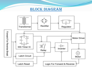
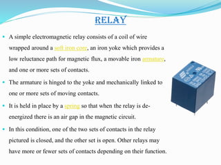
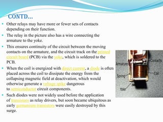
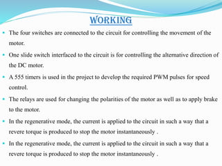
FOUR QUADRENT DC MOTOR
Under the Guidance of
Er. Rajendra Kumar
Submitted by
Ashish Singh (1600420003)
Avinash Kr. Vishwakarma (1600420004)
Deepak Kushwah (1600420005)
Kashif (1600420009)
Project Title
1. ABSTARCT
2. BLOCK DIAGRAM
3. HARDWARE COMPONENTS
4. BC457 TRANSISTOR
5. IC 555 TIMER
6. LED
7. 1N4007 DIODES
8. RESISTOR
9. RELAY
10. CAPACITOR
11. VOLTAGE TRANSFORMER
12. WORKING
13. ADVANTAGE
ABSTARCT
 The main intention of this project is to control the speed of a DC motor in
alternative directions using speed control unit and to operate the motor in
four quadrants: ie, clockwise, counter clock-wise, forward brake and reverse
brake.
 This system uses an H-bridge motor drive IC for controlling the DC motor
from corresponding switches used by the user for pressing.
 The four switches are connected to the circuit for controlling the movement
of the motor.
 One slide switch interfaced to the circuit is for controlling the alternative
direction of the DC motor.
 A 555 timers is used in the project to develop the required PWM pulses for
speed control.
CONTD…
 The relays are used for changing the polarities of the motor as well as to
apply brake to the motor. In the regenerative mode, the current is applied
to the circuit in such a way that a revere torque is produced to stop the
motor instantaneously .
 The four-quadrant control of the DC motor is archived by the varying
duty cycles from a 555 timer and their changing polarity with the H-
bridge IC by appropriate switch pressing. The alternative speed control
feature is achieved by a slide switch operation.
 This project in future can be improved by using higher-power electronic
devices to operate high- capacity DC motors. Regenerative braking for
optimizing the power consumption can also be incorporated.
BLOCK DIAGRAM
 IC-555
 IC-Z44
 Transistor
 LED
 Diode
 Resistor
 Relay
 Capacitor
 Switches
 Transformer
HARDWARE COMPONENTS
BC547
The BC547 transistor is an NPN Epitaxial
Silicon Transistor.
The BC547 transistor is a general-purpose
transistor in small plastic packages.
 It is used in general-purpose switching and
amplification BC847/BC547 series 45 V, 100 mA
NPN general-purpose transistors.
Whenever base is high, then current starts
flowing through base and emitter and after that
only current will pass from collector to emitter
IC-555
 IC 555 timer is a well-known component in the electronic circles but
what is not known to most of the people is the internal circuitry of the
IC and the function of various pins present there in the IC.
 Let me tell you a fact about why 555 timer is called so, the timer got
its name from the three 5 kilo-ohm resistor in series employed in the
internal circuit of the IC.
 IC 555 timer is a one of the most widely used IC in electronics and is
used in various electronic circuits for its robust and stable properties.
 It works as square-wave form generator with duty cycle varying from
50% to 100%, Oscillator and can also provide time delay in circuits.
 The 555 timer got its name from the three 5k ohm resistor connected
in a voltage-divider pattern which is shown in the figure below.
 A simplified diagram of the internal circuit is given below for better
understanding as the full internal circuit consists of over more than 16
resistors, 20 transistors, 2 diodes, a flip-flop and many other circuit
components.
CONTD…
 The 555 timer comes as 8 pin DIP
(Dual In-line Package) device.
 There is also a 556 dual version
of 555 timer which consists of
two complete 555 timers in 14
DIP and a 558 quadruple timer
which is consisting of four 555
timer in one IC and is available as
a 16 pin DIP in the market.
LED
 LEDs are semiconductor devices.
 Like transistors, and other diodes, LEDs are made out of
silicon.
 What makes an LED give off light are the small amounts of
chemical impurities that are added to the silicon, such as
gallium, arsenide, indium, and nitride.
 When current passes through the LED, it emits photons as a
byproduct.
 Normal light bulbs produce light by heating a metal filament
until its white hot.
CONTD…
 When the diode is forward biased (switched
on), electrons are able to recombine with holes
and energy is released in the form of light.
 This effect is called electroluminescence and
the color of the light is determined by the
energy gap of the semiconductor.
 The LED is usually small in area (less than 1
mm2) with integrated optical components to
shape its radiation pattern and assist in
reflection.
1N4007
 Diodes are used to convert AC into DC
these are used as half wave rectifier or full
wave rectifier.
 Three points must he kept in mind while
using any type of diode.
a. Maximum forward current capacity
b. Maximum reverse voltage capacity
c. Maximum forward voltage capacity
CONTD…
 Diode of same capacities can be used in place of one another.
 Besides this diode of more capacity can be used in place of diode of low capacity but
diode of low capacity cannot be used in place of diode of high capacity.
 For example, in place of IN4002; IN4001 or IN4007 can be used but IN4001 or
IN4002 cannot be used in place of IN4007.
 The diode BY125made by company BEL is equivalent of diode from IN4001 to
IN4003.
 BY 126 is equivalent to diodes IN4004 to 4006 and BY 127 is equivalent to diode
IN4007.
RESISTORS
 A resistor is a two-terminal electronic component designed
to oppose an electric current by producing a voltage drop
between its terminals in proportion to the current, that is,
in accordance with Ohm's law:
V = IR
 Resistors are used as part of electrical networks and
electronic circuits. They are extremely commonplace in
most electronic equipment.
 Practical resistors can be made of various compounds and
films, as well as resistance wire (wire made of a high-
resistivity alloy, such as nickel/chrome).
RELAY
 A simple electromagnetic relay consists of a coil of wire
wrapped around a soft iron core, an iron yoke which provides a
low reluctance path for magnetic flux, a movable iron armature,
and one or more sets of contacts.
 The armature is hinged to the yoke and mechanically linked to
one or more sets of moving contacts.
 It is held in place by a spring so that when the relay is de-
energized there is an air gap in the magnetic circuit.
 In this condition, one of the two sets of contacts in the relay
pictured is closed, and the other set is open. Other relays may
have more or fewer sets of contacts depending on their function.
CONTD…
 Other relays may have more or fewer sets of contacts
depending on their function.
 The relay in the picture also has a wire connecting the
armature to the yoke.
 This ensures continuity of the circuit between the moving
contacts on the armature, and the circuit track on the printed
circuit board (PCB) via the yoke, which is soldered to the
PCB.
 When the coil is energized with direct current, a diode is often
placed across the coil to dissipate the energy from the
collapsing magnetic field at deactivation, which would
otherwise generate a voltage spike dangerous
to semiconductor circuit components.
 Such diodes were not widely used before the application
of transistors as relay drivers, but soon became ubiquitous as
early germanium transistors were easily destroyed by this
surge.
CAPACITORS
 A capacitor or condenser is a passive electronic
component consisting of a pair of conductors
separated by a dielectric.
 When a voltage potential difference exists
between the conductors, an electric field is
present in the dielectric.
 This field stores energy and produces a
mechanical force between the plates.
 The effect is greatest between wide, flat,
parallel, narrowly separated conductors.
Voltage Transformer
 One of the main reasons that we use alternating AC
voltages and currents in our homes and workplace’s
is that AC supplies can be easily generated at a
convenient voltage, transformed (hence the name
transformer) into much higher voltages and then
distributed.
 The reason for transforming the voltage to a much
higher level is that higher distribution voltages
implies lower currents for the same power and
therefore lower I2R losses along the networked grid
of cables.
 These higher AC transmission voltages and currents
can then be reduced to a much lower, safer and usable
voltage level where it can be used to supply electrical
equipment in our homes and workplaces, and all this
is possible thanks to the basic Voltage Transformer.
CONTD…
 The Voltage Transformer can be
thought of as an electrical
component rather than an electronic
component.
 A transformer basically is very
simple static (or stationary) electro-
magnetic passive electrical device
that works on the principle of
Faraday’s law of induction by
converting electrical energy from
one value to another.
WORKING
 The four switches are connected to the circuit for controlling the movement of the
motor.
 One slide switch interfaced to the circuit is for controlling the alternative direction of
the DC motor.
 A 555 timers is used in the project to develop the required PWM pulses for speed
control.
 The relays are used for changing the polarities of the motor as well as to apply brake
to the motor.
 In the regenerative mode, the current is applied to the circuit in such a way that a
revere torque is produced to stop the motor instantaneously .
 In the regenerative mode, the current is applied to the circuit in such a way that a
revere torque is produced to stop the motor instantaneously .
ADVANTAGE
 A 555 timers is used in the project to develop the required PWM pulses for speed
control.
 The alternative speed control feature is achieved by a slide switch operation.
Four Quadrent DC Motor .pdf

Four Quadrent DC Motor .pdf

  • 1.
    FOUR QUADRENT DCMOTOR Under the Guidance of Er. Rajendra Kumar Submitted by Ashish Singh (1600420003) Avinash Kr. Vishwakarma (1600420004) Deepak Kushwah (1600420005) Kashif (1600420009) Project Title
  • 2.
    1. ABSTARCT 2. BLOCKDIAGRAM 3. HARDWARE COMPONENTS 4. BC457 TRANSISTOR 5. IC 555 TIMER 6. LED 7. 1N4007 DIODES 8. RESISTOR 9. RELAY 10. CAPACITOR 11. VOLTAGE TRANSFORMER 12. WORKING 13. ADVANTAGE
  • 3.
    ABSTARCT  The mainintention of this project is to control the speed of a DC motor in alternative directions using speed control unit and to operate the motor in four quadrants: ie, clockwise, counter clock-wise, forward brake and reverse brake.  This system uses an H-bridge motor drive IC for controlling the DC motor from corresponding switches used by the user for pressing.  The four switches are connected to the circuit for controlling the movement of the motor.  One slide switch interfaced to the circuit is for controlling the alternative direction of the DC motor.  A 555 timers is used in the project to develop the required PWM pulses for speed control.
  • 4.
    CONTD…  The relaysare used for changing the polarities of the motor as well as to apply brake to the motor. In the regenerative mode, the current is applied to the circuit in such a way that a revere torque is produced to stop the motor instantaneously .  The four-quadrant control of the DC motor is archived by the varying duty cycles from a 555 timer and their changing polarity with the H- bridge IC by appropriate switch pressing. The alternative speed control feature is achieved by a slide switch operation.  This project in future can be improved by using higher-power electronic devices to operate high- capacity DC motors. Regenerative braking for optimizing the power consumption can also be incorporated.
  • 5.
  • 6.
     IC-555  IC-Z44 Transistor  LED  Diode  Resistor  Relay  Capacitor  Switches  Transformer HARDWARE COMPONENTS
  • 7.
    BC547 The BC547 transistoris an NPN Epitaxial Silicon Transistor. The BC547 transistor is a general-purpose transistor in small plastic packages.  It is used in general-purpose switching and amplification BC847/BC547 series 45 V, 100 mA NPN general-purpose transistors. Whenever base is high, then current starts flowing through base and emitter and after that only current will pass from collector to emitter
  • 8.
    IC-555  IC 555timer is a well-known component in the electronic circles but what is not known to most of the people is the internal circuitry of the IC and the function of various pins present there in the IC.  Let me tell you a fact about why 555 timer is called so, the timer got its name from the three 5 kilo-ohm resistor in series employed in the internal circuit of the IC.  IC 555 timer is a one of the most widely used IC in electronics and is used in various electronic circuits for its robust and stable properties.  It works as square-wave form generator with duty cycle varying from 50% to 100%, Oscillator and can also provide time delay in circuits.  The 555 timer got its name from the three 5k ohm resistor connected in a voltage-divider pattern which is shown in the figure below.  A simplified diagram of the internal circuit is given below for better understanding as the full internal circuit consists of over more than 16 resistors, 20 transistors, 2 diodes, a flip-flop and many other circuit components.
  • 9.
    CONTD…  The 555timer comes as 8 pin DIP (Dual In-line Package) device.  There is also a 556 dual version of 555 timer which consists of two complete 555 timers in 14 DIP and a 558 quadruple timer which is consisting of four 555 timer in one IC and is available as a 16 pin DIP in the market.
  • 10.
    LED  LEDs aresemiconductor devices.  Like transistors, and other diodes, LEDs are made out of silicon.  What makes an LED give off light are the small amounts of chemical impurities that are added to the silicon, such as gallium, arsenide, indium, and nitride.  When current passes through the LED, it emits photons as a byproduct.  Normal light bulbs produce light by heating a metal filament until its white hot.
  • 11.
    CONTD…  When thediode is forward biased (switched on), electrons are able to recombine with holes and energy is released in the form of light.  This effect is called electroluminescence and the color of the light is determined by the energy gap of the semiconductor.  The LED is usually small in area (less than 1 mm2) with integrated optical components to shape its radiation pattern and assist in reflection.
  • 12.
    1N4007  Diodes areused to convert AC into DC these are used as half wave rectifier or full wave rectifier.  Three points must he kept in mind while using any type of diode. a. Maximum forward current capacity b. Maximum reverse voltage capacity c. Maximum forward voltage capacity
  • 13.
    CONTD…  Diode ofsame capacities can be used in place of one another.  Besides this diode of more capacity can be used in place of diode of low capacity but diode of low capacity cannot be used in place of diode of high capacity.  For example, in place of IN4002; IN4001 or IN4007 can be used but IN4001 or IN4002 cannot be used in place of IN4007.  The diode BY125made by company BEL is equivalent of diode from IN4001 to IN4003.  BY 126 is equivalent to diodes IN4004 to 4006 and BY 127 is equivalent to diode IN4007.
  • 14.
    RESISTORS  A resistoris a two-terminal electronic component designed to oppose an electric current by producing a voltage drop between its terminals in proportion to the current, that is, in accordance with Ohm's law: V = IR  Resistors are used as part of electrical networks and electronic circuits. They are extremely commonplace in most electronic equipment.  Practical resistors can be made of various compounds and films, as well as resistance wire (wire made of a high- resistivity alloy, such as nickel/chrome).
  • 15.
    RELAY  A simpleelectromagnetic relay consists of a coil of wire wrapped around a soft iron core, an iron yoke which provides a low reluctance path for magnetic flux, a movable iron armature, and one or more sets of contacts.  The armature is hinged to the yoke and mechanically linked to one or more sets of moving contacts.  It is held in place by a spring so that when the relay is de- energized there is an air gap in the magnetic circuit.  In this condition, one of the two sets of contacts in the relay pictured is closed, and the other set is open. Other relays may have more or fewer sets of contacts depending on their function.
  • 16.
    CONTD…  Other relaysmay have more or fewer sets of contacts depending on their function.  The relay in the picture also has a wire connecting the armature to the yoke.  This ensures continuity of the circuit between the moving contacts on the armature, and the circuit track on the printed circuit board (PCB) via the yoke, which is soldered to the PCB.  When the coil is energized with direct current, a diode is often placed across the coil to dissipate the energy from the collapsing magnetic field at deactivation, which would otherwise generate a voltage spike dangerous to semiconductor circuit components.  Such diodes were not widely used before the application of transistors as relay drivers, but soon became ubiquitous as early germanium transistors were easily destroyed by this surge.
  • 17.
    CAPACITORS  A capacitoror condenser is a passive electronic component consisting of a pair of conductors separated by a dielectric.  When a voltage potential difference exists between the conductors, an electric field is present in the dielectric.  This field stores energy and produces a mechanical force between the plates.  The effect is greatest between wide, flat, parallel, narrowly separated conductors.
  • 18.
    Voltage Transformer  Oneof the main reasons that we use alternating AC voltages and currents in our homes and workplace’s is that AC supplies can be easily generated at a convenient voltage, transformed (hence the name transformer) into much higher voltages and then distributed.  The reason for transforming the voltage to a much higher level is that higher distribution voltages implies lower currents for the same power and therefore lower I2R losses along the networked grid of cables.  These higher AC transmission voltages and currents can then be reduced to a much lower, safer and usable voltage level where it can be used to supply electrical equipment in our homes and workplaces, and all this is possible thanks to the basic Voltage Transformer.
  • 19.
    CONTD…  The VoltageTransformer can be thought of as an electrical component rather than an electronic component.  A transformer basically is very simple static (or stationary) electro- magnetic passive electrical device that works on the principle of Faraday’s law of induction by converting electrical energy from one value to another.
  • 20.
    WORKING  The fourswitches are connected to the circuit for controlling the movement of the motor.  One slide switch interfaced to the circuit is for controlling the alternative direction of the DC motor.  A 555 timers is used in the project to develop the required PWM pulses for speed control.  The relays are used for changing the polarities of the motor as well as to apply brake to the motor.  In the regenerative mode, the current is applied to the circuit in such a way that a revere torque is produced to stop the motor instantaneously .  In the regenerative mode, the current is applied to the circuit in such a way that a revere torque is produced to stop the motor instantaneously .
  • 21.
    ADVANTAGE  A 555timers is used in the project to develop the required PWM pulses for speed control.  The alternative speed control feature is achieved by a slide switch operation.