Downloaded 487 times

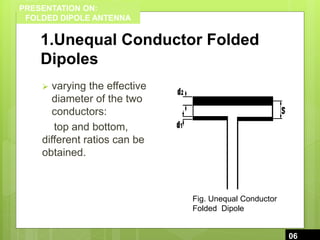
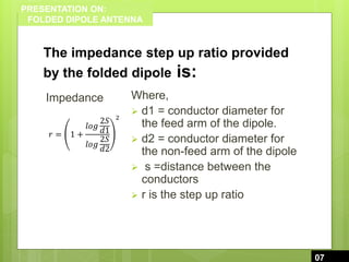
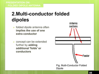
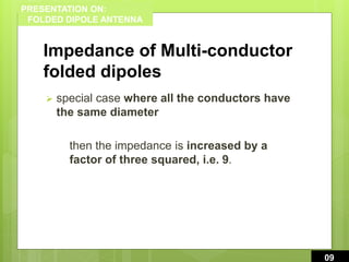
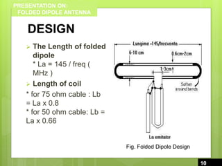


This document presents a comprehensive overview of folded dipole antennas, including their design, types, properties, and applications. It details the structure of these antennas, such as the relationship between conductor diameters and impedance, and emphasizes their advantages like increased impedance and wider bandwidth. Applications highlighted include their use in domestic television and VHF FM broadcast antennas.


![3_Antenna Array [Modlue 4] (1).pdf](https://cdn.slidesharecdn.com/ss_thumbnails/3antennaarraymodlue41-220419112111-thumbnail.jpg?width=640&height=640&fit=bounds)


