Download to read offline
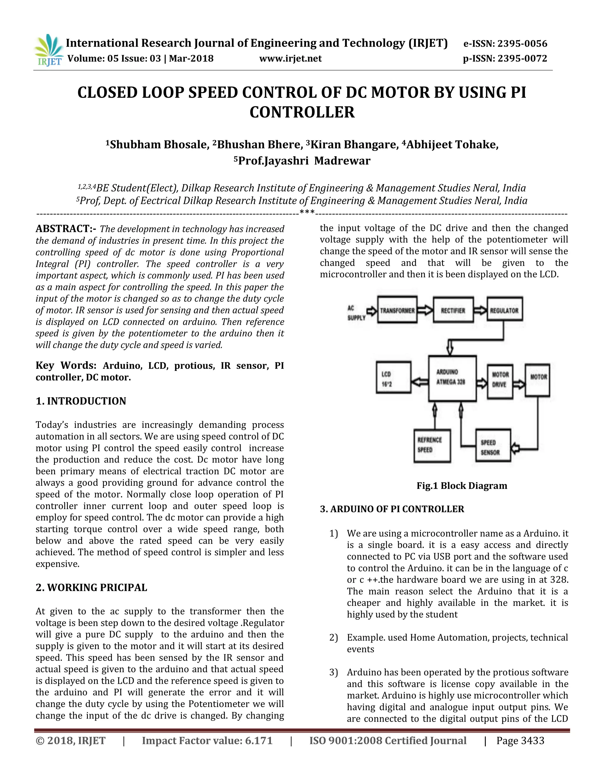
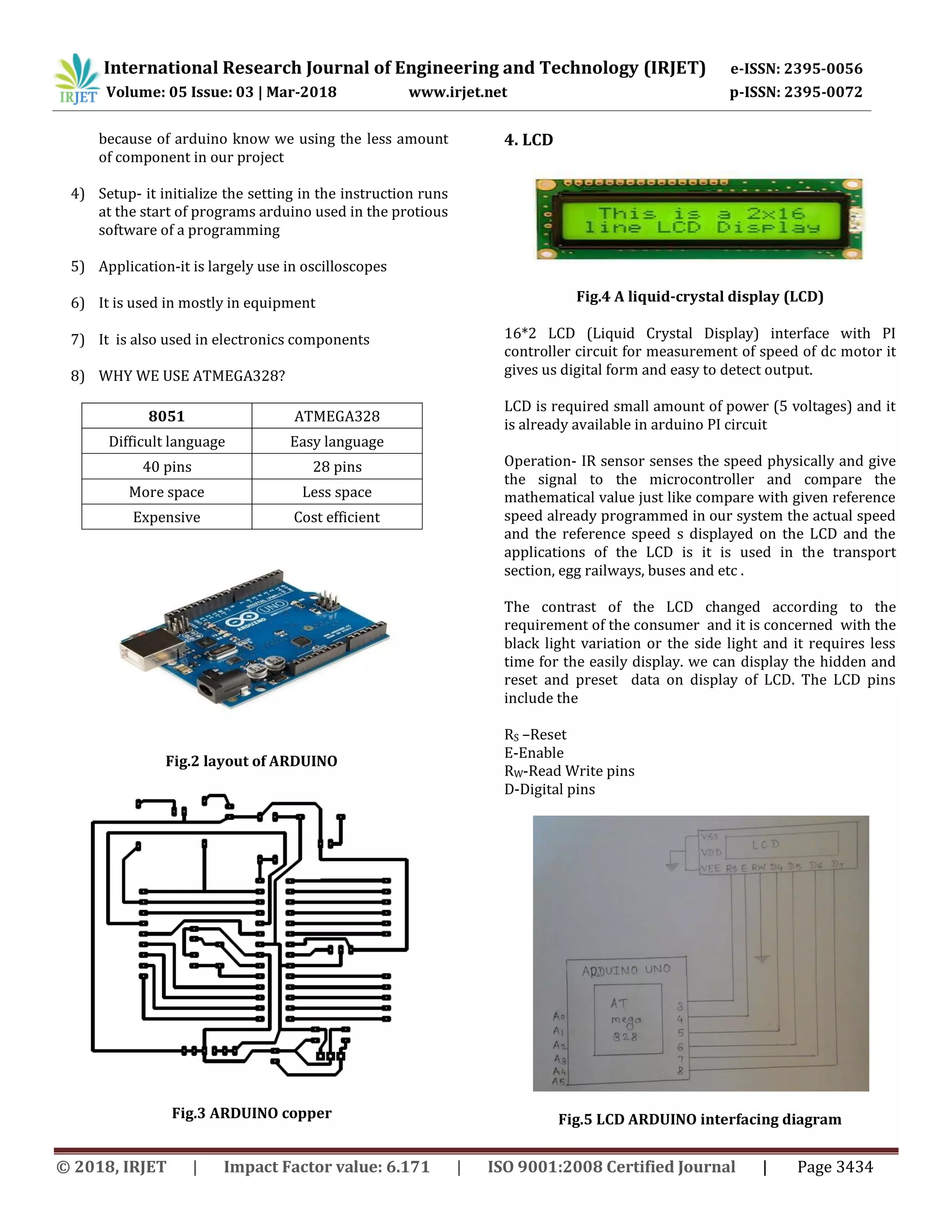


This document summarizes a research paper on closed loop speed control of a DC motor using a PI controller. It describes using an Arduino microcontroller to implement PI control and estimate the duty cycle to supply a DC motor driver to control motor speed. An IR sensor is used to sense actual motor speed, which is displayed on an LCD along with a reference speed input via a potentiometer. The PI controller generates an error signal to change the duty cycle and vary the motor speed accordingly. The system was able to rapidly track the desired reference speed, allowing closed loop speed control of the DC motor with low cost using an Arduino.