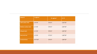
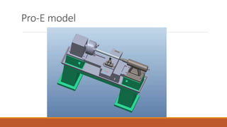
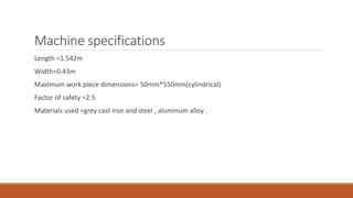
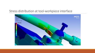
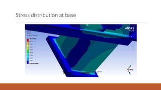
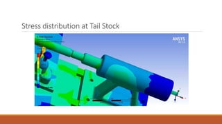
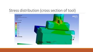
Machine tool(LATHE)
TALIYA HEMANTH
2012ABPS451H
MRUDUL NEKKANTI
2012ABPS525H
KONREDDY VARUN KUMAR REDDY
2012ABPS828H
SURYA TEJ BODDU
2012ABPS953H
MATERIAL SELECTION:
Any machine tool must be designed in such a way that it bears all the three important loads i.e,
Tension
Bending stress
Torsion
The weight of the bar is inversely proportional to the quantity E / ɤ , is known as unit stiffness of
the material in tension. The larger the unit stiffness of a material, the smaller is the weight of
the structure required to ensure the deflection of the structure due to a particular given load
does not exceed a specified value
Material E. kgf/cm2
ɤ.kgf/cm3 E / ɤ
LOW carbon steel 2.0*106 7.8*10-3 2.56*108
Medium carbon steel 2.1*106 7.8*10-3 2.69*108
Alloyed steel 2.1*106 7.8*10-3 2.69*108
Grey cast iron 1.2*106 7.2*10-3 1.66*108
Duraluminium 0.75*106 7.8*10-3 2.68*108
Property Steel Relation Cast iron
Strength steel > cast iron
Rigidity steel > cast iron
Wall thickness needed steel < cast iron
Casting steel < cast iron
Economy steel < cast iron
Part Material
Bed Grey cast iron
Head stock Steel
Tail stock Steel
Cross slide Steel
Carriage Grey cast iron
Tool post Steel
Pro-E model
Machine specifications
Length =1.542m
Width=0.43m
Maximum work piece dimensions= 50mm*550mm(cylindrical)
Factor of safety =2.5
Materials used =grey cast iron and steel , aluminum alloy .
Cutting forces
We basically look at turning operation on lathe machine and we tried to calculate the forces for
appropriate depth of cut and feed of the cutting tool.
Depth of cut=3mm
Feed =2mm/rev
Forces acting on the tool are
◦ Axial(Fa)
◦ Tangential(Ft)
◦ Radial(Fr)
Cutting forces calculation
Axial force= 2mm*3.14*50mm*1500
=805N
Calculated from the merchant circle diagram with a side rake angle of 8 and back rake angle of 6
degrees.
Radial force=315N
Tangential force=620N
Analysis
Static analysis of the structure is made on the ANSYS “static structural” module.
The governing constraint conditions are
The base is fixed i.e no degrees of freedom for it.
 The work piece is fixed onto the head stock and tail stocks rigidly.
 There is no sliding between the parts .
Meshed Assembly
Stress distribution at tool-workpiece interface
Stress distribution at base
Stress distribution at Tail Stock
Stress distribution (cross section of tool)
Conclusion
The lathe machine parts are assembled and are analysed for a real time machining operation
like turning and is tested for stress distribution , deformation, and torsion are calculated for each
part and the machine structure is allowable within the specified limits.

cutting forces(static) simulation on lathe

  • 1.
    Machine tool(LATHE) TALIYA HEMANTH 2012ABPS451H MRUDULNEKKANTI 2012ABPS525H KONREDDY VARUN KUMAR REDDY 2012ABPS828H SURYA TEJ BODDU 2012ABPS953H
  • 2.
    MATERIAL SELECTION: Any machinetool must be designed in such a way that it bears all the three important loads i.e, Tension Bending stress Torsion The weight of the bar is inversely proportional to the quantity E / ɤ , is known as unit stiffness of the material in tension. The larger the unit stiffness of a material, the smaller is the weight of the structure required to ensure the deflection of the structure due to a particular given load does not exceed a specified value
  • 3.
    Material E. kgf/cm2 ɤ.kgf/cm3E / ɤ LOW carbon steel 2.0*106 7.8*10-3 2.56*108 Medium carbon steel 2.1*106 7.8*10-3 2.69*108 Alloyed steel 2.1*106 7.8*10-3 2.69*108 Grey cast iron 1.2*106 7.2*10-3 1.66*108 Duraluminium 0.75*106 7.8*10-3 2.68*108
  • 4.
    Property Steel RelationCast iron Strength steel > cast iron Rigidity steel > cast iron Wall thickness needed steel < cast iron Casting steel < cast iron Economy steel < cast iron
  • 5.
    Part Material Bed Greycast iron Head stock Steel Tail stock Steel Cross slide Steel Carriage Grey cast iron Tool post Steel
  • 6.
  • 7.
    Machine specifications Length =1.542m Width=0.43m Maximumwork piece dimensions= 50mm*550mm(cylindrical) Factor of safety =2.5 Materials used =grey cast iron and steel , aluminum alloy .
  • 8.
    Cutting forces We basicallylook at turning operation on lathe machine and we tried to calculate the forces for appropriate depth of cut and feed of the cutting tool. Depth of cut=3mm Feed =2mm/rev Forces acting on the tool are ◦ Axial(Fa) ◦ Tangential(Ft) ◦ Radial(Fr)
  • 9.
    Cutting forces calculation Axialforce= 2mm*3.14*50mm*1500 =805N Calculated from the merchant circle diagram with a side rake angle of 8 and back rake angle of 6 degrees. Radial force=315N Tangential force=620N
  • 10.
    Analysis Static analysis ofthe structure is made on the ANSYS “static structural” module. The governing constraint conditions are The base is fixed i.e no degrees of freedom for it.  The work piece is fixed onto the head stock and tail stocks rigidly.  There is no sliding between the parts .
  • 11.
  • 12.
    Stress distribution attool-workpiece interface
  • 13.
  • 14.
  • 15.
  • 16.
    Conclusion The lathe machineparts are assembled and are analysed for a real time machining operation like turning and is tested for stress distribution , deformation, and torsion are calculated for each part and the machine structure is allowable within the specified limits.