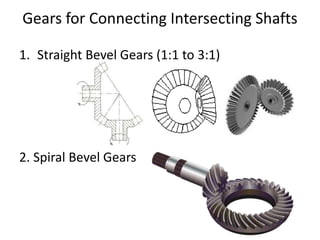
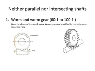
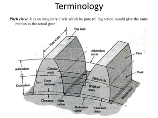
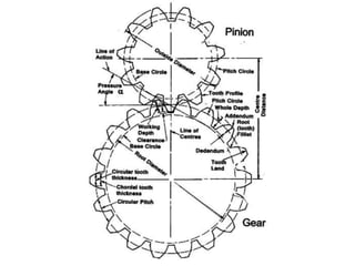
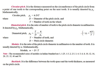
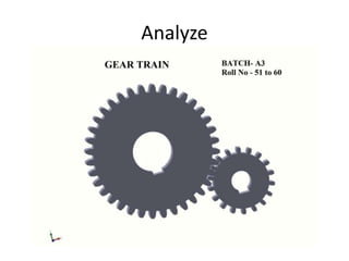
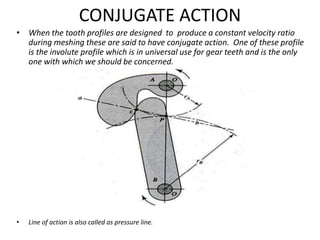
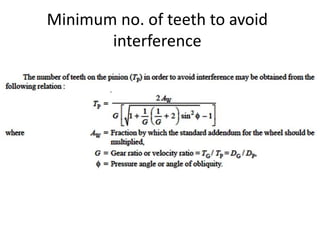
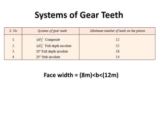
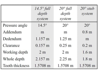
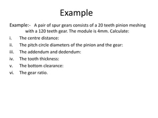
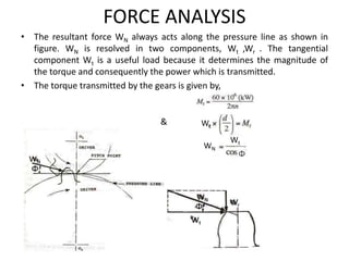
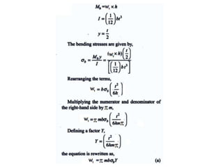
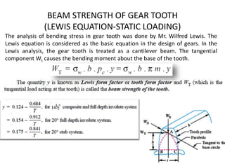
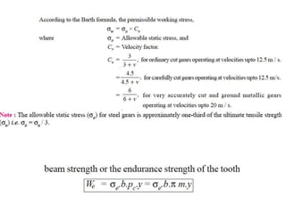
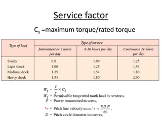
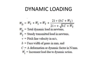
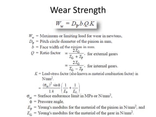
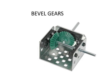
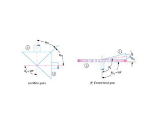
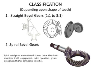
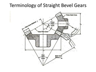
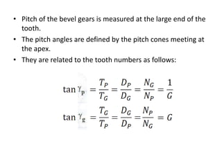
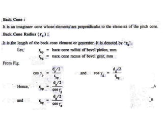
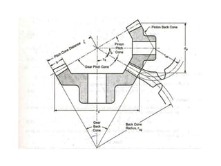
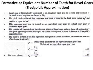
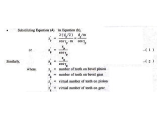
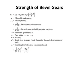
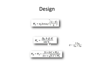
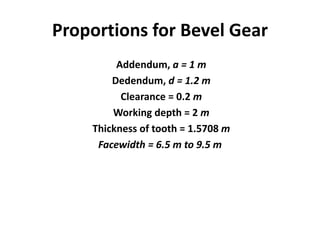
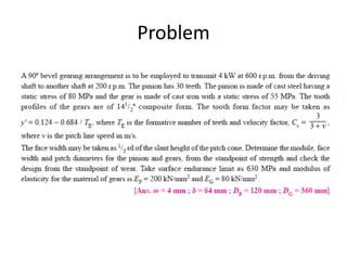
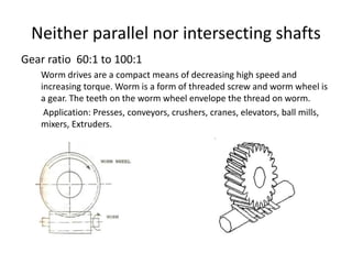
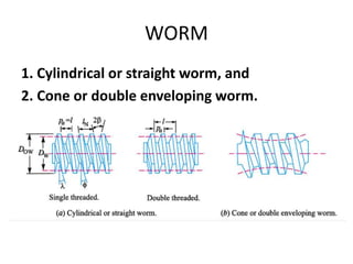
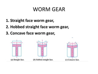
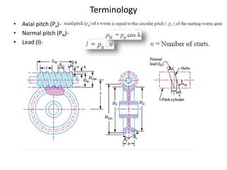
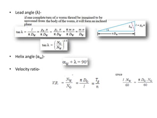
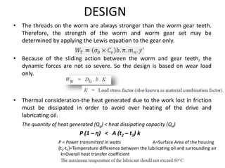
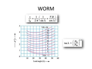
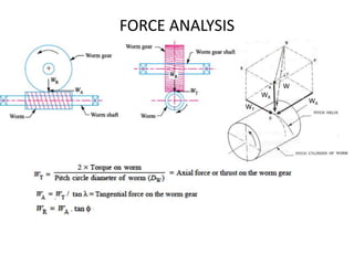
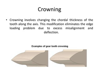
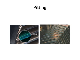
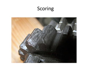
GEARS
Gears are defined as toothed wheels which transmit power and motion with
constant velocity ratio from one shaft to another by means of successive
engagement of teeth. Gear drives offer the following advantages compared
with chain or belt drives:
• It is a positive drive and the velocity ratio remains constant.
• The centre distance between the shafts is relatively small, which results in
compact construction.
• It can transmit very large power, which is beyond the range of belt or chain
drives.
• It can transmit motion at very low velocity, which is not possible with the belt
drives.
• The efficiency of gear drives is very high.
• A provision can be made in the gear box for gear shifting, thus changing the
velocity ratio over a wide range.
• But High cost and maintenance are considerations.
Introduction
CLASSIFICATION
Gears may be classified according to the relative position of the axes of
revolution.
• Parallel,
• Intersecting,
• Neither parallel nor intersecting
Gears for connecting parallel shafts
1. Spur Gears (6:1 to 10:1)
Teeth are parallel to the axis of the shaft.
Spur gear impose radial load on the shaft.
Noise in high speed application due to
sudden contact over the entire
facewidth.
2. Helical gears
Teeth are at an angle with the axis of the shaft.
Angle of helix is same for both gears
but the hand of helix is opposite.
Helical gear impose radial and thrust load
on the shaft.
Quiet operation in high speed power transmission
due to gradual contact. Costly in manufacturing.
APPLICATION- Automobiles, Turbines.
3. Herringbone Gears (or Double-helical Gears)
The construction result in equal and opposite thrust reaction balancing each other
Gears for Connecting Intersecting Shafts
1. Straight Bevel Gears (1:1 to 3:1)
2. Spiral Bevel Gears
Neither parallel nor intersecting shafts
1. Worm and worm gear (60:1 to 100:1 )
Worm is a form of threaded screw. Worm gears are specified by the high speed
reduction ratio
Terminology
Pitch circle. It is an imaginary circle which by pure rolling action, would give the same
motion as the actual gear
Analyze
Velocity Ratio, Transmission Ratio, Contact
Ratio & Gear Ratio
N2/N1 = D1/D2 = T1/ T2
Note: In quality gears contact ratio should be greater than one. As greater
contact ratio the noise level reduce due to low dynamic loading. Theoretical
explanation- there will more than one teeth in engagement at a time as the
diameter of one gear increases. Use imagination. It should be considered as an
alternative design solution for producing quieter gears without expensive
manufacturing processes or significant modifications to the gear unit structure,
especially in spur gear applications.
CONJUGATE ACTION
• When the tooth profiles are designed to produce a constant velocity ratio
during meshing these are said to have conjugate action. One of these profile
is the involute profile which is in universal use for gear teeth and is the only
one with which we should be concerned.
• Line of action is also called as pressure line.
Law of Gearing (Condition for
Constant Velocity Ratio )
• To transmit motion at a constant velocity ratio,
the pitch point must remain fixed; i.e. all the
lines of action for every instantaneous point of
contact must pass through the same point P.
Involute Profile
• The generating line de is normal to the involute at all points of
intersection and at the same time, is always tangent to the cylinder
A.
Pressure Angle
• The angle Ф is called the pressure angle. And is usually has the values of
200 and 14.50
• The circle tangent to pressure line are called the base circle.
Interference in Involute Gears
• A pinion gearing with a wheel is shown in Fig. A little consideration will show, that if the
radius of the addendum circle of pinion is increased, the tip of tooth on the pinion will
then undercut the tooth on the wheel at the root and remove part of the involute
profile of tooth on the wheel. This effect is known as interference and occurs when the
teeth are being cut. In brief, the phenomenon when the tip of a tooth undercuts the
root on its mating gear is known as interference.
• It can be reduced by increasing number of teeth on gear or by using stub teeth system
or by using a larger pressure angle.
Minimum no. of teeth to avoid
interference
Systems of Gear Teeth
Face width = (8m)<b<(12m)
Example
Example:- A pair of spur gears consists of a 20 teeth pinion meshing
with a 120 teeth gear. The module is 4mm. Calculate:
i. The centre distance:
ii. The pitch circle diameters of the pinion and the gear:
iii. The addendum and dedendum:
iv. The tooth thickness:
v. The bottom clearance:
vi. The gear ratio.
DESIGN OF SPUR GEARS
FORCE ANALYSIS
• The resultant force WN always acts along the pressure line as shown in
figure. WN is resolved in two components, Wt ,Wr . The tangential
component Wt is a useful load because it determines the magnitude of
the torque and consequently the power which is transmitted.
• The torque transmitted by the gears is given by,
& Wt
Wt
WN
BEAM STRENGTH OF GEAR TOOTH
(LEWIS EQUATION-STATIC LOADING)
The analysis of bending stress in gear tooth was done by Mr. Wilfred Lewis. The
Lewis equation is considered as the basic equation in the design of gears. In the
Lewis analysis, the gear tooth is treated as a cantilever beam. The tangential
component Wt causes the bending moment about the base of the tooth.
Service factor
Cs =maximum torque/rated torque
DYNAMIC LOADING
Wear Strength
DESIGN
• Find out, which one is weaker of the two wheels, pinion or gear. Following are the
guidelines for the same
This product is known as the strength factor.
• Apply the Lewis equation and find out the unknown (usually it is module).
Face width (b) may be taken as 8m to 12m.
• Check the design against dynamic load, wear load and interference.
For dynamic load – WD ≤ We
For wear load – WD ≤ Ww
For interference- Minimum no. of teeth of pinion to avoid interference ≤ Actual no. of teeth of pinion
• If the above design conditions are not satisfactory. Check the design for the next
standard value of module (from design data book).
• When the design becomes satisfactory, find other size parameters (addendum,
dedendum, clearance, face width, fillet radius, tooth thickness ) for the corresponding
module.
HELICAL GEARS
Helical gears
Teeth are at an angle with the axis of the shaft.
Angle of helix is same for both gears
but the hand of helix is opposite.
Helical gear impose radial and thrust load
on the shaft.
Quiet operation in high speed power transmission
due to gradual contact. Costly in manufacturing.
APPLICATION- Automobiles, Turbines.
Herringbone Gears (or Double-helical Gears)
The construction result in equal and opposite thrust reaction balancing each other
Terminology
For using the same system of teeth for
gear design as in case of Spur gear.
Systems of Gear Teeth
Face width = (8mn)<b<(12mn)
Where mn=m cosα
Force Analysis
DESIGN
nn
BEVEL GEARS
Introduction
• When gears are to be used to transmit motion
between intersecting shafts, bevel gear is
required. Although bevel gears are usually
made for a shaft angle of 90o, they may be
produced for almost any angle.
CLASSIFICATION
(Depending upon angles between the shafts)
1. Mitre gears. When equal bevel gears (having equal
teeth and equal pitch angles) connect two shafts whose
axes intersect at right angle, then they are known as
mitre gears.
2. Angular bevel gears. When the bevel gears connect
two shafts whose axes intersect at an angle other than
a right angle, then they are known as angular bevel
gears.
3. Crown bevel gears. When the bevel gears connect two
shafts whose axes intersect at an angle greater than a
right angle and one of the bevel gears has a pitch angle
of 90o, then it is known as a crown gear.
1. Straight Bevel Gears (1:1 to 3:1)
2. Spiral Bevel Gears
Spiral bevel gears are made with curved teeth. They have
smoother tooth engagement, quiet operation, greater
strength and higher permissible velocities.
CLASSIFICATION
(Depending upon shape of teeth)
Terminology of Straight Bevel Gears
L
• Pitch of the bevel gears is measured at the large end of the
tooth.
• The pitch angles are defined by the pitch cones meeting at
the apex.
• They are related to the tooth numbers as follows:
A
B
L
Formative or Equivalent Number of Teeth for Bevel Gears
(Tredgold’s Approximation)
A
Strength of Bevel Gears
Design
Proportions for Bevel Gear
Addendum, a = 1 m
Dedendum, d = 1.2 m
Clearance = 0.2 m
Working depth = 2 m
Thickness of tooth = 1.5708 m
Facewidth = 6.5 m to 9.5 m
Problem
Home assignment
• Forces Acting on a Bevel Gear
WORM GEARS
Neither parallel nor intersecting shafts
Gear ratio 60:1 to 100:1
Worm drives are a compact means of decreasing high speed and
increasing torque. Worm is a form of threaded screw and worm wheel is
a gear. The teeth on the worm wheel envelope the thread on worm.
Application: Presses, conveyors, crushers, cranes, elevators, ball mills,
mixers, Extruders.
Advantages-
a. High speed reduction.
b. Compact in construction
c. Operation is smooth and silent.
d. Self locking property for crane and other lifting devices.
Disadvantages-
a. Efficiency is low as compared with other types of gear drives.
b. The worm wheel is generally made of phosphor-bronze which
increases the cost.
c. Considerable amount of heat is generated in worm gear drives
which is required to be dissipated by a lubricating oil.
d. The power transmitting capacity is low as compared to the
other gear drives.
CLASSIFICATION OF WORM AND WORM GEAR
WORM
1. Cylindrical or straight worm, and
2. Cone or double enveloping worm.
WORM GEAR
1. Straight face worm gear,
2. Hobbed straight face worm gear,
3. Concave face worm gear,
Terminology
• Axial pitch (Pa)-
• Normal pitch (PN)-
• Lead (l)-
• Lead angle (λ)-
• Helix angle (αW)-
• Velocity ratio-
• since
Systems of Gear Teeth
FOR WORM
FOR GEAR
Efficiency
In data book divide the velocity by 60 or change the unit as m/min
DESIGNATION
A pair of worm gears is specified and designated by four quantities in the
following manner,
n/Tg/q/m
Where q is diametral quotient =
SELECTION OF MATERIALS
• The selection of the material for the worm and worm wheel is more
limited than other types of gears.
• Number of stress cycles on worm are very large than the worm gear.
Therefore the surface endurance strength should be more for the worm-
material. The core of the worm should be kept ductile to ensure maximum
energy absorption.
The worms are therefore made of case hardened steel.
• The worm wheel cannot be accurately generated in manufacturing. The
final profile and finish of the worm wheel teeth is the result of plastic
deformation during the initial stages of service. Therefore the worm wheel
material should be soft and conformable.
Phosphor-bronze with a surface hardness of 90-120 BHN, is used for the
wheel. Phosphor-bronze is costly so only the outer rim is made of
phosphor-bronze. It is then bolted to the cast iron wheel.
DESIGN
• The threads on the worm are always stronger than the worm gear teeth.
Therefore, the strength of the worm and worm gear set may be
determined by applying the Lewis equation to the gear only.
• Because of the sliding action between the worm and gear teeth, the
dynamic forces are not so severe. So the design is based on wear load
only.
• Thermal consideration-the heat generated due to the work lost in friction
must be dissipated in order to avoid over heating of the drive and
lubricating oil.
The quantity of heat generated (Qg) < heat dissipating capacity (Qd)
P (1 – η) < A (t2 – t1) k
P = Power transmitted in watts A=Surface Area of the housing
(t2-t1)=Temperature difference between the lubricating oil and surrounding air
k=Overall heat transfer coefficient
WORM
WR
WA
WT
W
FORCE ANALYSIS
HOME ASSIGNMENT
• ASSUMPTIONS
• FAILURE (Corrosion, Wearing, Pitting)
• MATERIAL SELECTION (CAST IRON, STEEL , BRONZE)
• MANUFACTURING METHODS (Milling, Forming, Hobbing,
Casting, Powder metallurgy)
• LUBRICATION (Grease, Mineral Oils- SAE 80, SAE90, SAE
140)
• COMPARISION BETWEEN CYCLOIDAL AND INVOLUTE TEETH
SYSTEM.
Crowning
• Crowning involves changing the chordal thickness of the
tooth along the axis. This modification eliminates the edge
loading problem due to excess misalignment and
deflection.
Pitting
Scoring
Gear design , classification  advantages and disadvantages

Gear design , classification advantages and disadvantages

  • 1.
  • 2.
    Gears are definedas toothed wheels which transmit power and motion with constant velocity ratio from one shaft to another by means of successive engagement of teeth. Gear drives offer the following advantages compared with chain or belt drives: • It is a positive drive and the velocity ratio remains constant. • The centre distance between the shafts is relatively small, which results in compact construction. • It can transmit very large power, which is beyond the range of belt or chain drives. • It can transmit motion at very low velocity, which is not possible with the belt drives. • The efficiency of gear drives is very high. • A provision can be made in the gear box for gear shifting, thus changing the velocity ratio over a wide range. • But High cost and maintenance are considerations. Introduction
  • 3.
    CLASSIFICATION Gears may beclassified according to the relative position of the axes of revolution. • Parallel, • Intersecting, • Neither parallel nor intersecting
  • 4.
    Gears for connectingparallel shafts 1. Spur Gears (6:1 to 10:1) Teeth are parallel to the axis of the shaft. Spur gear impose radial load on the shaft. Noise in high speed application due to sudden contact over the entire facewidth.
  • 5.
    2. Helical gears Teethare at an angle with the axis of the shaft. Angle of helix is same for both gears but the hand of helix is opposite. Helical gear impose radial and thrust load on the shaft. Quiet operation in high speed power transmission due to gradual contact. Costly in manufacturing. APPLICATION- Automobiles, Turbines. 3. Herringbone Gears (or Double-helical Gears) The construction result in equal and opposite thrust reaction balancing each other
  • 6.
    Gears for ConnectingIntersecting Shafts 1. Straight Bevel Gears (1:1 to 3:1) 2. Spiral Bevel Gears
  • 7.
    Neither parallel norintersecting shafts 1. Worm and worm gear (60:1 to 100:1 ) Worm is a form of threaded screw. Worm gears are specified by the high speed reduction ratio
  • 8.
    Terminology Pitch circle. Itis an imaginary circle which by pure rolling action, would give the same motion as the actual gear
  • 11.
  • 12.
    Velocity Ratio, TransmissionRatio, Contact Ratio & Gear Ratio N2/N1 = D1/D2 = T1/ T2 Note: In quality gears contact ratio should be greater than one. As greater contact ratio the noise level reduce due to low dynamic loading. Theoretical explanation- there will more than one teeth in engagement at a time as the diameter of one gear increases. Use imagination. It should be considered as an alternative design solution for producing quieter gears without expensive manufacturing processes or significant modifications to the gear unit structure, especially in spur gear applications.
  • 13.
    CONJUGATE ACTION • Whenthe tooth profiles are designed to produce a constant velocity ratio during meshing these are said to have conjugate action. One of these profile is the involute profile which is in universal use for gear teeth and is the only one with which we should be concerned. • Line of action is also called as pressure line.
  • 14.
    Law of Gearing(Condition for Constant Velocity Ratio ) • To transmit motion at a constant velocity ratio, the pitch point must remain fixed; i.e. all the lines of action for every instantaneous point of contact must pass through the same point P.
  • 15.
    Involute Profile • Thegenerating line de is normal to the involute at all points of intersection and at the same time, is always tangent to the cylinder A.
  • 16.
    Pressure Angle • Theangle Ф is called the pressure angle. And is usually has the values of 200 and 14.50 • The circle tangent to pressure line are called the base circle.
  • 17.
    Interference in InvoluteGears • A pinion gearing with a wheel is shown in Fig. A little consideration will show, that if the radius of the addendum circle of pinion is increased, the tip of tooth on the pinion will then undercut the tooth on the wheel at the root and remove part of the involute profile of tooth on the wheel. This effect is known as interference and occurs when the teeth are being cut. In brief, the phenomenon when the tip of a tooth undercuts the root on its mating gear is known as interference. • It can be reduced by increasing number of teeth on gear or by using stub teeth system or by using a larger pressure angle.
  • 18.
    Minimum no. ofteeth to avoid interference
  • 19.
    Systems of GearTeeth Face width = (8m)<b<(12m)
  • 21.
    Example Example:- A pairof spur gears consists of a 20 teeth pinion meshing with a 120 teeth gear. The module is 4mm. Calculate: i. The centre distance: ii. The pitch circle diameters of the pinion and the gear: iii. The addendum and dedendum: iv. The tooth thickness: v. The bottom clearance: vi. The gear ratio.
  • 22.
  • 23.
    FORCE ANALYSIS • Theresultant force WN always acts along the pressure line as shown in figure. WN is resolved in two components, Wt ,Wr . The tangential component Wt is a useful load because it determines the magnitude of the torque and consequently the power which is transmitted. • The torque transmitted by the gears is given by, & Wt Wt WN
  • 25.
    BEAM STRENGTH OFGEAR TOOTH (LEWIS EQUATION-STATIC LOADING) The analysis of bending stress in gear tooth was done by Mr. Wilfred Lewis. The Lewis equation is considered as the basic equation in the design of gears. In the Lewis analysis, the gear tooth is treated as a cantilever beam. The tangential component Wt causes the bending moment about the base of the tooth.
  • 27.
    Service factor Cs =maximumtorque/rated torque
  • 28.
  • 29.
  • 30.
    DESIGN • Find out,which one is weaker of the two wheels, pinion or gear. Following are the guidelines for the same This product is known as the strength factor. • Apply the Lewis equation and find out the unknown (usually it is module). Face width (b) may be taken as 8m to 12m. • Check the design against dynamic load, wear load and interference. For dynamic load – WD ≤ We For wear load – WD ≤ Ww For interference- Minimum no. of teeth of pinion to avoid interference ≤ Actual no. of teeth of pinion • If the above design conditions are not satisfactory. Check the design for the next standard value of module (from design data book). • When the design becomes satisfactory, find other size parameters (addendum, dedendum, clearance, face width, fillet radius, tooth thickness ) for the corresponding module.
  • 31.
  • 32.
    Helical gears Teeth areat an angle with the axis of the shaft. Angle of helix is same for both gears but the hand of helix is opposite. Helical gear impose radial and thrust load on the shaft. Quiet operation in high speed power transmission due to gradual contact. Costly in manufacturing. APPLICATION- Automobiles, Turbines. Herringbone Gears (or Double-helical Gears) The construction result in equal and opposite thrust reaction balancing each other
  • 33.
    Terminology For using thesame system of teeth for gear design as in case of Spur gear.
  • 35.
    Systems of GearTeeth Face width = (8mn)<b<(12mn) Where mn=m cosα
  • 36.
  • 37.
  • 38.
  • 40.
  • 41.
    Introduction • When gearsare to be used to transmit motion between intersecting shafts, bevel gear is required. Although bevel gears are usually made for a shaft angle of 90o, they may be produced for almost any angle.
  • 42.
    CLASSIFICATION (Depending upon anglesbetween the shafts) 1. Mitre gears. When equal bevel gears (having equal teeth and equal pitch angles) connect two shafts whose axes intersect at right angle, then they are known as mitre gears. 2. Angular bevel gears. When the bevel gears connect two shafts whose axes intersect at an angle other than a right angle, then they are known as angular bevel gears. 3. Crown bevel gears. When the bevel gears connect two shafts whose axes intersect at an angle greater than a right angle and one of the bevel gears has a pitch angle of 90o, then it is known as a crown gear.
  • 44.
    1. Straight BevelGears (1:1 to 3:1) 2. Spiral Bevel Gears Spiral bevel gears are made with curved teeth. They have smoother tooth engagement, quiet operation, greater strength and higher permissible velocities. CLASSIFICATION (Depending upon shape of teeth)
  • 45.
  • 46.
    • Pitch ofthe bevel gears is measured at the large end of the tooth. • The pitch angles are defined by the pitch cones meeting at the apex. • They are related to the tooth numbers as follows:
  • 47.
  • 48.
  • 49.
    Formative or EquivalentNumber of Teeth for Bevel Gears (Tredgold’s Approximation)
  • 50.
  • 51.
  • 52.
  • 53.
    Proportions for BevelGear Addendum, a = 1 m Dedendum, d = 1.2 m Clearance = 0.2 m Working depth = 2 m Thickness of tooth = 1.5708 m Facewidth = 6.5 m to 9.5 m
  • 54.
  • 55.
    Home assignment • ForcesActing on a Bevel Gear
  • 56.
  • 57.
    Neither parallel norintersecting shafts Gear ratio 60:1 to 100:1 Worm drives are a compact means of decreasing high speed and increasing torque. Worm is a form of threaded screw and worm wheel is a gear. The teeth on the worm wheel envelope the thread on worm. Application: Presses, conveyors, crushers, cranes, elevators, ball mills, mixers, Extruders.
  • 58.
    Advantages- a. High speedreduction. b. Compact in construction c. Operation is smooth and silent. d. Self locking property for crane and other lifting devices. Disadvantages- a. Efficiency is low as compared with other types of gear drives. b. The worm wheel is generally made of phosphor-bronze which increases the cost. c. Considerable amount of heat is generated in worm gear drives which is required to be dissipated by a lubricating oil. d. The power transmitting capacity is low as compared to the other gear drives.
  • 59.
  • 60.
    WORM 1. Cylindrical orstraight worm, and 2. Cone or double enveloping worm.
  • 61.
    WORM GEAR 1. Straightface worm gear, 2. Hobbed straight face worm gear, 3. Concave face worm gear,
  • 62.
    Terminology • Axial pitch(Pa)- • Normal pitch (PN)- • Lead (l)-
  • 63.
    • Lead angle(λ)- • Helix angle (αW)- • Velocity ratio- • since
  • 64.
    Systems of GearTeeth FOR WORM FOR GEAR
  • 65.
    Efficiency In data bookdivide the velocity by 60 or change the unit as m/min
  • 66.
    DESIGNATION A pair ofworm gears is specified and designated by four quantities in the following manner, n/Tg/q/m Where q is diametral quotient =
  • 67.
    SELECTION OF MATERIALS •The selection of the material for the worm and worm wheel is more limited than other types of gears. • Number of stress cycles on worm are very large than the worm gear. Therefore the surface endurance strength should be more for the worm- material. The core of the worm should be kept ductile to ensure maximum energy absorption. The worms are therefore made of case hardened steel. • The worm wheel cannot be accurately generated in manufacturing. The final profile and finish of the worm wheel teeth is the result of plastic deformation during the initial stages of service. Therefore the worm wheel material should be soft and conformable. Phosphor-bronze with a surface hardness of 90-120 BHN, is used for the wheel. Phosphor-bronze is costly so only the outer rim is made of phosphor-bronze. It is then bolted to the cast iron wheel.
  • 68.
    DESIGN • The threadson the worm are always stronger than the worm gear teeth. Therefore, the strength of the worm and worm gear set may be determined by applying the Lewis equation to the gear only. • Because of the sliding action between the worm and gear teeth, the dynamic forces are not so severe. So the design is based on wear load only. • Thermal consideration-the heat generated due to the work lost in friction must be dissipated in order to avoid over heating of the drive and lubricating oil. The quantity of heat generated (Qg) < heat dissipating capacity (Qd) P (1 – η) < A (t2 – t1) k P = Power transmitted in watts A=Surface Area of the housing (t2-t1)=Temperature difference between the lubricating oil and surrounding air k=Overall heat transfer coefficient
  • 69.
  • 70.
  • 71.
    HOME ASSIGNMENT • ASSUMPTIONS •FAILURE (Corrosion, Wearing, Pitting) • MATERIAL SELECTION (CAST IRON, STEEL , BRONZE) • MANUFACTURING METHODS (Milling, Forming, Hobbing, Casting, Powder metallurgy) • LUBRICATION (Grease, Mineral Oils- SAE 80, SAE90, SAE 140) • COMPARISION BETWEEN CYCLOIDAL AND INVOLUTE TEETH SYSTEM.
  • 72.
    Crowning • Crowning involveschanging the chordal thickness of the tooth along the axis. This modification eliminates the edge loading problem due to excess misalignment and deflection.
  • 73.
  • 74.