Project documents on weight optimization of lathe bed
•Download as DOCX, PDF•
1 like•1,620 views

we have to select the various material of lathe and remove it and use different material apart from it in order to get better property of lathe bed and reduce the cost.

Recommended
Recommended
More Related Content
What's hot
What's hot (20)
Similar to Project documents on weight optimization of lathe bed
Similar to Project documents on weight optimization of lathe bed (20)
More from College
More from College (15)
Recently uploaded
Recently uploaded (20)
Project documents on weight optimization of lathe bed
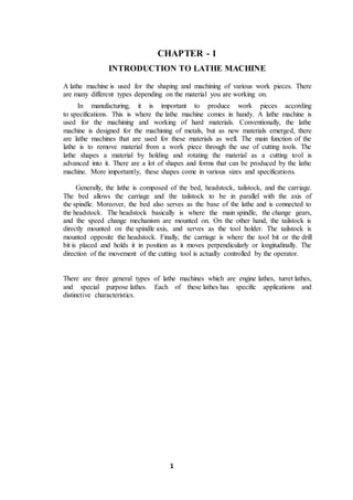
- 1. 1 CHAPTER - 1 INTRODUCTION TO LATHE MACHINE A lathe machine is used for the shaping and machining of various work pieces. There are many different types depending on the material you are working on. In manufacturing, it is important to produce work pieces according to specifications. This is where the lathe machine comes in handy. A lathe machine is used for the machining and working of hard materials. Conventionally, the lathe machine is designed for the machining of metals, but as new materials emerged, there are lathe machines that are used for these materials as well. The main function of the lathe is to remove material from a work piece through the use of cutting tools. The lathe shapes a material by holding and rotating the material as a cutting tool is advanced into it. There are a lot of shapes and forms that can be produced by the lathe machine. More importantly, these shapes come in various sizes and specifications. Generally, the lathe is composed of the bed, headstock, tailstock, and the carriage. The bed allows the carriage and the tailstock to be in parallel with the axis of the spindle. Moreover, the bed also serves as the base of the lathe and is connected to the headstock. The headstock basically is where the main spindle, the change gears, and the speed change mechanism are mounted on. On the other hand, the tailstock is directly mounted on the spindle axis, and serves as the tool holder. The tailstock is mounted opposite the headstock. Finally, the carriage is where the tool bit or the drill bit is placed and holds it in position as it moves perpendicularly or longitudinally. The direction of the movement of the cutting tool is actually controlled by the operator. There are three general types of lathe machines which are engine lathes, turret lathes, and special purpose lathes. Each of these lathes has specific applications and distinctive characteristics.
- 2. 2 1.1 MAIN PARTS OF THE LATHE MACHINE Fig.1 Main parts of the lathe machine The bed of Lathe acts as the base on which the different fixed and operations parts of the Lathe are mounted. Lathe beds are usually made as single piece casting of semi-steel (i.e., toughened cast iron), with the addition of small quantity of steel scrap to the cast iron during melting; the material ‘cast iron’ facilitating an easy sliding action. In case of extremely large machines, the bed may be in two or more pieces, bolted together to from the desired length. Lathe Bed are heavy rigid structure which is having high damping capacity for the vibrations generated by machines during machining. The rigid structure will helps to avoid deflections. The guides and ways which are present on the top of the bed will act as rails and supports other parts like tail stock. The bed will be designed in such a way that easily bolted to the floor of the machine shop. 1.1.1 Head stock: The head stock is the part of the lathe which serves as a housing for the driving pulleys and back gears, provides bearing for the machine spindle and keeps the latter in alignment with the bed. It is a fixed part which will present on the left side of the lathe bed. Head stock will consists of a hollow spindle and drives unit like main spindle, feed reverse lever, live center cone pulley etc., The tapered bar with pointed or projected end is going to grip the work piece between two centers of lathe bed. 1.1.2 Tail stock: It is also sometimes called the LOOSE HEAD- STOCK or PUPPET HEAD. It is mounted on the bed of the lathe such that it is capable of sliding along the latter maintaining its alignment with the head stock. On common types of medium size or small size lathes it is moved along the bed by hand, whereas in heavier types of lathes
- 3. 3 it is moved by means of a hand wheel through a pinion which meshes with the rack provided on the front of the lathe bed. The main function of the Tail stock is to provide bearing and support to the job which is being worked between centers. To enable this, the tail stock is made to possess a number of parts which collectively help in its successful function. 1.1.3 Carriage: The lathe carriage serves the purpose of supporting, guiding and feeding the tool against the job during the operation of the lathe. The carriage will present between head stock and tail stock which will slides on the bed ways of the lathe bed. The carriage will give feed to the tool and it holds the tool, for taper turning the feed is cross feed, for turning it is longitudinal feed. The carriage consists of the following parts. 1. saddle 2. cross-slide 3. compound Rest 4. Tool post 5. Apron 1.1.3.1 Saddle: It is the part of the carriage which slides along the bed way and support the Cross- slide, compound rest and Tool post. 1.1.3.2 Cross-slide: The cross-slide function is to provide cutting action to the tool and the action of cutting tool will be perpendicular to center line of lathe. It can either be operated by hand, by means of the cross-feed screw, or may be given power feed through the Apron Mechanism. 1.1.3.3 Compound Rest: The compound Rest will be placed over the cross slide and it consists of a graduated circular base which is having swivelling nature. 1.1.3.4 Tool post: It is the top most part of the carriage and is used for holding the tool or tool holder in position. 1.1.3.5 Apron: Apron houses the feed mechanism, clutch mechanism split half nut, gears, leavers, the apron wheel can be rotated by hand for longitudinal motion of the carriage. 1.1.4 Legs: They are the supports which carry the entire load of the machine over them. The prevailing practice is to use cast legs. Both the legs are firmly secured to the floor by means of foundation blots in order to prevent vibrations in the machine. One of these
- 4. 4 legs, usually the one on the left hand side of the operator, serves as a housing for the electric motor and countershaft etc., both these legs should be of robust construction. 1.2 TYPES OF LATHE MACHINES 1.2.1 Engine lathes: These are probably the most popular among the lathe machines. In fact, no machine shop is seen without this type of lathe. The good thing about engine lathes is that it can be used in various materials, aside from metal. Moreover, the set-up of these machines is so simple that they are easier to use. Its main components include the bed, headstock, and tailstock. These engine lathes can be adjusted to variable speeds for the accommodation of a wide scope of work. In addition, these lathes come in various sizes. 1.2.2 Turret Lathes: These types of lathes are used for machining single work pieces sequentially. This means that several operations are needed to be performed on a single work piece. With the turret lathes, sequential operations can be done on the work piece, eliminating errors in work alignment. With this set-up, machining is done more efficiently. Correspondingly, time is saved because there is no need to remove and transfer the work piece to another machine anymore. 1.2.3 Special Purpose Lathes: As the name implies, these lathes are used for special purposes such as heavy- duty production of identical parts. In addition, these lathes also perform specific functions that cannot be performed by the standard lathes. Some examples of special purpose lathes include the bench-type jewellers’ lathes, automatic lathes, crankshaft lathes, duplicating lathes, multi spindle lathes, brake drum lathes, and production lathes among others.
- 5. 5 CHAPTER – 2 LITERATURE SURVEY 2.1. DESIGN AND STRUCTURAL ANALYSIS OF CNC VERTICALMILLING MACHINE BED B. Malleswara Swami1, K.Sunil Ratna Kumar2 Address for Correspondence 1 PG Student, 2Assistant Professor Department of Mechanical Engineering, SIR C.R.R. College of Engineering(Affiliated to Andhra University) Eluru-534007, West Godavari Dist, A.P ABSTRACT: In this paper, a machine bed (Manufacturer: M/s Lokesh Machine Tools Ltd) is selected for the complete analysis for both static and dynamic loads. Then investigation is carried out to reduce the weight of the machine bed without deteriorating its structural rigidity and the accuracy of the machine tool by adding ribs at the suitable locations. In this work, the 3D CAD model for the base line and the optimized design has been created by using commercial 3D modeling software CATIA. The 3D FE model has been generated using HYPERMESH. The analyses were carried out using ANSYS and Design Optimization is done with the help of Optistruct. The results were shown with the help of graphs to analyze the effect of Weight reduction on the structural integrity of the machine bed before and after the weight reduction and conclusions were drawn about the optimized design. CONCLUSION: The following points are concluded on a milling machine bed • From the above results, the weight optimization of milling machine bed structure has been decrease by 16.1 Kg from 1056.31Kg to 1040.2 Kg (approximately 1.5%), hence the manufacturing cost also has been reduced. • From the above results, the G15 was selected as the best material due to low stresses and high natural frequencies, when it is compared with other materials. • The von-mises stress for G15 was increased from 26.1305 to 33.2082 N/mm2 in structural analysis. (Approximately 21.31%). • The natural frequency is also incresed.200 Hz to 215 Hz (approximately 6.9%). • The Effect of Von-mesis stress for G15 was increased and it is in permissible safe limit. • Structural ribs with hollow offers a method to improve the conventional design of machine structure. Based on structural modifications, ribs parameters and distributions can be further optimized.
- 6. 6 2.2. Designof Milling Machine Frame and Lathe Bed by Using MATLAB N. Lenin Rakesh, V. Palanisamy and G. Ravikanth Department of Mechanical Engineering, Bharath Institute of Science and Technology P.O. Box: 600073 Chennai, India ABSTRACT: This project deals with the design and analysis of lathe bed and milling machine frame by using MATLAB programming. Initially the design and analysis are done analytically and later verified by MATLAB programming using the required parameters. CONCLUSION: The complete design procedure of both the Lathe bed and Milling machine frame has been studied carefully and the program has been written using the MATLAB programming software. The manual calculation of each design has been verified using MATLAB results. The manual results and the MATLAB results are given below. Lathe Bed: Manual Result for stress : 0.0026 N/mm . MATLAB Result for stress : 0.0029 N/mm . Milling Machine Frame Manual Result for Deflection : 748mm. MATLAB Result for Deflection : 750mm. 2.3. Static and Dynamic Analysis of Base of Vertical Machining Center Nikunj Aadeshra, Prof. R. L. Patel 1 PG Student, Mechanical Engg.Deptt, C.U.Shah University, Wadhwan city, Gujarat. 2 Asst. Professor, Mechanical Engg.Deptt, C.U.Shah University, Wadhwan city. ABSTRACT: In industry the machine tool aims for high precision and repeatability while it is in operation. Generally machine tool contain several Structural components like base, saddle, headstock ,column of the machine tool play a vital role in helping to achieve consistent performance. Vertical machining center base selected for present study because base is the main structural part of the machine tool. It is a force bearing component of machine tool so it must contain high structural stiffness and good damping characteristics during machining operations. Otherwise it will affect accuracy and performance of that machine tool. So that to overcome this type of issue it is must need to analyze the structure. It is very difficult to analyse the structure analytically and the accurate results for stress, deflection etc. are the limitation of this method in Machine tool. So FEA is the best way to analyze the structural part of the machine tool. Static analysis is useful for estimating stresses, strains and deflections, whereasdynamic analysis deals with the prediction of natural frequencies and
- 7. 7 corresponding mode shapes, which will in turn, prevent the catastrophic failure of the machine tool. CONCLUSION: From the literature review, we can conclude that analysis of the machine tool structure for the various purpose by the analytical method is the more time consuming and very complex method also it doesn’t gives the precise way for the analysis because of its complexity but by using the FEA software we can get batter result with the more precision and more accurately than analytic method and also in this FEA , Static and Dynamic analysis of machine tool structures plays an important role on the efficiency and job accuracy of the machine tool. Static analysis is useful for estimating stresses, strains and deflections, and also improving structural stiffness where as dynamic analysis deals with the prediction of natural frequencies and corresponding mode shapes, which will in turn; prevent the catastrophic failure of the machine tool structures. 2.4. DESIGN AND ANALYSIS OF A MACHINE TOOLSTRUCTURE BASED ON STRUCTURAL BIONICS Sujeet Ganesh Kore1*, M I Sakri2 and L N Karadi3 *Corresponding Author: Sujeet Ganesh Kore,sujeetkore@gmail.com ABSTRACT: A structural bionic design process is systematically presented for lightweight mechanical structures. By mimicking biological excellent structural principles, the structure of lathe bed or the stiffening ribs of a lathe bed were redesigned for better load-bearing efficiency. In this paper, a machine bed (Manufacturer: Indira Machine Tools Ltd.) is selected for the complete analysis for static loads. Then investigation is carried out to reduce the weight of the machine bed, reduce the stress induced in the lathe bed and to reduce the displacement. In this work, the 3D CAD model for the existing bed model and the optimized bed model has been created by using commercial 3D modeling software SOLID EDGE V20. The analyses were carried out using ANSYS 13. The results were discussed. CONCLUSION: From the above results, the weight optimization of lathe machine bed has been achieved (Approximately 15%) for all the three material, hence the manufacturing cost also has been reduced. • The von-mises stress for Optimized model 2 and Optimized model 3 has been reduced. (Approximately 19%).The Natural frequency is also Improved (i.e., increased) for Optimized models. • From the above results, Optimized model 2 selected as the best model due to low stresses, low weight, less displacements and high natural frequencies, when it is compared with original model.
- 8. 8 2.5. Modeling and Analysis of CNC Milling Machine Bed with Composite Material Venkata Ajay Kumar. G1 V. Venkatesh2 1,2Assistant Professor 1Department of Mechanical Engineering 1,2Annamacharya Institute of Technology & Sciences, Rajampeta. ABSTRACT: Structural materials used in a machine tool have a decisive role in determining the productivity and accuracy of the part manufactured in it. The conventional structural materials used in precision machine tools such as cast iron and steel at high operating speeds develop positional errors due to the vibrations transferred into the structure. Faster cutting speeds can be acquired only by structure which has high stiffness and good damping characteristics. Clearly the life of a machine is inversely proportional to the levels of vibration that the machine is subjected. The further process is carried out to undergo the deformation, natural frequency and displacement using Static analysis, Modal analysis and Harmonic analysis respectively. Since the bed in machine tool plays a critical role in ensuring the precision and accuracy in components. It is one of the most important tool structures which tend to absorb the vibrations resulting from the cutting operation. To analyze the bed for possible material changes that could increase stiffness, reduce weight, improve damping characteristics and isolate natural frequency from the operating range. This was the main motivation behind the idea to go in for a composite model involving High Modulus Carbon Fiber Reinforced Polymer Composite Material (HM CFRP). Though carbon has good strength and stiffness properties but it lacks in damping requirements. On the other hand polymer, though it lacks in strength but it has good damping characteristics and it is used to hold the carbon fibers. This makes it ideal to combine these materials in a proper manner. In this work, a machine bed is selected for the analysis static loads. Then investigation is carried out to reduce the weight of the machine bed without deteriorating its structural rigidity. The 3D CAD model of the bed has been created by using commercial 3D modeling software and analyses were carried out using ANSYS. CONCLUSION: Based on the configuration principles, the existing bed material was replaced by HM CFRP material shows improve in the static characteristics. Simulations results show that the static characteristics of the machine bed have been improved. Generally Composite materials also offer high specific strength and high specific modulus with less weight in machine tool industries. This composite materials offers high accuracy and precession of the component manufactured in such machine tools made of composite materials. By considering all the results, the induced deformation and strain in HM CFRP machine bed is less than conventional cast iron machine beds because specific strength and specific rigidity of HMCFRP machine bed is more than cast iron. The work suggests that HM CFRP material is best suited for CNC milling machine bed.
- 9. 9 CHAPTER– 3 INTRODUCTION TO FEM 3.1. FEM - HISTORICAL BACKGROUND: The ideas of FEM (Finite Element Method) was evolved gradually from the significant contributions of many people from different fields of engineering (applied mathematics, and physics).The basic idea of FEM originated from advances in aircraft structural analysis. Mathematician named Courant proposed the theoretical basis of FEM in early 1940 1941: Hrenikoff found out that the elastic behavior of a physically continuous plate would be similar, under certain loading conditions, to framework of physically separate one dimensional rods and beams, connected together as discrete points. The problem then handles for trusses and frameworks with similar computational methods. 1943: Courant put the first efforts to use piecewise continuous function defined over triangular domains. He used an assemblage of triangular elements and principle of minimum potential energy to study the St.Venant torsion problem 1946: Schoenberg gave birth to the theory of splines, recommending the use of piecewise polynomials for approximation and interpolation. 1956: In 1956 the actual solution of plane stress problems by means of triangular elements whose properties were determined from the equations of elasticity theory was first given by Turner, Clough, Martin and Topp. These investigators were the first to introduce direct stiffness method for determining finite elements properties. 1957:Linear functions were defined over triangular elements with Reitz procedure developed by Synge. 1959: In 1959 Greenstadt brought out a new approach by involving a new term called “CELLS”. He imagined the solution domain is divided into set of contiguous sub domains in the form of “Cells”. In his approach he represents an “unknown function” by the series of functions, which is associated with each cell. His theory consists of irregular shaped cell meshes and it contains many of essential and fundamental ideas that serve as the mathematical basis for the FEM (Finite Element Method). In middle year’s scientist were involved in development of software to analysis frameworks, and to solve the 3-D problems using tetrahedral elements. Turner in 1956 modeled the add-shaped wings panels of high speed aircraft as an assemblage of smaller panels of simple triangular shape. This was a breakthrough as it made it possible to model two- or- three dimensional pieces. In earlier days FEA (Finite Element Analysis) was limited to expensive mainframe computers generally owned by aeronautics, automotive, defense and nuclear industries. With rapid growth in technology Finite Element Analysis has been developed to an incredible precision.
- 10. 10 3.2. Finite Element Methods (FEM): The Finite Element Method (FEM) is a numerical analysis technique used by the engineers, scientists, and mathematicians to obtain solutions to the differential equations that describe, or approximately describe a wide variety of physical and non-physical problems. Physical problems range in diversity from solid, fluid and soil mechanics, to electromagnetism or dynamics. 3.2.1. Applications of FEM: The finite element methods are mostly used in the field of structural mechanics. It is also used for solving problems on “Heat Transfer”, “Fluid Dynamics”, “Deformation and stress analysis of automobile and aircraft”, “electric and magnetic fields”. FEM is also applied on the following fields Civil engineering: Analysis of trusses, frames, folded plates, shell, roofs, bridges, and pre-stressed concrete structure, shear walls. Aircraft structures: Analysis of aircraft wings, fin, rockets, spacecraft and missile structures. Mechanical Design: Stress analysis of pressure vessel, piston, composite materials, linkages and gears. Heat Conduction: Temperature distribution in solids and fluids. Hydraulics and water resources engineering: Analysis of potential flows, free surface flows, and hydraulic structural and dams. Electrical machines and electromagnetic: Analysis of synchronous and induction machines, eddy current and the core losses in electric machine. The following software packages are commonly used for finite element analysis 1) Nastran 2) ANSYS and 3) Abaqus 3.2.2. Advantages and Disadvantages of FEA: Advantages: Complex irregular models can be solved. Any general load condition can be handled without difficulty Boundary conditions can be handled easily. Size of the element can varied to get accurate results Finite element analysis are easy and involves less cost Finite Element Analysis can save huge amount of design time. Finite Element Analysis can handle non-linear behaviour existing with large deformation and non-linear materials. Disadvantages: Finite element analysis is a time consuming process, it requires longer time for solving. FEA provides approximate solution. Huge computing facility is required for solving complex problems. Finite Element analysis of any problem requires better understanding of Mathematics, especially matrix, algebra, differentiation and integration.
- 11. 11 The result of FEM is closer when it has maximum number of smallelements. 3.3. METHODS OF ENGINEERING ANALYSIS There are basically three methods for analyzing engineering problems. They are: 1) Experimental methods 2) Analytical methods 3) Numerical methods. 3.3.1. Experimental methods: In this method, the actual product itself is tested as a prototype, to know the strength of the product. The prototype is subjected to continuous forces till it breaks. By this way, the strength of the product will be analyzed. Since this process requires large amount of material wastage, this method is followed only if in cases where other analyzing methods cannot be used. 3.3.2. Analytical methods: Analytical solution is a classical approach that is taught normally in engineering courses. Only simple and regular shaped problems such as, cantilever, shafts, plates, cylinders, simple supported beams etc can be analyzed by this method. Real life problems are quite complex and complicated that it cannot be solved using analytical approach. 3.3.3. Numerical methods: Numerical solutions are the mathematical representation of an actual problem. Any problem can be represented by three basic elements “spring”, “mass” and “damper”. All real life complicated problems can be solvedusing numerical methods. But this method involves lots of assumptions. Hence the result of numerical method solution will be approximate. Four major methods considered as numerical solution method are: 3.3.3.1 Finite Element Method -- FEM 3.3.3.2 Boundary Element Method -- BEM 3.3.3.3 Finite Volume Method -- FVM 3.3.3.4 Finite Difference Method -- FDM 3.3.3.1 Finite Element Method (FEM): The finite element method is a numerical analysis technique used by engineers, scientists, and mathematicians to obtain solutions to the differential equations that describe, or approximately describe a wide variety of physical (and non-physical) problems. Physical problems range in diversity from solid, fluid and soil mechanics, to electromagnetism or dynamic 3.3.3.2 Boundary Element Method (BEM): The boundary element method (BEM) is a numerical computational method of solving linear partial differential equations which have been formulated as integral equations (i.e. in boundary integral form). It can be applied in many areas of
- 12. 12 engineering and science including fluid mechanics, acoustics, electromagnetic, and fracture mechanics. (In electromagnetic, the more traditional term "method of moments" is often, though not always, synonymous with "boundary element method". 3.3.3.3 Finite Volume Method (FVM): The finite-volume method is a method for representing and evaluating partial differential equations in the form of algebraic equations]. Similar to the finite difference method or finite element method, values are calculated at discrete places on a meshed geometry. "Finite volume" refers to the small volume surrounding each node point on a mesh. In the finite volume method, volume integrals in a partial differential equation that contain a divergence term are converted to surface integrals, using the divergence theorem. These terms are then evaluated as fluxes at the surfaces of each finite volume. Because the flux entering a given volume is identical to that leaving the adjacent volume, these methods are conservative. Another advantage of the finite volume method is that it is easily formulated to allow for unstructured meshes. The method is used in many computational fluid dynamics packages. 3.3.3.4 Finite Difference Method (FDM): This is widely applicable Discretization method for the solution of ordinary and partial differential equations. In this approach all derivatives are replaced by approximations that involve solution values only, so in general the differential equations is reduced to a system of non-linear equations or linear algebraic equations. 3.4 IMPORTANT STEPS IN FEM ANALYSIS 3.4.1 Discretisation of the structure: The first step in the finite element analysis is to divide the continuous complex structure into discrete entities called finite elements. Smaller the element size, more accurate the results but larger the computation time. Coarser the elements, lesser computational time, and lesser accuracy of results. Therefore element size has to be judiciously chosen based on the application. Fig shows the various elements used for finite element analysis.
- 13. 13 Fig.2 Various elements used in FEM 3.4.2. Selection of the shape functions: This step involves choosing a displacement shape function within each element. The function is defined within the element using nodal values of the elements. “Linear, quadratic and cubic polynomials” are frequently used functions because they are simple to work with finite element formulation. Higher the degree of shape function, more accurate is the result. Shape functions are used to find the displacement between the several nodes within the element. Shape functions are denoted in the form of co-ordinates system. Once the shape function is defined, the linear displacement at any location with-in the element can be specified. 1-Dimensional shape functions N1(x) = X2−X l : N2(x)= 𝑋−𝑋1 𝑙 where l=X2-X1 X= N1X1+N2X2 Where N1 and N2 - Shape functions defined by coordinates X -Coordinates of the point within the element X1 , X2 - Nodal coordinates 3.4.3. Stiffness matrix and load vector: This is be done by using either equilibrium conditions or a suitable variation principle such as minimum potential energy principle. Formation of element stiffness matrix and global stiffness matrix is an important step in finite element analysis of any component. The global stiffness matrix will include the shape function derivative matrix, material property and nodal displacements. Global stiffness matrix generation involves numerical integration, which is done using Gauss-Quadrature method.
- 14. 14 Gauss-Quadrature method: In numerical analysis, a Quadrature rule is an approximation of the definite integral of a function, usually stated as a weighted sum of function values at specified points within the domain of integration. (See numerical integration for more on quadrature rules.) An n-point Gaussian quadrature rule, named after Carl Friedrich Gauss, is a quadrature rule constructed to yield an exact result for polynomials of degree 2n − 1 or less by a suitable choice of the points xi and weights wi for i = 1,...,n. The domain of integration for such a rule is conventionally taken as [−1, 1], so the rule is stated as 3.4.4 Formation of the load vector: Similarly the global load vector is formulated from the element load vector. The assembly is done through the nodes, which are common to adjacent element. At the nodes, the continuity of the displacement function and possibly their derivatives (strain-displacement relations) are established. The Global finite element equation for the complete structure can be written in the matrix form [K]{Nodal displacement}= {F} K = Global stiffness matrix F = Nodal force vector 3.4.5. Incorporation of boundary conditions: After forming global finite element equation, the boundary condition is imposed in that equation. In some approaches, the size of the stiffness matrix may be reduce or condense in its final form. Two types of boundary condition are commonly used in finite element analysis. They are : Essential boundary condition Essential boundary condition is geometric boundary conditions which are imposed on the primary variable like displacement. Natural boundary condition Natural boundary conditions are which imposed on the secondary variable like forces and tractions. 3.4.6. Solution of simultaneous equations:
- 15. 15 In this step the above developed equations are solved to get nodal displacements commonly by Gauss elimination method or Cholesky’s Factorization method. Gauss-Seidel or Jacobi iteration method is also followed in some cases. After this step, the nodal solution (nodal displacements) will be determined. 3.4.7. Calculation of element strains and stress: From the calculated nodal displacements, the element strains and stress can be computed by using the necessary equations of solid or structural mechanics. The displacement within the element is obtained using the shape functions of the respective elements. Stress (𝛔) = 𝐥𝐨𝐚𝐝 𝐚𝐫𝐞𝐚 = 𝐅 𝐀 Strain (e) = 𝐝𝐢𝐬𝐩𝐥𝐚𝐜𝐦𝐞𝐧𝐭 𝐥𝐞𝐧𝐠𝐭𝐡 = 𝛅 𝐥 𝛔 = 𝐄𝐞 Where F=load, A= Area, E= Young’s Modulus,δ = dispalcement L=length e = 𝐝𝐮 𝐝𝐱 = 𝐮 𝟏−𝐮 𝟐 𝐥 3.4.8. Interpretation of the results obtained: The final goal of FEA is to interpret and analyze the results obtained for use in the design and production process. Determination of location in the structure where large deformation and large stress occur is generally important and essential in making design and analysis decisions. Post processing of the analysis results is a key step in success of finite element analysis.
- 16. 16 CHAPTER - 4 INTRODUCTIONTO CAD Computer-aided design (CAD), also known as computer-aided design and drafting (CADD), is the use of computer technology for the process of design and design- documentation. Computer Aided Drafting describes the process of drafting with a computer. CADD software, or environments, provides the user with input-tools for the purpose of streamlining design processes; drafting, documentation, and manufacturing processes. CADD output is often in the form of electronic files for print or machining operations. The development of CADD-based software is in direct correlation with the processes it seeks to economize; industry-based software (construction, manufacturing, etc.) typically uses vector-based (linear) environments whereas graphic-based software utilizes raster-based (pixilated) environments. CADD environments often involve more than just shapes. As in the manual drafting of technical and engineering drawings, the output of CAD must convey information, such as materials, processes, dimensions, and tolerances, according to application-specific conventions. CAD may be used to design curves and figures in two-dimensional (2D) space; or curves, surfaces, and solids in three-dimensional (3D) objects. CAD is an important industrial art extensively used in many applications, including automotive, shipbuilding, and aerospace industries, industrial and architectural design, prosthetics, and many more. CAD is also widely used to produce computer animation for special effects in movies, advertising and technical manuals. The modern ubiquity and power of computers means that even perfume bottles and shampoo dispensers are designed using techniques unheard of by engineers of the 1960s. Because of its enormous economic importance, CAD has been a major driving force for research in computational geometry, computer graphics (both hardware and software), and discrete differential geometry. Current computer-aided design software packages range from 2D vector-based drafting systems to 3D solid and surface modelers. Modern CAD packages can also frequently allow rotations in three dimensions, allowing viewing of a designed object from any desired angle, even from the inside looking out. Some CAD software is capable of dynamic mathematic modeling, in which case it may be marketed as CADD — computer-aided design and drafting. CAD is used in the design of tools and machinery and in the drafting and design of all types of buildings, from small residential types (houses) to the largest commercial and industrial structures (hospitals and factories). CAD is mainly used for detailed engineering of 3D models and/or 2D drawings of physical components, but it is also used throughout the engineering process from conceptual design and layout of products, through strength and dynamic analysis of assemblies to definition of manufacturing methods of components. It can also be used to design objects.
- 17. 17 There are several good reasons for using a CAD system to supportthe engineering design function: To increase the productivity To improve the quality of the design To uniform design standards To create a manufacturing data base
- 18. 18 4.1 INTRODUCTION TO CREO: Creo is the industry’s standard 3D mechanical design suit. It is the world’s leading CAD/CAM /CAE software, gives a broad range of integrated solutions to cover all aspects of product design and manufacturing. Much of its success can be attributed to its technology which spurs its customer’s to more quickly and consistently innovate a new robust, parametric, feature based model, because the Creo technology is unmatched in this field, in all processes, in all countries, in all kind of companies along the supply chains. Creo is also the perfect solution for the manufacturing enterprise, with associative applications, robust responsiveness and web connectivity that make it the ideal flexible engineering solution to accelerate innovations. Creo provides easy to use solution tailored to the needs of small, medium sized enterprises as well as large industrial corporations in all industries, consumer goods, fabrications and assembly, electrical and electronics goods, automotive, aerospace etc. 4.1.1 Advantages of Creo: 1. It is much faster and more accurate. Once a design is completed. 2D and 3D views are readily obtainable. 2. The ability to incorporate changes in the design process is possible. 3. It provides a very accurate representation of model specifying all other dimensions hidden geometry etc. 4. It provides a greater flexibility for change. For example if we like to change the dimensions of our model, all the related dimensions in design assembly, manufacturing etc. will automatically change. 5. It provides clear 3D models, which are easy to visualize and understand. 6. Creo provides easy assembly of the individual parts or models created it also decreases the time required for the assembly to a large extent.
- 19. 19 CHAPTER - 5 STATIC AND MODEL ANALYSIS OF LATHE BED 5.1 PROBLEM STATEMENT: Fig: 5.3shows the extra duty lathe machine manufactured by M/s Honest lathe, this lathe bed is selected for the complete analysis for both static and natural frequencies. Then investigation is carried out to reduce the weight of the machine bed without deteriorating its structural rigidity and the accuracy of the machine tool by reducing the material where lathe bed under goes less stress and deformation region. In this work, the 3D CAD model for the base model and the optimized design has been created by using commercial 3D modelling software Creo. The 3D FE model has been generated using ANSYS APDL. The analyses were carried out using ANSYS APDL. The results were shown in tabular form to analyze the effect of weight reduction on the structural integrity of the machine bed before and after the weight reduction and conclusions were drawn about the optimized design. 5.2. IMPORTANCE OF DOING STATIC AND MODAL ANALYSIS: The proper design of machine-tool structures requires a thorough knowledge of their forms designs and properties of the material, the dynamics of the particular machining process and nature of the forces involved. Recently, researches have been conducted in the field of improvement of structural design of machine tools by improving stiffness and lightening weight which is especially urgent for the structural parts, such as bed, column, and work table, beam and so on. The arrangement of stiffening - ribs in machine tool structures is a key factor for structural stiffness and material consumption. So the lightening design of stiffening-ribs is significant for machining performance and energy saving. It is generally accepted that the precision of machine tools is determined by their static, dynamic and thermal characteristics. Especially, the dynamic characteristics play an important role in high speed, precision machine tool structures, because vibration during the machining process results in chatter marks on the machined surface and thus creates a noisy environment. High static stiffness against bending and torsion, good dynamic characteristics as reflected by high natural frequency and high damping ratio, ease in production, good long term dimensional stability, reasonably low coefficient of expansion, low cost and low material requirements are the basic properties of machine tool structures that engineers look for designing and fabricating. However, from user’s point of view, machine tool vibration is an important factor because it adversely affects the quality of the machined surface. To improve both the static and dynamic performances, the machine tool structures should have high static stiffness and damping. Using either higher modulus material or more material in the structure, the static stiffness of a machine tool may be increased. But, it is difficult to increases the dynamic stiffness of a machine tool with these methods and increase in the static stiffness cannot increase it damping property.
- 20. 20 Material distribution plays on the important role in the structural strength and using material in required place can increase static stiffness with less mass. Higher cutting speeds can be facilitated only by structures which have high stiffness and good damping characteristics. The deformation of machine tool structures under cutting forces and structural loads are responsible for the poor quality of products and which in turn is also aggravated by the noise and vibration produced. In many a situation, it is the level of deformation and vibration that determines the upper limit on the ability of the machine to produce components with high precision. All these above said deleterious effects greatly necessitate constant innovations and continuous research to keep them under check. Increasing structural stiffness could help in avoiding such problems. To increase the static stiffness and damping, different form designs can be used. 5.3. INTRODUCTION TO NATURAL FREQUENCY: Bridges, aircraft wings, machine tools, and all other physical structures have natural frequencies. A natural frequency is the frequency at which the structure would oscillate if it were disturbed from its rest position and then allowed to vibrate freely. All structures have at least one natural frequency. Nearly every structure has multiple natural frequencies. Resonance occurs when the applied force or base excitation frequency coincides with a structural natural frequency. During resonant vibration, the response displacement may increase until the structure experiences buckling, yielding, fatigue, or some other failure mechanism. The failure of the Cypress Viaduct in the 1989 Loma Prieta Earthquake is example of failure due to resonant excitation. Resonant vibration caused 50 of the 124 spans of the Viaduct to collapse. The reinforced concrete frames of those spans were mounted on weak soil. As a result, the natural frequency of those spans coincided with the frequency of the earthquake ground motion. The Viaduct structure thus amplified the ground motion. The spans suffered increasing vertical motion. Cracks formed in the support frames. Finally, the upper roadway collapsed, slamming down on the lower road. Dynamic Analysis Engineers performing dynamic analysis must 1. Determine the natural frequencies of the structure. 2. Characterize potential excitation functions. 3. Calculate the response of the structure to the maximum expected excitation. 4. Determine whether the expected response violates any failure criteria. This report is concerned with the first step. 2 The natural frequencies can be calculated via analytical methods during the design stage. The frequencies may also be measured after the structure, or a prototype, is built. Each natural frequency has a corresponding damping ratio. Damping values are empirical values that must be obtained by measurement. Frequency Response Function Overview There are many tools available for performing vibration analysis and testing. The frequency response function is a particular tool. A frequency response function (FRF) is a transfer function, expressed in the frequency domain. Frequency response functions are complex functions, with real and imaginary components. They may also be represented in terms of magnitude and phase. A frequency response function can be
- 21. 21 formed from either measured data or analytical functions. A frequency response function expresses the structural response to an applied force as a function of frequency. The response may be given in terms of displacement, velocity, or acceleration. Furthermore, the response parameter may appear in the numerator or denominator of the transfer function. Frequency Response Function Model Consider a linear system as represented by the diagram in below Figure. Fig.3 Function Model F(w ) is the input force as a function of the angular frequency w . H(w ) is the transfer function. X(w ) is the displacement response function. Each function is a complex function, which may also be represented in terms of magnitude and phase. Each function is thus a spectral function. There are numerous types of spectral functions. For simplicity, consider each to be a Fourier transform. H(w ) Transfer function F(w ) Input Force Displacement Response X(w ) 3 The relationship in Figure 1 can be represented by the following equations X(w ) = H(w )×F(w ) (1) ( ) ( ) (w ) w w = F X H (2) Similar transfer functions can be developed for the velocity and acceleration responses. 5.4. Solid modelling of Lathe Machine bed: There are various software packages for carrying out CAD modeling. Some of the software packages commonly used in industry includes Solid Works, Creo, Catia, and UniGraphics. Each of the packages has unique advantages and CAD modeling packages are selected based on the application. Solid model of the lath bed Fig.4 Solid model of lathe bed
- 22. 22 Fig.5 Solid model of lathe bed (Sectional View) Table1 Overall dimensions of lathe bed 5.5. DIFFERENT IMPORT FORMATS: Following are the few standard formats used for exporting the model to ANSYS IGES (Initial Graphics Exchange Specification): It was originally used only for the exchange of 2D and 3D wire frame models (ANSI). It is still widely used and supported CAE. Recently IGES extensions include information about 3D surfaces. This standard is being replaced by STEP SAT: The SAT file is a text file format for native ACIS models. Spatial technologies has made this file format public and declared it an ‘open’ standard PARA: Para solid Transmit files contain the geometry, topology, and attached data for solid models created with the Para solid modeling system from Shape Data Limited. Para solid is a stand-alone solid modeling kernel and programming library as well as the modeling engine for the Uni graphics CAD/Cam system of Electronic Data Systems (EDC) STL: Rapid prototyping is the technology in which 3D CAD model is converted into physical also known as abbreviation of Standard Triangulation Language Length 1420 mm Width 174.5 mm Height 215.7 mm
- 23. 23 5.6. HOW TO IMPORT INTO ANSYS ANSYS is not a modeling software. CAD modeling is done by special software like Pro/E, CATIA, Uni-Graphics and Solid works, and then it is imported to ANSYS software. While importing CAD model, ANSYS provides two options. They are 5.6.1. Direct Interface to CAD Software: Ansys has direct interface with some CAD software like Pro/E, CATIA and UniGraphics. Special attention need to be given while ANSYS and third party CAD software is installed, so as to use exchange CAD connection functionality. Then CAD model can be opened directly. 5.6.2. Using standard format: This is the most popular method by which we can import any CAD model. The CAD model is converted and saved in the standard format, and then this standard format can be easily imported in ANSYS. The most popular word in industry is NEUTRAL FILE FORMAT. Many external CAD packages will export a file in this or a similar format. ANSYS provides a number of Neutral File options and specialized tools for ensuring a correct and valid model import. 5.7. STRUCTURAL ANALYSIS OF LATHE BED: Structural analysis is carried out in ANSYS (Finite Element package).Finite Element Analysis is divided into three sub steps: 1) Pre-Processor 2) Solver 3) General Post-Processor 5.7.1. Pre-Processor Solid model is imported to ANSYS in IGES format. CAD model is prepared in MKS units. Since the analysis is to be done in SI unit system. 5.7.2. Element type Element Solid 285 has been chosen for discretizing the domain. SOLID 285 elements are a higher order 3-D, 4-node element. SOLID 285 have quadratic displacement behavior and are well suited to model irregular meshes. The element is defined by 4 nodes having three degrees of freedom at each node, translations in the nodal x, y, and z directions. This element does not have rotational DOF (Degree of Freedom) 5.7.3. Material Properties: Cast iron is one of the oldest ferrous metals used in construction and outdoor ornament. It is primarily composed of iron (Fe)carbon (C) and silicon (Si), but may also contain traces of sulphur (S), manganese (Mn) and phosphorus (P). It has a relatively high carbon content of 2% to 5%. It is hard, brittle, nonmalleable (i.e. it cannot be bent, stretched or hammered into shape) and more fusible than steel. Its structure is crystalline and relatively brittle and weak in tension. Cast-iron members fracture under excessive tensile loading with little prior distortion. Cast iron is, however, very good in compression. The composition of cast iron and the method of manufacture are critical in determining its characteristics.
- 24. 24 The most common traditional form is grey cast iron. Common or grey cast iron is easily cast but it cannot be forged or worked mechanically either hot or cold. In grey cast iron the carbon content is in the form of flakes distributed throughout the metal. In white cast iron the carbon content is combined chemically as carbide of iron. White cast iron has superior tensile strength and malleability. It is also known as 'malleable' or 'spheroidal graphite' iron. Cast iron is used in a wide variety of structural and decorative applications, because it is relatively inexpensive, durable and easily cast into a variety of shapes. Most of the typical uses include: o historic markers and plaques o hardware: hinges, latches o columns, balusters o stairs o structural connectors in buildings and monuments o decorative features o fences o tools and utensils o ordnance o stoves and fire backs o Piping The basic cast iron material in all of these applications may appear to be the same, or very similar, however, the component size, composition, use, condition, relationship to adjacent materials, exposure and other factors may dictate that different treatments be used to correct similar problems. Any material in question should be evaluated as a part of a larger system and treatment plans should be based upon consideration of all relevant factors. Cast iron is extremely strong and durable when used appropriately and protected from adverse exposure. It is much stronger in compression than in tension, therefore it is commonly found in columns, but not in structural beams. It is, however, highly susceptible to corrosion (rusting) when exposed to moisture and, has several typical problems which usually can be identified by visual inspection. The following sections will identify and discuss the most common problems encountered with cast iron. For general guidance on inspecting for cast iron failures. Lathe bed is fabricated with Gray cast iron(ASTM Grade 40). Therefore the below mentioned material attributes are defined for the element. Property Value Young’s Modulus 140e9 N/m2 Poisson’s Ratio 0.3 Density 7200 kg/m3 Table 2 Mechanical properties of Gray cast iron 5.7.4 Meshing: Meshing of solid model is done by the Element chosen, element edge length have been adjusted to 0.02 m in order to obtain a regular uniform mesh. Automatic sizing creates elements of wide range of dimensions. Therefore manual sizing is done.
- 25. 25 5.7.5. Boundary conditions: A condition that is required to satisfied at all or parts of the boundary of the boundary of a region in which a set of different conditions is to be solved. 5.8 LATHE MACHINE Fig.6 Heavy Duty Lathe machine MAKE SOUTH BEND LATHE CO. MODEL NO. SB 1007 OVERALL DIMENSIONS (LXBXH) 1550X724X559)MM MASS 246 KG 5.8.1 DIMENSIONS OF LATHE BED Fig.7 Base model
- 26. 26 OVERALL DIMENSIONS (LXBXH) 1100X174.5X215.7 MASS 90 KG MATERIAL GRAY CAST IRON 1. The base of the lathe machine bed is fixed to the floor. Therefore base of lathe bed is constrained in all directions (UX=UY=UZ=0). 2. Gravitational force is applied, to add stress distribution and deformation due to self - weight. Below figure shows the boundary conditions applied on the FE model Fig.8 Fixed boundary conditions and gravitational acceleration applied on lathe bed 5.9 Force Applied On Lathe Bed: To design a lathe bed, initially we have to analyse, the stresses and deformations inducing in lathe bed due to cutting forces generated by cutting tool and work piece interaction. The design of lathe bed is preceded by analysis of forces that are acting on the system due to tool work piece interaction. In current analysis we considered the maximum torque which is supplied by electric motor of lathe machine. Cutting forces will be transferred to lathe bed at carriage region. So we applied force at carriage region (while in machining process, carriage slides over lathe bed. We simplified analysis by fixing its location. we considered its location near to the head stock because in most manufacturing cases we don't slide carriage beyond middle portion lathe bed) as shown in fig :5.5. The following forces are applied on lathe bed.
- 27. 27 1. Maximum torque which can be generated by prime mover is converted into force and applied on carriage region. as shown in calculation. 2. Weight Of Head Stock - 246 – 105.8 = 140.2 kg / 1375 N (Carriage and tailstock weights are not subtracted due to unavailability of individual weights. It does not affect FEA results because we are not reducing loads and as compared to lathe bed weight these weight are very less in magnitude) 3. Self weight of the lathe bed due to gravitational force 4. Maximum Weight Between Centre - 36.2 kg / 355 N. This force is divided into 2 equal parts (i.e., 177.5 N). This force is applied on headstock and tailstock. All forces applied on lathe bed are shown in fig. 5.5. Spindle bore (Diameter) 34.5 mm (r=17.25 mm) Spindle speed range 55 - 2200 rpm (N) Electric motor 2 Hp or 1.5kW (P) Table.3 Technical specifications of lathe machine 𝐏 = 𝟐 𝐗 𝛑 𝐗 𝐍 𝐗 𝐓 𝟔𝟎 1500 = 𝟐 𝐗 𝛑 𝐗 𝟓𝟓 𝐗 𝐓 𝟔𝟎 T = 260.33 N-m T = F X r 260.33 = F X 0.01725 F = 15092 N This force applied at region of carriage for simulating actual locations from where cutting forces transferred to lathe bed. since number of nodes are 700 at this region, hence force is divided into 700 parts (21.6 N). The forces applied as shown in below figure: 5.5.
- 28. 28 Fig.9 Force applied on lathe bed 5.9.1 Solution Next step in the analysis is the solution phase. A 3D static steady state structural analysis is carried out on the lathe bed. 5.9.2 Deformation of the solid model: Fig: 5.6. shows the deformed shape of the lathe bed.In lathe bed,maximum deformation occurring at carriage region. This deformation is in downward side and induced stress is compressive stress as shown in Fig: 5.7. It is due to the force is applied in downward direction (-Y). Induced deformations and stresses are gradually decreasing towards tailstock, due to structural stiffness, damping capacity of lathe bed. From these stress and deformation results, it is recommended to remove material at middle and tailstock regions of lathe bed. In modified lathe bed material is removed, with adding ribs to maintain structural stiffness evenly. After modification, Structural analysis and modal analysis is carried out on lathe bed. Results of modified model is shown in Fig: 5.17. to Fig :5.26. Results of both initial model and modified model are compared in Table : 5.4 and Table: 5.5. After analyzing modified model results, compressive stress is reduced by 2.3 MPa. Because design is changed at high stress region by adding material. From modal analysis, it is observed that natural frequency range variation is within 10%. This variation is expected because design of lathe bed is changed. Weight of lathe bed is decreased by 7.82 kg (Equal to 7.4% of lathe bed weight before modification). From these comparative study, we can conclude that modified model is best in terms of weight, stresses and damping capacity.
- 29. 29 5.10 STATIC AND MODAL ANALYSIS RESULTS BEFORE WEIGHT OPTIMIZATION Fig.10 Deformation of lathe bed before weight optimization Fig.11 Stress Distribution of lathe bed in Y direction before modification
- 30. 30 Fig.12 Von-mises stress Distribution of lathe bed before modification Fig.13 Natural Frequency mode – 1 Deformation
- 31. 31 Fig.14 Natural Frequency mode – 2 Deformation Fig.15 Natural Frequency mode – 3 Deformation
- 32. 32 Fig.16 Natural Frequency mode – 4 Deformation Fig.17 Natural Frequency mode – 5Deformation
- 33. 33 Fig.18 Natural Frequency mode – 6 Deformation Table.4 Mass of lathe bed before modification
- 34. 34 5.11 STATIC AND MODAL ANALYSIS RESULTS AFTERWEIGHT OPTIMIZATION: Fig.19 Solid model of modified lathe bed Fig.20 Deformation of lathe bed after modification
- 35. 35 Fig.21 Von-mises stress Distribution of lathe bed after modification Fig.22 Natural Frequency mode – 1 Deformation
- 36. 36 Fig.23 Natural Frequency mode – 2 Deformation Fig.24 Natural Frequency mode – 3 Deformation
- 37. 37 Fig.25 Natural Frequency mode – 4 Deformation Fig.26 Natural Frequency mode – 5 Deformation
- 38. 38 Fig.27 Natural Frequency mode – 6 Deformation Table.5 Mass of lathe bed after modification
- 39. 39 Fig.28 Stress Distribution of lathe bed in Y direction after modification
- 40. 40 5.12 RESULTS 5.12.1 Static Analysis: LATHE BED (BEFORE WEIGHT OPTIMIZATION) LATHE BED (AFTER WEIGHT OPTIMIZATION) STRESS IN Y DIRECTION(MPa) 13.4 (Compressive stress) 2.23 (Tensile stress) 10.8 (Compressive stress) 2.38 (Tensile Stress) VON-MISES STRESS (MPA) 15.9 13.6 DISPLACEMENT(mm) 0.0286 0.0302 MASS (kg) 105.816 97.992 Table.6 Structural analysis results comparison
- 41. 41 5.12.2 Modal Analysis: LATHE BED (BEFORE OPTIMIZATION) LATHE BED (AFTER OPTIMIZATION) % CHANGE Mode 1 Frequency (Hz) 211.24 230.40 8.3 Displacement (mm) 204.898 238.068 Mode 2 Frequency (Hz) 474.16 507.81 6.6 Displacement (mm) 204.41 247.97 Mode 3 Frequency (Hz) 595.13 572.46 3.8 Displacement (mm) 322.561 336.216 Mode 4 Frequency (Hz) 634.89 649.25 2.2 Displacement (mm) 226.61 225.292 Mode 5 Frequency (Hz) 794.16 838.73 5.3 Displacement (mm) 218.397 346.006 Mode 6 Frequency (Hz) 1031.8 938.13 9 Displacement (mm) 334.217 431.994 Table.7 Modal analysis resultscomparison
- 42. 42 CONCLUSION In this project, we have prepared Lathe bed CAD model of M/s South Bend Lathe Co. The weight of the lathe bed before modification is 105.816 Kg, after modifying the design weight of the bed has reduced to 97.992 kg. This weight reduction is equal to 7.4% base model weight. We identified concentrated stress and low stress zones in lathe bed by conducting structural analysis. We achieved linear stress distribution at concentrated stress zones after lathe bed design modification. We conformed that modified Lathe bed CAD model is not deviating with base Lathe bed CAD model in terms of vibrational damping capacity by conducting modal analysis for 6 modes (Natural Frequencies). There is no much variation in modal analysis results. Through these structural and modal analysis results, we can conclude that modified model is best in terms of weight, stresses and damping capacity.
- 43. 43 REFERENCES 1. S. Kalpakjan, Manufacturing Engineering and Technology, 3rd Edition, Addison- Wesley, Reading, MA, 1995. 2. Structural Bionic Design and Experimental Verification of a Machine 6Tool Column, Ling Zhao, Wu-yi Chen, Jian feng Ma, Yong-bin Yang, Journal of Bionic Engineering Suppl. (2008) 46–52. 3. Damping characteristics of composite hybrid spindle covers for high speed machine tools Jung Do Suha, Seung Hwan Changa, Dai Gil Leea, Jin Kyung Choib and Bo Seon Parkc , Journal of Materials Processing Technology, Volume 113, Issues 1-3, 15 June (2001), Pages 178-183. 4. Myo Min Zaw “Strength Analysis of Bed ways for CNC Lathe Machine” GMSARN International Conference on Sustainable Development: Issue and Prospects for the GMS 12-14 Nov.(2008). 5. Bernard Budiansky, “On the minimum weights of compression structures”, in International Journal of Solids and Structures, volume 36, (1999), pp. 3677- 3708. 6. Chang S H, Kim P J, Lee D G, Chol J K. Steel composite hybrid headstock for high-precision grinding machine. Composite Structures, (2001), 53, 1-8. 7. Lee D G, Chang S H, Kim H S. Damping improvement of machine tool columns with polymer matrix fiber composite material. Composite Structures, (1998), 43,155 63. 8. The Machine Tool Industry Research Association, A Dynamic Performance Test for Lathes, July, 1-86, (1971). 9. Welbourn, D.B. and Smith, J.D., “Machine Tool Dynamics, Cambridge University Press,Chap.1, Chap.5, Chap.8, (1970). 10. Koenigs berger, F. and Tlusty, J., “Machine Tool Structures”, Pergamon Press, Vol.1,Sect .2, (1970). 11. Cook, N.H., “Manufacturing Analysis, Addison- Wesley Publishing Company, Chap.3, Chap.7., (1986). 12. Kim D I., Jung S C, Lee J E. Parametric study on design of composite-foam-resin concrete sandwich structures for precision machine tool structures. Composite Structures, (2006), 75, 408-414. 13. Chang S H, Kim P J, Lee D G, Chol J K. Steel composite hybrid headstock for high-precision grinding machine. Composite Structures, (2001), 53, 1-8.