Downloaded 314 times

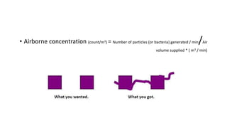

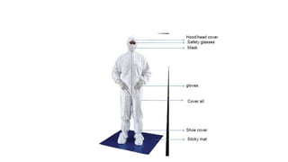
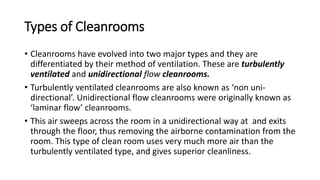
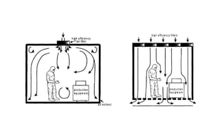
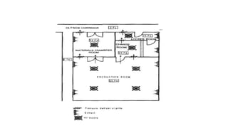
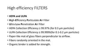
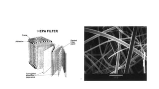
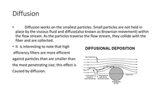
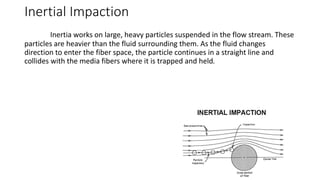
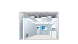
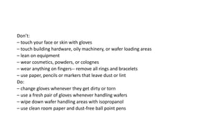


Clean room technology is used to control airborne particle concentrations and other parameters like temperature, humidity, and pressure. There are two main types of cleanrooms - turbulently ventilated and unidirectional flow. High efficiency particulate air (HEPA) and ultra low penetration air (ULPA) filters are used to filter air and control particle levels, working via mechanisms like diffusion, impaction, interception, and sieving. Proper clean room practices like changing gloves, wiping surfaces, and avoiding contaminants are important for maintaining cleanliness.


![[Deck] What's New in Spark-Iceberg Integration via DSV2.pptx](https://cdn.slidesharecdn.com/ss_thumbnails/deckwhatsnewinspark-icebergintegrationviadsv2-260210005337-25955b12-thumbnail.jpg?width=640&height=640&fit=bounds)


