


![R.M.K COLLEGE OF ENGG AND TECH / AQ / R2013/ ME6601 / VI / MECH / DEC 2017 – MAY 2018
ME6601 – DESIGN OF TRANSMISSION SYSTEM TWO MARKS QUESTION AND ANSWERS by
ASHOK KUMAR.R & ARUNKUMAR.S 6
UNIT – I – DESIGN OF FLEXIBLE ELEMENTS
PART - A
1.1) What is a power drive? Mention their types.
The power drive us a set of machine members employed to transmit power
or energy produced in one machine to another machine. The main type of power
drive are
Mechanical drive
Hydraulic drive
Pneumatic drive
Electrical drive
1.2) What is meant by mechanical drives?
The drives which transmits power by means of contact forces are called as
mechanical drives
1.3) Define Co-efficient of friction. [AU, Apr / May – 2018]
Coefficient of Friction (μ) is the ratio of the limiting force of friction (F)
and the normal Reaction (RN) between two surfaces.
𝜇 =
𝐹
𝑅 𝑁
1.4) What do you mean by angle of friction?
Angle of friction, ‘ϕ’ is the angle made by the resultant (R) of the normal
reaction (~) and the limiting force of friction (F) with the normal reaction (RN).
𝑡𝑎𝑛𝜙 = 𝜇 =
𝐹
𝑅 𝑁
1.5) State the law of belting.
Law of belting states that the centre line of the belt, as if approaches the
pulley lie in a plane perpendicular to the axis of that pulley or must lie in the plane
of the pulley otherwise the belt will run off the pulley.
1.6) Why are belt drives called as flexible drives?
A belt is a loop of flexible material used to link two or more rotating shafts
mechanically, most often parallel. Belts may be used as a source of motion, to
transmit power efficiently or to track relative movement.
1.7) What are the types of belts?](https://image.slidesharecdn.com/twomarksqusestionandanswersme6601dtsdec2018-190304141415/75/ME6601-DESIGN-OF-TRANSMISSION-SYSTEMS-TWO-MARK-QUESTION-ANSWERS-6-2048.jpg)
![R.M.K COLLEGE OF ENGG AND TECH / AQ / R2013/ ME6601 / VI / MECH / DEC 2017 – MAY 2018
ME6601 – DESIGN OF TRANSMISSION SYSTEM TWO MARKS QUESTION AND ANSWERS by
ASHOK KUMAR.R & ARUNKUMAR.S 7
Flat belt
V – belt
Circular belt or Rope
Multi groove belt
Timing belt
Ribbed belt
1.8) Name different types of belts. [AU, Nov / Dec – 2017]
Flat belt
V – belt
Circular belt or Rope
Multi groove belt
Timing belt
Ribbed belt
1.9) Name the four types of belts used for transmission of power.
[AU, Nov / Dec – 2018]
Flat belt
V – belt
Circular belt or Rope
Multi groove belt
Timing belt
Ribbed belt
1.10) What is meant by the ply of belt? [AU, Nov / Dec –2013]
The layer of belts is called as ply. The total number of belt layers used in
a belt is called number of plies. A number of layers of belt material is cemented
together to achieve the desired thickness of belt.
1.11) What is meant by ply in a flat belt? [AU, Apr / May – 2016]
The layer of belts is called as ply. The total number of belt layers used in
a belt is called number of plies. A number of layers of belt material is cemented
together to achieve the desired thickness of belt.
1.12) Mention the different types of joints employed for joining flat - belts.
Cemented Joint
Laced Joint](https://image.slidesharecdn.com/twomarksqusestionandanswersme6601dtsdec2018-190304141415/75/ME6601-DESIGN-OF-TRANSMISSION-SYSTEMS-TWO-MARK-QUESTION-ANSWERS-7-2048.jpg)
![R.M.K COLLEGE OF ENGG AND TECH / AQ / R2013/ ME6601 / VI / MECH / DEC 2017 – MAY 2018
ME6601 – DESIGN OF TRANSMISSION SYSTEM TWO MARKS QUESTION AND ANSWERS by
ASHOK KUMAR.R & ARUNKUMAR.S 8
Crest Joint
Hinged Joint
1.13) How the ends of flat are – belt joined? [AU, Apr / May – 2010]
Cemented Joint
Laced Joint
Crest Joint
Hinged Joint
Cemented joint: The cemented joint uses any cementing adhesive to form an endless belt.
Hinged joint: Metal hinges may be fastened to the belt ends and connected by a steel or fibre
pin.
Laced joint: In the laced joint, holes are punched across the belt, leaving a margin between
the edge and the holes.
A raw hide strip is used for lacing the two ends together to form a joint, this
form joint known as straight-stitch raw hide laced joint
Metal laced joint is made like a staple connection.
1.14) Mention the materials used for making belts. [AU, Nov / Dec – 2011]
Cotton or Fabric and Canvas
Leather
Rubber
Balata
Nylon core
1.15) Name the few materials for belt drives. [AU, Apr / May – 2016]
Cotton or Fabric and Canvas
Leather](https://image.slidesharecdn.com/twomarksqusestionandanswersme6601dtsdec2018-190304141415/75/ME6601-DESIGN-OF-TRANSMISSION-SYSTEMS-TWO-MARK-QUESTION-ANSWERS-8-2048.jpg)
![R.M.K COLLEGE OF ENGG AND TECH / AQ / R2013/ ME6601 / VI / MECH / DEC 2017 – MAY 2018
ME6601 – DESIGN OF TRANSMISSION SYSTEM TWO MARKS QUESTION AND ANSWERS by
ASHOK KUMAR.R & ARUNKUMAR.S 9
Rubber
Balata
Nylon core
1.16) What are the materials used for belt – drive? [AU, May / Jun – 2013]
Cotton or Fabric and Canvas
Leather
Rubber
Balata
Nylon core
1.17) Why should the tight - side of the belt be at the bottom side of the pulley?
[AU, Apr / May – 2005]
If the tight side of the belt is at the bottom side of the pulley, and the slack
side is at the top side, then the sag caused by the self-weight of belt, for long centre
distance drive will increases the arc od contact of belt with the pulley and hence the
effect of power transmission is increased. +
1.18) Differentiate open - belt drive and cross - belt drive.
Open Belt Drive Cross Belt Drive
Driving Shaft and drive shaft
rotate in same direction
Power transmission is low
compare to cross belt drive
Wear and tear is low
The angle of contact is less
compare to cross belt drive
Driving Shaft and drive shaft
rotate in same direction
Power transmission is high
compare to open belt drive
Wear and tear is high
The angle of contact is high
compare to open belt drive
1.19) Distinguish between open drive and cross drive of a belt drive. Which is
better? [AU, Apr / May – 2011]
Open Belt Drive Cross Belt Drive
Driving Shaft and drive shaft
rotate in same direction
Power transmission is low
compare to cross belt drive
Driving Shaft and drive shaft
rotate in same direction
Power transmission is high
compare to open belt drive](https://image.slidesharecdn.com/twomarksqusestionandanswersme6601dtsdec2018-190304141415/75/ME6601-DESIGN-OF-TRANSMISSION-SYSTEMS-TWO-MARK-QUESTION-ANSWERS-9-2048.jpg)
![R.M.K COLLEGE OF ENGG AND TECH / AQ / R2013/ ME6601 / VI / MECH / DEC 2017 – MAY 2018
ME6601 – DESIGN OF TRANSMISSION SYSTEM TWO MARKS QUESTION AND ANSWERS by
ASHOK KUMAR.R & ARUNKUMAR.S 10
Wear and tear is low
The angle of contact is less
compare to cross belt drive
Wear and tear is high
The angle of contact is high
compare to open belt drive
Except wear and tear crossed belt drive is better.
1.20) What is belt rating?
Flat belts are made of different sizes such as 3 ply, 4 ply and V belts are
made up of different grades such as A, B, C, D and E grade belts. Belt rating is
defined as the power transmitting capacity of unit size of flat belt or a particular
grade of V belt.
1.21) Why are thin wide flat belts preferred over thick narrow belts?
The thin wide belt possess more surface contact are with pulley that thick
narrow belt, thin belt can transmit more power than thick belt for a constant weight.
Hence thin wide belts are preferred.
1.22) A longer belt will last more than a shorter belt, why?[AU, Apr / May – 2017]
Longer belts reduces the bending radius of belt to a greater extent. This
reduces the fatigue and creep stress. Hence the belt life increases and will last more
than a shorter belt.
1.23) Briefly explain initial tension in belts.
The motion of belt and pulleys are governed by a firm grip between the
belt and pulley. In order to increase the grip for power transmission, the belt is
tightened up. Due to tightening the belt is subjected to tension is called as initial
tension
1.24) Give the expression for tension ratio in a belt drive.[AU, May / Jun – 2007]
𝑇1
𝑇2
= 𝑒 𝜇𝜃
T1 – Tension in tight side of the belt (N)
T2 – Tension in slack side of the belt (N)
– Angle of belt (radians)
– Coefficient of friction](https://image.slidesharecdn.com/twomarksqusestionandanswersme6601dtsdec2018-190304141415/75/ME6601-DESIGN-OF-TRANSMISSION-SYSTEMS-TWO-MARK-QUESTION-ANSWERS-10-2048.jpg)
![R.M.K COLLEGE OF ENGG AND TECH / AQ / R2013/ ME6601 / VI / MECH / DEC 2017 – MAY 2018
ME6601 – DESIGN OF TRANSMISSION SYSTEM TWO MARKS QUESTION AND ANSWERS by
ASHOK KUMAR.R & ARUNKUMAR.S 11
1.25) Give an expression for ratio of tensions in a flat belt drive.
[AU, Nov / Dec –2012]
𝑇1
𝑇2
= 𝑒 𝜇𝜃
T1 – Tension in tight side of the belt (N)
T2 – Tension in slack side of the belt (N)
– Angle of belt (radians)
– Coefficient of friction
1.26) What is the condition to transmit maximum power in a flat belt drive?
[AU, Nov / Dec – 2016, 2018]
The condition to transmit maximum power in flat belt drive is
𝐵𝑒𝑙𝑡 𝑉𝑒𝑙𝑜𝑐𝑖𝑡𝑦 = 𝑣 = √
𝑇 𝑚𝑎𝑥
3𝑚
𝑇 𝑚𝑎𝑥 = 3𝑇𝐶
Tmax – Maximum permissible tension (N)
TC – Centrifugal tension of the belt (N)
m – Mass of belt per unit length (kg/m)
1.27) Why tight – side of the belt should be at the bottom side of the pulley?
[AU, Nov / Dec –2004, May / Jun – 2006]
If the tight side is at bottom so the slack side will increase the arc of
contact at the pulley at top. The increase in arc of contact will increase in power
transmitting capacity.
1.28) What will be the effect on the limiting ratio of tensions of a belt if the co-
efficient of friction between the belt and rim of pulley is doubled while angle of
lap remains the same? [AU, Nov / Dec –2007]
The tension ratio
𝑇1
𝑇2
= 𝑒 𝜇𝜃
T1 – Tension in tight side of the belt (N)
T2 – Tension in slack side of the belt (N)
– Angle of belt (radians)
– Coefficient of friction](https://image.slidesharecdn.com/twomarksqusestionandanswersme6601dtsdec2018-190304141415/75/ME6601-DESIGN-OF-TRANSMISSION-SYSTEMS-TWO-MARK-QUESTION-ANSWERS-11-2048.jpg)
![R.M.K COLLEGE OF ENGG AND TECH / AQ / R2013/ ME6601 / VI / MECH / DEC 2017 – MAY 2018
ME6601 – DESIGN OF TRANSMISSION SYSTEM TWO MARKS QUESTION AND ANSWERS by
ASHOK KUMAR.R & ARUNKUMAR.S 12
If coefficient of friction () is doubled. Then tension ratio will be
𝑇1
𝑇2
= 𝑒2𝜇𝜃
= [𝑒 𝜇𝜃
]
2
The new ratio of tensions will be square of the original ratio.
1.29) What are the various losses in the power transmission by belts?
[AU, Nov / Dec –2005, 2008]
Speed losses due to the slip and creep that occur in belt when
running over pulleys.
Friction losses in the interface of belt and pulley
Windage losses as the belt moves through the air
Power loss in the form of heat generated due to the combined losses
1.30) Mention the losses in belt drives. [AU, Nov / Dec –2014]
Speed losses due to the slip and creep that occur in belt when
running over pulleys.
Friction losses in the interface of belt and pulley
Windage losses as the belt moves through the air
Power loss in the form of heat generated due to the combined losses
1.31) Why is the face of a pulley crowned? [AU, Nov / Dec –2009]
The crowning tends to keep the belt in centre on a pulley rim while in
motion. The height of the crown depends upon the width, speed and length of belt.
1.32) Define the term "crowning of pulley". [AU, Nov / Dec – 2016]
Crowning in pulley is the process of providing slight downward taper from
the centre towards the ends in the pulley top surface. This increases the frictional
resistance and prevents the slip of the belt from the pulley. The crowning tends to
keep the belt in centre on a pulley rim while in motion. The height of the crown
depends upon the width, speed and length of belt.](https://image.slidesharecdn.com/twomarksqusestionandanswersme6601dtsdec2018-190304141415/75/ME6601-DESIGN-OF-TRANSMISSION-SYSTEMS-TWO-MARK-QUESTION-ANSWERS-12-2048.jpg)
![R.M.K COLLEGE OF ENGG AND TECH / AQ / R2013/ ME6601 / VI / MECH / DEC 2017 – MAY 2018
ME6601 – DESIGN OF TRANSMISSION SYSTEM TWO MARKS QUESTION AND ANSWERS by
ASHOK KUMAR.R & ARUNKUMAR.S 13
1.33) Explain the term crowning of pulley.
[AU, Apr / May – 2005, May / Jun – 2011]
Crowning in pulley is the process of providing slight downward taper from
the centre towards the ends in the pulley top surface. This increases the frictional
resistance and prevents the slip of the belt from the pulley. The crowning tends to
keep the belt in centre on a pulley rim while in motion. The height of the crown
depends upon the width, speed and length of belt.
1.34) Brief the term "Crowning of Pulley [AU, May / Jun – 2014]
Crowning in pulley is the process of providing slight downward taper from
the centre towards the ends in the pulley top surface. This increases the frictional
resistance and prevents the slip of the belt from the pulley. The crowning tends to
keep the belt in centre on a pulley rim while in motion. The height of the crown
depends upon the width, speed and length of belt.](https://image.slidesharecdn.com/twomarksqusestionandanswersme6601dtsdec2018-190304141415/75/ME6601-DESIGN-OF-TRANSMISSION-SYSTEMS-TWO-MARK-QUESTION-ANSWERS-13-2048.jpg)
![R.M.K COLLEGE OF ENGG AND TECH / AQ / R2013/ ME6601 / VI / MECH / DEC 2017 – MAY 2018
ME6601 – DESIGN OF TRANSMISSION SYSTEM TWO MARKS QUESTION AND ANSWERS by
ASHOK KUMAR.R & ARUNKUMAR.S 14
1.35) What is crowning of pulley? Specify the purpose of crowning of pulley.
[AU, May / Jun – 2006]
Crowning in pulley is the process of providing slight downward taper from
the centre towards the ends in the pulley top surface. This increases the frictional
resistance and prevents the slip of the belt from the pulley. The crowning tends to
keep the belt in centre on a pulley rim while in motion. The height of the crown
depends upon the width, speed and length of belt.
1.36) What is the effect of centre distance and diameter of pulley on the life of a
belt? [AU, Nov / Dec –2005]
The increased centre distance and higher pulley diameters reduce the
bending radii of belts to a greater extent. This results in reduced fatigue and creep.
Hence, the belt life increases.
1.37) Define creep in belt. What is its effect on the speed?
The slow movement of the belt; moving back slightly relative to the
driving pulley and forward slightly relative to the driven pulley due to unequal
stretching of the belt in the tight side and slack side of the belt drive in operation is
known as creep.](https://image.slidesharecdn.com/twomarksqusestionandanswersme6601dtsdec2018-190304141415/75/ME6601-DESIGN-OF-TRANSMISSION-SYSTEMS-TWO-MARK-QUESTION-ANSWERS-14-2048.jpg)
![R.M.K COLLEGE OF ENGG AND TECH / AQ / R2013/ ME6601 / VI / MECH / DEC 2017 – MAY 2018
ME6601 – DESIGN OF TRANSMISSION SYSTEM TWO MARKS QUESTION AND ANSWERS by
ASHOK KUMAR.R & ARUNKUMAR.S 15
The effect of creep back on the driving pulley is to slow down the speed of
the belt with respect to driving pulley. The effect of creep forward on the driven
pulley is to slow down the speed of driven pulley as a result, the speed ratio is
reduced
1.38) State the reasons for V – belt drive being preferred to flat belt drive?
[AU, Nov / Dec –2010]
Replacement of V – belt is easy, because V belts are available
according to standards.
Power transmitted by the V – belts is more.
For smaller centre distances V – belts are more suitable
Efficiency is high compared to flat belt.
1.39) Write the disadvantages of flat belt drive. [AU, Nov / Dec –2015]
It is a non-positive drive and hence, slip and creep occur.
Requires more space.
Angular velocity ratio is not necessarily constant or equal to the ratio of
pulley diameters, because of slipping and stretching.
Heat build-up occurs.
Speed is limited.
Power transmission is limited.
1.40) What is a slack adjuster? [AU, Nov / Dec –2004]
Slack adjuster is a movable device used for adjusting the slack/ tension in a
belt drive. By this, the tension is adjusted so that the required initial tension T0 is
maintained in the belt drive.
This is usually done in two ways:
By adjusting the centre distance between the pulleys
By introducing an idler pulley that presses against the belt to adjust the
tension
1.41) Write the different types of pulleys used in belt drives.
Solid Pulley
Split pulley
Stepped or cone pulley](https://image.slidesharecdn.com/twomarksqusestionandanswersme6601dtsdec2018-190304141415/75/ME6601-DESIGN-OF-TRANSMISSION-SYSTEMS-TWO-MARK-QUESTION-ANSWERS-15-2048.jpg)
![R.M.K COLLEGE OF ENGG AND TECH / AQ / R2013/ ME6601 / VI / MECH / DEC 2017 – MAY 2018
ME6601 – DESIGN OF TRANSMISSION SYSTEM TWO MARKS QUESTION AND ANSWERS by
ASHOK KUMAR.R & ARUNKUMAR.S 16
1.42) When is a split pulley used? How is it tightened on a shaft?
Split pulley are used in flat belt, line shaft applications. The split pulley is
tightened to shaft with bolt and nut.
1.43) When do you use stepped pulley drive?
[AU, Apr / May – 2016, Nov / Dec – 2018]
Stepped pulley drive is used when the speed of the driven shaft is to be
changed very frequently as in case of machine tools such as lathe, drilling machine
etc. A stepped pulley is an integral casting having three or more number of pulleys
of different diameter
1.44) What are the factors upon which the coefficient of friction between the belt
and pulley depends? [AU, May / Jun – 2014]
Material of the belt
Material of the pulley
Speed of the belt
Nature of contact surfaces between the belt and the pulleys.
1.45) Sketch the cross - section of a V- belt and label its important parts.
[AU, Nov / Dec –2009]](https://image.slidesharecdn.com/twomarksqusestionandanswersme6601dtsdec2018-190304141415/75/ME6601-DESIGN-OF-TRANSMISSION-SYSTEMS-TWO-MARK-QUESTION-ANSWERS-16-2048.jpg)
![R.M.K COLLEGE OF ENGG AND TECH / AQ / R2013/ ME6601 / VI / MECH / DEC 2017 – MAY 2018
ME6601 – DESIGN OF TRANSMISSION SYSTEM TWO MARKS QUESTION AND ANSWERS by
ASHOK KUMAR.R & ARUNKUMAR.S 17
1.46) How is a V - belt specified? [AU, May / Jun – 2012, Nov / Dec –2012]
V-belts are designated by their cross section symbol (A, B, C, D or E)
followed by its nominal inside length in mm.
Example: C 3048/120- The belt cross section is 'C, and nominal inside length is
3048 mm (120 inches).
1.47) What are the advantages of V belt drive? [AU, Nov / Dec –2012]
High power transmission capacity because V-grooves provide excellent
grip.
The functioning of the belt and the pulley is smooth and quiet.
The V-belt drive provides compactness due to the small distance
between the centers of the pulleys.
Slip between the belt and the pulley is negligible.
The axis can be horizontal, vertical or inclined.
They can dampen vibration.
1.48) What are the advantages and disadvantages of V - belt drive over flat belt
drive? [AU, May / Jun – 2011]
Advantages:
Negligible slip due to wedging action between the belt and V-groove
pulley
Require little pretension
Compact design and smooth operation
High velocity ratio.
Can transmit more power for the same coefficient of friction.
V-belt can run even the belt is vertical.
Disadvantages:
The V-belt drive cannot be used for long distances due to greater
weight per unit of length.
They are not applicable to the synchronous machines because they are
not free from creep.
The centrifugal tension prevents the use of belts at speeds below 5 m/s
and above 50 m/s.](https://image.slidesharecdn.com/twomarksqusestionandanswersme6601dtsdec2018-190304141415/75/ME6601-DESIGN-OF-TRANSMISSION-SYSTEMS-TWO-MARK-QUESTION-ANSWERS-17-2048.jpg)
![R.M.K COLLEGE OF ENGG AND TECH / AQ / R2013/ ME6601 / VI / MECH / DEC 2017 – MAY 2018
ME6601 – DESIGN OF TRANSMISSION SYSTEM TWO MARKS QUESTION AND ANSWERS by
ASHOK KUMAR.R & ARUNKUMAR.S 18
The construction of pulleys for V-belts is more complicated than flat
belt.
1.49) Write the advantages of V - belt over flat belt. [AU, Nov / Dec – 2017]
Negligible slip due to wedging action between the belt and V-groove
pulley
Require little pretension
Compact design and smooth operation
High velocity ratio.
Can transmit more power for the same coefficient of friction.
V-belt can run even the belt is vertical.
1.50) Mention the disadvantages of V belts over flat belts. [AU, May / Jun – 2012]
The V-belt drive cannot be used for long distances due to greater
weight per unit of length.
They are not applicable to the synchronous machines because they are
not free from creep.
The centrifugal tension prevents the use of belts at speeds below 5 m/s
and above 50 m/s.
The construction of pulleys for V-belts is more complicated than flat
belt.
1.51) In what ways are the timing belts superior to ordinary V belts?
[AU, May / Jun – 2006, 2007, Apr / May – 2015]
The timing belt has cogs and hence, there will not be any slip.
In the absence of slip, timing belt maintains exact speed ratio.
Less maintenance.
No initial tension required.
1.52) Give the relationship of ratio of tensions in a V-belt drive.
[AU, Apr / May – 2008]
𝑇1
𝑇2
= 𝑒
(
𝜇𝜃
𝑠𝑖𝑛𝛽
)
Where T1 & T2 – Tensions on the tight side and slack side
μ - Coefficient of friction
θ - Angle of contact (lap)](https://image.slidesharecdn.com/twomarksqusestionandanswersme6601dtsdec2018-190304141415/75/ME6601-DESIGN-OF-TRANSMISSION-SYSTEMS-TWO-MARK-QUESTION-ANSWERS-18-2048.jpg)
![R.M.K COLLEGE OF ENGG AND TECH / AQ / R2013/ ME6601 / VI / MECH / DEC 2017 – MAY 2018
ME6601 – DESIGN OF TRANSMISSION SYSTEM TWO MARKS QUESTION AND ANSWERS by
ASHOK KUMAR.R & ARUNKUMAR.S 19
β - Groove angle
1.53) Why slip is less in the case of V – belts when compared with flat belts?
[AU, May / Jun – 2013]
The wedging action between the V-belt and V-pulleys permits small arc
of contact.
This wedging action reduces belt slip when compared to flat belt.
As a result, the power transmission capacity is increased
1.54) Define maximum tension in a belt. [AU, Apr / May – 2008]
The maximum tension in the belt is the tension on the tight side. That is,
TMax = T1
If centrifugal tension, Tc is not significant and hence not considered
TMax = T1 + Tc
If centrifugal tension is considered
1.55) What is centrifugal effect on belts? [AU, Nov / Dec –2015]
When the belt with a significant mass runs at reasonably higher speed (>10
m/s) over a pulley, it experiences a centrifugal force acting radially outwards. This
tension caused in the running belt by the centrifugal force is known as the
centrifugal tension.
Tc = m * v2
; where,
m - mass of the belt per metre length,
m = (Density of Belt Material * Belt Width * Belt Thickness)
v - linear velocity of the belt, m/s.
Centrifugal tension increases both the tensions at the tight side and slack
side. However, the centrifugal tension has no impact on the power transmission
1.56) Give the condition for maximum power transmission in terms of
centrifugal tension in case of belt drive. [AU, May / Jun – 2009, 2011]
The condition to transmit maximum power in a flat belt drive is:
Belt Velocity,𝑣 = √
𝑇 𝑚𝑎𝑥
3𝑚
m - mass of belt per unit length, kg/m.
Maximum Permissible Tension, Tmax = 3Tc
Tension on Tight Side, T1 = 2Tc](https://image.slidesharecdn.com/twomarksqusestionandanswersme6601dtsdec2018-190304141415/75/ME6601-DESIGN-OF-TRANSMISSION-SYSTEMS-TWO-MARK-QUESTION-ANSWERS-19-2048.jpg)
![R.M.K COLLEGE OF ENGG AND TECH / AQ / R2013/ ME6601 / VI / MECH / DEC 2017 – MAY 2018
ME6601 – DESIGN OF TRANSMISSION SYSTEM TWO MARKS QUESTION AND ANSWERS by
ASHOK KUMAR.R & ARUNKUMAR.S 20
1.57) What are the five parts of roller chain? [AU, Apr / May – 2010]
The important elements in a roller chain are:
Pin
Bushing
Roller
Inner link plate
Outer link plate.
1.58) Specify the five parts of roller chain. [AU, Nov / Dec –2011]
The important elements in a roller chain are:
Pin
Bushing
Roller
Inner link plate
Outer link plate.
1.59) What do you mean by galling of roller chains? [AU, Nov / Dec –2010]
Galling is a stick-slip phenomenon between the pin and bushing.
When the chain tension is high due to heavy loads and high chain speeds,
micro welds are formed at the high spots of the contact area.
Such microscopic welds are immediately broken due to the relative
motion between the contact surfaces.
This results in excessive wear even in the presence of lubrication.
This abnormal wear is known as Galling.
1.60) Mention the materials used for making link plates in chain drives.
[AU, May / Jun – 2012]
The materials used for link plates are
Alloy steels C45, C50 and 40Crl.
Medium carbon steel
1.61) What is chordal action in chain drives? [AU, Nov / Dec –2015]
When chain passes over a sprocket, it moves as a series of chords instead
of a continuous arc as in the case of a belt drive. This results in varying speed of
the chain drive. This phenomenon is known as Polygonal Effect (or) Chordal](https://image.slidesharecdn.com/twomarksqusestionandanswersme6601dtsdec2018-190304141415/75/ME6601-DESIGN-OF-TRANSMISSION-SYSTEMS-TWO-MARK-QUESTION-ANSWERS-20-2048.jpg)
![R.M.K COLLEGE OF ENGG AND TECH / AQ / R2013/ ME6601 / VI / MECH / DEC 2017 – MAY 2018
ME6601 – DESIGN OF TRANSMISSION SYSTEM TWO MARKS QUESTION AND ANSWERS by
ASHOK KUMAR.R & ARUNKUMAR.S 21
Action. In order to reduce the chordal effect, the number of teeth on the sprocket
should be increased.
1.62) What is meant by chordal action in chain drives?
[AU, Apr / May – 2004, 2010]
When chain passes over a sprocket, it moves as a series of chords instead
of a continuous arc as in the case of a belt drive. This results in varying speed of
the chain drive. This phenomenon is known as Polygonal Effect (or) Chordal
Action. In order to reduce the chordal effect, the number of teeth on the sprocket
should be increased.
1.63) What is meant by chordal action of chain? Also name a company that
produces driving chains. [AU, Apr / May – 2015, May / Jun – 2006]
When chain passes over a sprocket, it moves as a series of chords instead
of a continuous arc as in the case of a belt drive. This results in varying speed of
the chain drive. This phenomenon is known as Polygonal Effect (or) Chordal
Action. In order to reduce the chordal effect, the number of teeth on the sprocket
should be increased.
Companies that manufacture driving chains:
Renold India, Gudalur, Tamilnadu.
TIDC India Ltd., Ambattur, Tamilnadu.
Galaxy Chains Pvt. Ltd., Rajkot, Gujarat.
1.64) What is done to accommodate initial sag in chain drive?
[AU, May / Jun – 2007]
In order to accommodate initial sag in the chain, the value of the centre
distance, 'a' should be decreased by [0.01 * a] (or) 2 to 5 mm.
1.65) What factors will affect the working conditions of the chain drive?
[AU, Nov / Dec – 2016]
The factors affecting the working conditions of the chain drive are:
Type of loading: constant (or) variable.
Centre distance between the shafts
Position of driving shaft: horizontal (or) inclined.
Nature of lubrication: continuous, drop (or) periodic.
Service: continuous (or) fixed no. of hours per day.](https://image.slidesharecdn.com/twomarksqusestionandanswersme6601dtsdec2018-190304141415/75/ME6601-DESIGN-OF-TRANSMISSION-SYSTEMS-TWO-MARK-QUESTION-ANSWERS-21-2048.jpg)
![R.M.K COLLEGE OF ENGG AND TECH / AQ / R2013/ ME6601 / VI / MECH / DEC 2017 – MAY 2018
ME6601 – DESIGN OF TRANSMISSION SYSTEM TWO MARKS QUESTION AND ANSWERS by
ASHOK KUMAR.R & ARUNKUMAR.S 22
Operating environment: corrosive (or) dirty.
1.66) List the chain drive failures. [AU, Nov / Dec – 2017]
Overload- chain subjected to excessive one-off load which causes
permanent deformation of material and leads to very short chain life.
Fatigue- chain subjected to repetitive high load beyond the endurance
limit, causing it to eventually fracture.
Wear- Load normally between pin and bush eventually wears away
material such that the chain stretches beyond its usable limit. Most chain
are designed to fail due to wear.
Galling - Lack of lubrication or excessively high running loads. Metal to
metal welding. Smeared and grooved surface. This pin is also corroded.
1.67) In chain drives, the sprocket has odd number of teeth and the chain has
even number of links. Why? [AU, Nov / Dec –2012]
In order to have uniform wear on all the links, it is preferable to have odd
number of teeth on the smaller sprocket and an even number of pitches in the
chain.](https://image.slidesharecdn.com/twomarksqusestionandanswersme6601dtsdec2018-190304141415/75/ME6601-DESIGN-OF-TRANSMISSION-SYSTEMS-TWO-MARK-QUESTION-ANSWERS-22-2048.jpg)
![R.M.K COLLEGE OF ENGG AND TECH / AQ / R2013/ ME6601 / VI / MECH / DEC 2017 – MAY 2018
ME6601 – DESIGN OF TRANSMISSION SYSTEM TWO MARKS QUESTION AND ANSWERS by
ASHOK KUMAR.R & ARUNKUMAR.S 23
1.68) What are the advantages of chain drives? [AU, Apr / May – 2018]
Chain drives has more power transmitting capacity
Higher efficiency and compact size
Except less load on shaft since no initial tension is applied on the
sprocket
1.69) Give any three applications of chain drives. What are their limitations?
[AU, Apr / May – 2011]
Applications:
Chain drives are used in many types of industrial applications, such
as:
Rigging and moving heavy materials
Hydraulic lift truck fork operation
Overhead hoists
Operating conveyer belts.
Limitations:
The production cost of chains is relatively high.
The chain drive needs accurate mounting and careful
maintenance, particularly lubrication and slack adjustment.
The chain drive has velocity fluctuations especially when
unduly stretched
Cannot be used in applications where the drive must slip
Are noisy and can cause vibrations
Do not have the load capacity or service life of gear drives
1.70) Give the advantages of chain drives over belt drives. [AU, May / Jun – 2012]
For the transmission of more power over a longer as well as shorter
distances.
Compact than belt drives.
Slip is less compared to belt drive.
1.71) Under what circumstances chain drives are preferred over V belt drives?
[AU, Apr / May – 2016]
Chain drives are preferred over V-belt drives under the following
conditions:](https://image.slidesharecdn.com/twomarksqusestionandanswersme6601dtsdec2018-190304141415/75/ME6601-DESIGN-OF-TRANSMISSION-SYSTEMS-TWO-MARK-QUESTION-ANSWERS-23-2048.jpg)
![R.M.K COLLEGE OF ENGG AND TECH / AQ / R2013/ ME6601 / VI / MECH / DEC 2017 – MAY 2018
ME6601 – DESIGN OF TRANSMISSION SYSTEM TWO MARKS QUESTION AND ANSWERS by
ASHOK KUMAR.R & ARUNKUMAR.S 24
For the transmission of more power over a longer as well as shorter
distances.
Where higher speeds and more accurate speed ratio are required.
They can be operated under adverse temperature and atmospheric
conditions.
They can transmit power to several shafts by one chain.
1.72) What do you understand by simplex, duplex and triplex chains?
[AU, May / Jun – 2007]
Simplex chain consists of length of single links (single strand), duplex is
length of double links (double strands) and triplex is length of triple links (triple
strands). From PSGDDB @ 7.71 Chain numbers with prefix R & B denote
simplex, DR & DB denote duplex and TR & TB denote triplex chains.
1.73) In what way is a silent chain better than an ordinary driving chain?
[AU, Apr / May – 2005, Nov / Dec –2008, May / Jun – 2011]
Silent (or) inverted tooth chain is a type of chain with teeth formed on its
links to engage with the teeth in the sprockets.
Advantages:
Operate with less vibrations and noise.
They can be installed without dismantling drive components.
They can be used in varying temperature ranges.
Higher speed and power transmitting capacity
Greater efficiency.](https://image.slidesharecdn.com/twomarksqusestionandanswersme6601dtsdec2018-190304141415/75/ME6601-DESIGN-OF-TRANSMISSION-SYSTEMS-TWO-MARK-QUESTION-ANSWERS-24-2048.jpg)
![R.M.K COLLEGE OF ENGG AND TECH / AQ / R2013/ ME6601 / VI / MECH / DEC 2017 – MAY 2018
ME6601 – DESIGN OF TRANSMISSION SYSTEM TWO MARKS QUESTION AND ANSWERS by
ASHOK KUMAR.R & ARUNKUMAR.S 25
1.74) What is a silent chain? In what situations, silent chains are preferred?
[AU, Nov / Dec –2007]
Silent (or) inverted tooth chain is a type of chain with teeth formed on its
links to engage with the teeth in the sprockets.
Advantages:
Operate with less vibrations and noise.
They can be installed without dismantling drive components.
They can be used in varying temperature ranges.
Higher speed and power transmitting capacity
Greater efficiency.
1.75) Sketch and name the different types of compound wire ropes.
[AU, Apr / May – 2004, 2010]
Regular lay ropes - Strands rotate around the rope in the opposite
direction to the wires of the strand.
Lang lay ropes - The Strands rotate around the rope in the same direction
to the wires of the strand.
Alternate lay ropes - Here, the rope is constructed using alternate strands
of right regular lay and right lang lay.](https://image.slidesharecdn.com/twomarksqusestionandanswersme6601dtsdec2018-190304141415/75/ME6601-DESIGN-OF-TRANSMISSION-SYSTEMS-TWO-MARK-QUESTION-ANSWERS-25-2048.jpg)
![R.M.K COLLEGE OF ENGG AND TECH / AQ / R2013/ ME6601 / VI / MECH / DEC 2017 – MAY 2018
ME6601 – DESIGN OF TRANSMISSION SYSTEM TWO MARKS QUESTION AND ANSWERS by
ASHOK KUMAR.R & ARUNKUMAR.S 26
1.76) How the wire ropes are designated? [AU, Nov / Dec – 2016, 2018]
Wire ropes are designated by the no. of strands & the no. of wires in each
strand. Example: Wire rope, 7 x 19 means: The wire rope has 7 Strands and each
Strand has 19 wires each.
1.77) How is a wire - rope designated? [AU, May / Jun – 2007]
Wire ropes are designated by the no. of strands & the no. of wires in each
strand. Example: Wire rope, 7 x 19 means: The wire rope has 7 Strands and each
Strand has 19 wires each.
1.78) How is a wire rope specified? [AU, May / Jun – 2009]
Wire ropes are designated by the no. of strands & the no. of wires in each
strand. Example: Wire rope, 7 x 19 means: The wire rope has 7 Strands and each
Strand has 19 wires each.
1.79) What kind of stresses should be considered during the selection of wire -
ropes?
The stresses that act on a rope are:
Direct tensile stress due to load and self weight](https://image.slidesharecdn.com/twomarksqusestionandanswersme6601dtsdec2018-190304141415/75/ME6601-DESIGN-OF-TRANSMISSION-SYSTEMS-TWO-MARK-QUESTION-ANSWERS-26-2048.jpg)
![R.M.K COLLEGE OF ENGG AND TECH / AQ / R2013/ ME6601 / VI / MECH / DEC 2017 – MAY 2018
ME6601 – DESIGN OF TRANSMISSION SYSTEM TWO MARKS QUESTION AND ANSWERS by
ASHOK KUMAR.R & ARUNKUMAR.S 27
Bending stress due to the bending of rope round the drum and,
Stresses due to speed changes, starting and stopping.
1.80) What do you understand by 6 x 19 construction in wire ropes?
[AU, Nov / Dec –2014]
Wire rope, 6 x 19 means: The wire rope has 6 Strands and each Strand has
19 wires each.
1.81) Write any four wire rope applications. [AU, Nov / Dec –2013]
Used in mines, tram ways and power transmission
Used in hoisting equipment like cranes, elevators
Used in hand operated hoisting machinery and as ropes for fitting
tackles hooks etc.
1.82) List the advantages of wire ropes compared to chains.
[AU, Apr / May – 2017]
The metal chains can handle a large load, if one link in that chain breaks or
suffers a defect, then the whole length of the chain is rendered useless. If wires or a
strand within a rope break or snap, the load can still be supported by the rest of the
strands, especially the strong core.
1.83) What are the advantages of belt drives in compare with that of the chain
and rope drives? [AU, Nov / Dec – 2017]
The metal chains can handle a large load, if one link in that chain breaks or
suffers a defect, then the whole length of the chain is rendered useless. If wires or a
strand within a rope break or snap, the load can still be supported by the rest of the
strands, especially the strong core.](https://image.slidesharecdn.com/twomarksqusestionandanswersme6601dtsdec2018-190304141415/75/ME6601-DESIGN-OF-TRANSMISSION-SYSTEMS-TWO-MARK-QUESTION-ANSWERS-27-2048.jpg)
![R.M.K COLLEGE OF ENGG AND TECH / AQ / R2013/ ME6601 / VI / MECH / DEC 2017 – MAY 2018
ME6601 – DESIGN OF TRANSMISSION SYSTEM TWO MARKS QUESTION AND ANSWERS by
ASHOK KUMAR.R & ARUNKUMAR.S 28
UNIT – II – SPUR GEARS AND PARALLEL AXIS HELICAL GEARS
Part – A
2.1) What is a gear drive?
Gear drive is a mechanism consisting of toothed wheels that engage and
transmit rotary motion, usually transforming angular velocity and torques.
2.2) Enumerate the advantages and disadvantages of gear - drives over flexible
drives.
Advantages:
By using gear trains, large velocity ratio can be obtained with
minimum space.
Gears are mechanically strong, so higher loads can be lifted.
They are used for transmitting motion over small centre distance of
shafts
They are used for large reduction in speed and for transmission of
torque.
Gears require only lubrication, hence less maintenance is required.
Using gear systems, we can transmit motion between non-parallel
intersecting shafts.
They have long life, so the gear system is very compact.
Disadvantages:
They are not suitable for large velocities.
They are not suitable for transmitting motion over a large distance.
Due to the engagement of toothed wheel of gears, some part of
machine may get permanently damaged in case of excessive
loading.
They have no flexibility.
Gear operation is noisy.
2.3) State the advantages of toothed gears over the other types of transmission
systems. [AU, Nov / Dec – 2018]
By using gear trains, large velocity ratio can be obtained with
minimum space.
Gears are mechanically strong, so higher loads can be lifted.](https://image.slidesharecdn.com/twomarksqusestionandanswersme6601dtsdec2018-190304141415/75/ME6601-DESIGN-OF-TRANSMISSION-SYSTEMS-TWO-MARK-QUESTION-ANSWERS-28-2048.jpg)
![R.M.K COLLEGE OF ENGG AND TECH / AQ / R2013/ ME6601 / VI / MECH / DEC 2017 – MAY 2018
ME6601 – DESIGN OF TRANSMISSION SYSTEM TWO MARKS QUESTION AND ANSWERS by
ASHOK KUMAR.R & ARUNKUMAR.S 29
They are used for transmitting motion over small centre distance of
shafts
They are used for large reduction in speed and for transmission of
torque.
Gears require only lubrication, hence less maintenance is required.
Using gear systems, we can transmit motion between non-parallel
intersecting shafts.
They have long life, so the gear system is very compact.
2.4) How are gears classified?
Parallel Axes Gears
Spur Gear
Spur rack
Internal gear
Helical gear
Helical rack
Double helical gear
Intersecting Axes Gears
Straight bevel gear
Spiral bevel gear
Zerol bevel gear
Nonparallel and Nonintersecting
Screw gear
Worm gear
2.5) Label a) addendum b) flank in a simple sketch of a gear tooth.
[AU, May / Jun – 2007]](https://image.slidesharecdn.com/twomarksqusestionandanswersme6601dtsdec2018-190304141415/75/ME6601-DESIGN-OF-TRANSMISSION-SYSTEMS-TWO-MARK-QUESTION-ANSWERS-29-2048.jpg)
![R.M.K COLLEGE OF ENGG AND TECH / AQ / R2013/ ME6601 / VI / MECH / DEC 2017 – MAY 2018
ME6601 – DESIGN OF TRANSMISSION SYSTEM TWO MARKS QUESTION AND ANSWERS by
ASHOK KUMAR.R & ARUNKUMAR.S 30
2.6) Specify the types of gear - failures. [AU, Apr / May – 2018]
2.7) What are the main types of gear tooth failure? [AU, May / Jun – 2013, 2016]](https://image.slidesharecdn.com/twomarksqusestionandanswersme6601dtsdec2018-190304141415/75/ME6601-DESIGN-OF-TRANSMISSION-SYSTEMS-TWO-MARK-QUESTION-ANSWERS-30-2048.jpg)
![R.M.K COLLEGE OF ENGG AND TECH / AQ / R2013/ ME6601 / VI / MECH / DEC 2017 – MAY 2018
ME6601 – DESIGN OF TRANSMISSION SYSTEM TWO MARKS QUESTION AND ANSWERS by
ASHOK KUMAR.R & ARUNKUMAR.S 31
2.8) Mention the advantages of non – metallic gears? [AU, Nov / Dec –2012]
Require minimum (or) no lubrication
Less noise, less wear, reduced vibrations and shocks during operation.
Light weight and minimum maintenance
Can operate at high speeds.
Longer life
Resistant to corrosion. Not affected by water and oil.
2.9) Mention the disadvantages of non-metallic gears. [AU, Nov / Dec –2011]
Less load-carrying capacity compared to similarly sized metal gears.
Molded gears cannot hold the same high tolerances that metal gears can.
Plastic is less dimensionally stable when compared to metal and this
results in dimensional variations due to temperature and humidity
conditions.
Material cost is significantly higher than that of base metals and can vary
widely due to fluctuations in the cost of base chemicals.
Difficulty in attaching plastic gears to metal shafts.
2.10) Specify the significance of minimum number of teeth in pinions.
[AU, May / Jun – 2012]
The minimum number of teeth in pinion is important to avoid interference
and undercutting.
2.11) What condition must be satisfied in order that a pair of spur gears may
have a constant velocity ratio? [AU, Nov / Dec –2009, May / Jun – 2014]
It should satisfy the law of gearing.
Law of gearing states that, in order to maintain a constant angular
velocity ratio between two meshing gears, the common normal of the
tooth profiles, at all contact points within mesh, should always pass
through a fixed point on the line of centers, called the pitch point.
2.12) What is meant by pressure angle? [AU, May / Jun – 2006]
The Pressure Angle is the acute angle between the line of action and a
normal to the line connecting the gear centers.](https://image.slidesharecdn.com/twomarksqusestionandanswersme6601dtsdec2018-190304141415/75/ME6601-DESIGN-OF-TRANSMISSION-SYSTEMS-TWO-MARK-QUESTION-ANSWERS-31-2048.jpg)
![R.M.K COLLEGE OF ENGG AND TECH / AQ / R2013/ ME6601 / VI / MECH / DEC 2017 – MAY 2018
ME6601 – DESIGN OF TRANSMISSION SYSTEM TWO MARKS QUESTION AND ANSWERS by
ASHOK KUMAR.R & ARUNKUMAR.S 32
2.13) What is pressure angle? What is the effect of increase in pressure angle?
[AU, May / Jun – 2006, 2014, Apr / May – 2015]
The Pressure Angle is the acute angle between the line of action and a
normal to the line connecting the gear centers.
The effects of increasing the pressure angle are:
Higher pressure angle improves the tooth strength.
Increasing pressure angle results in smaller base circle so more
portion of tooth becomes involute thus can eliminate interference.
Increasing pressure angle will improve power transmission but, at
the same time will increase gear wear and meshing noise.
2.14) What is the effect of increase in pressure angle? [AU, Apr / May – 2005]
Higher pressure angle improves the tooth strength.
Increasing pressure angle results in smaller base circle so more portion
of tooth becomes involute thus can eliminate interference.
Increasing pressure angle will improve power transmission but, at the
same time will increase gear wear and meshing noise.
2.15) What is the effect of increasing the pressure angle in gears?
[AU, Nov / Dec –2011]
Higher pressure angle improves the tooth strength.
Increasing pressure angle results in smaller base circle so more portion
of tooth becomes involute thus can eliminate interference.
Increasing pressure angle will improve power transmission but, at the
same time will increase gear wear and meshing noise.
2.16) Specify the effects of increasing the pressure angle in gear design.
[AU, Nov / Dec –2014]
Higher pressure angle improves the tooth strength.
Increasing pressure angle results in smaller base circle so more portion
of tooth becomes involute thus can eliminate interference.
Increasing pressure angle will improve power transmission but, at the
same time will increase gear wear and meshing noise.](https://image.slidesharecdn.com/twomarksqusestionandanswersme6601dtsdec2018-190304141415/75/ME6601-DESIGN-OF-TRANSMISSION-SYSTEMS-TWO-MARK-QUESTION-ANSWERS-32-2048.jpg)
![R.M.K COLLEGE OF ENGG AND TECH / AQ / R2013/ ME6601 / VI / MECH / DEC 2017 – MAY 2018
ME6601 – DESIGN OF TRANSMISSION SYSTEM TWO MARKS QUESTION AND ANSWERS by
ASHOK KUMAR.R & ARUNKUMAR.S 33
2.17) What are the effects of increasing or increasing the pressure angle in gear
design? [AU, Apr / May – 2017]
Higher pressure angle improves the tooth strength.
Increasing pressure angle results in smaller base circle so more portion
of tooth becomes involute thus can eliminate interference.
Increasing pressure angle will improve power transmission but, at the
same time will increase gear wear and meshing noise.
Decreasing the pressure angle will increase the minimum number of
teeth required on the pinion to avoid interference / undercutting.
2.18) Why pinion is made harder than gear? [AU, Nov / Dec – 2018]
The pinion is made harder than gear because the teeth of pinion undergoes
more number of cycle than the teeth of gear and hence it will get wear easily than
gear.
2.19) Why is tangential component of gear tooth force called useful component?
[AU, Apr / May – 2010]
The tangential component of the gear tooth force, Ft is only responsible for
the transmission of power. Hence, it is called the useful component of gear tooth
force.
2.20) What does the load correction factor account for in gear design?
[AU, May / Jun – 2012]
Load distribution factor which accounts for non-uniform spread of the load
across the face width. It depends on the accuracy of mounting, bearings, shaft
deflection and accuracy of gears.
2.21) Define module. [AU, Apr / May – 2011, May / Jun – 2013, Nov / Dec –2015]
Module, m is the ratio of Pitch Circle Diameter in millimeters to the
Number of Teeth.
𝑚 =
Pitch Circle Diameter
Number of Teeth
2.22) Differentiate between circular pitch and diametral pitch.
[AU, Nov / Dec –2013]
Circular pitch, pc is the space in pitch circle used by each tooth.](https://image.slidesharecdn.com/twomarksqusestionandanswersme6601dtsdec2018-190304141415/75/ME6601-DESIGN-OF-TRANSMISSION-SYSTEMS-TWO-MARK-QUESTION-ANSWERS-33-2048.jpg)
![R.M.K COLLEGE OF ENGG AND TECH / AQ / R2013/ ME6601 / VI / MECH / DEC 2017 – MAY 2018
ME6601 – DESIGN OF TRANSMISSION SYSTEM TWO MARKS QUESTION AND ANSWERS by
ASHOK KUMAR.R & ARUNKUMAR.S 34
Diametral pitch, pd is the ratio of number of teeth to the pitch circle
diameter.
𝒑 𝒅 =
𝝅
𝒑 𝒄
=
𝟏
𝑴𝒐𝒅𝒖𝒍𝒆
2.23) Define the following terms (a) backlash (b) gear ratio
[AU, Apr / May – 2008]
Backlash is the tangential space between teeth of mating gears at pitch
circles. In other words, it is the difference between the tooth thickness of one gear
and the tooth space of the mating gear.
The Gear Ratio is the ratio of number of teeth of larger gear to that of
smaller gear. It is also defined as the ratio of high speed to the low speed in gear
drive.
2.24) Define Backlash. What factors influence backlash? [AU, Nov / Dec – 2016]
Backlash is the tangential space between teeth of mating gears at pitch
circles. In other words, it is the difference between the tooth thickness of one gear
and the tooth space of the mating gear.
Factors influence backlash:
Errors in profile, pitch, tooth thickness, helix angle and center
distance, and run-out.
The greater the accuracy, the smaller the backlash needed
2.25) Backlash of Spur gear depends on which of two factors?
[AU, Nov / Dec – 2016, 2018]
Errors in profile, pitch, tooth thickness, helix angle and center distance, and
run-out.
2.26) Why is dedendum value more than addendum value?[AU, Nov / Dec –2004]
In order to get clearance between the tooth of one gear and bottom surface
of mating gear so as to avoid interference, dedendum is having more value than the
addendum.
2.27) What is working depth of a gear - tooth?
[AU, Apr / May – 2005, May / Jun – 2011]
Working depth is the depth of engagement of two mating gears
It numerically equals to the sum of their operating addendums.](https://image.slidesharecdn.com/twomarksqusestionandanswersme6601dtsdec2018-190304141415/75/ME6601-DESIGN-OF-TRANSMISSION-SYSTEMS-TWO-MARK-QUESTION-ANSWERS-34-2048.jpg)
![R.M.K COLLEGE OF ENGG AND TECH / AQ / R2013/ ME6601 / VI / MECH / DEC 2017 – MAY 2018
ME6601 – DESIGN OF TRANSMISSION SYSTEM TWO MARKS QUESTION AND ANSWERS by
ASHOK KUMAR.R & ARUNKUMAR.S 35
2.28) What are the profiles of a spur gear? [AU, Apr / May – 2016]
The common standard profiles are:
Cycloidal profile
Involute profile
Circular arc (or) Nivikov profile.
2.29) What are the common profiles used for gear tooth?
[AU, May / Jun – 2007, Nov / Dec – 2016, 2018, Apr / May – 2011]
Cycloidal profile
Involute profile
2.30) What are the generally used gear profiles? [AU, May / Jun – 2012]
Cycloidal profile
Involute profile
2.31) Sketch the profile of spur gear and mark terminology used to specify the
gear. [AU, Apr / May – 2010]
2.32) What is beam strength of spur gear? What is the effect of module on beam
strength of a tooth in a spur gear? [AU, Apr / May – 2010]
When stresses reaches the permissible magnitude of bending stresses, the
corresponding force (Ft) is called the beam strength. Therefore the beam strength is
maximum value of the tangential force that the tooth can transmit without bending
failure. If the module is increased the beam strength of tooth also increases.](https://image.slidesharecdn.com/twomarksqusestionandanswersme6601dtsdec2018-190304141415/75/ME6601-DESIGN-OF-TRANSMISSION-SYSTEMS-TWO-MARK-QUESTION-ANSWERS-35-2048.jpg)
![R.M.K COLLEGE OF ENGG AND TECH / AQ / R2013/ ME6601 / VI / MECH / DEC 2017 – MAY 2018
ME6601 – DESIGN OF TRANSMISSION SYSTEM TWO MARKS QUESTION AND ANSWERS by
ASHOK KUMAR.R & ARUNKUMAR.S 36
2.33) State any two important applications where the spur gear is used.
[AU, Nov / Dec – 2017]
Spur gears are commonly used in gear pumps and gear motors.
They are widely used in steel sectors for rolling mills, power units and
cement units.
Nautical industries, especially in marine engines.
Gate controlling mechanisms, commonly in port sectors.
Rack and pinion drive mechanisms.
Film industry, film winding equipment, film cutting equipment and
more.
2.34) Why is a gear tooth subjected to dynamic loading?
[AU, Nov / Dec –2007, 2014, May / Jun – 2011]
Inaccuracies of tooth spacing
Irregularities in tooth profiles
Misalignment of bearings
Deflection of teeth under load
Dynamic unbalance of rotating masses. 000
2.35) How does the number of teeth affect the design of gears
[AU, Nov / Dec –2005]
The major dimensions of the gears depends upon the number of teeth. The
module of the gear is mostly depends upon the number of teeth.
2.36) State the law of gearing.
[AU, May / Jun – 2005, 2006, 2007, Nov / Dec –2012, Apr / May – 2015]
In order to maintain a constant angular velocity ratio between two meshing
gears, the common normal of the tooth profiles, at all contact points within mesh,
should always pass through a fixed point on the line of centers, and called the pitch
point.
2.37) Specify the conditions based on which gear cutters are selected.
[AU, Nov / Dec –2004]
Gear cutters are selected based on
Properties of materials for workpiece and tools
Production rate](https://image.slidesharecdn.com/twomarksqusestionandanswersme6601dtsdec2018-190304141415/75/ME6601-DESIGN-OF-TRANSMISSION-SYSTEMS-TWO-MARK-QUESTION-ANSWERS-36-2048.jpg)
![R.M.K COLLEGE OF ENGG AND TECH / AQ / R2013/ ME6601 / VI / MECH / DEC 2017 – MAY 2018
ME6601 – DESIGN OF TRANSMISSION SYSTEM TWO MARKS QUESTION AND ANSWERS by
ASHOK KUMAR.R & ARUNKUMAR.S 37
Cost of production
Structure of gears
Module of gear
2.38) How do spur - gears fail?
Gears may fail due to
Tooth breakage by overload and misalignment of shafts
Corrosion of teeth by improper lubrication
Tooth wear because of insufficient lubrication
Interference because of no under cut
2.39) How does failure by pitting happen in gears? [AU, Nov / Dec –2011]
Pitting is a surface fatigue failure of the gear tooth.
It occurs due to repeated loading of tooth surface and the contact
stress exceeding the surface fatigue strength of the material.
Material in the fatigue region gets removed and a pit is formed.
The pit causes stress concentration and soon the pitting spreads to
adjacent region till the whole surface is covered.
2.40) What factors influence that backlash in gear drives?
[AU, Apr / May – 2005, Nov / Dec –2008, May / Jun – 2011]
Errors in profile, pitch, tooth thickness, helix angle and center
distance, and run-out.
The greater the accuracy, the smaller the backlash needed
2.41) What factors influence backlash in gear drives? [AU, Apr / May – 2005]
Errors in profile, pitch, tooth thickness, helix angle and center
distance, and run-out.
The greater the accuracy, the smaller the backlash needed
2.42) What is stub tooth? Why it is preferred? [AU, May / Jun – 2012]
The thickness of the tooth at top surface and its root is more compared to
full depth tooth. The tooth which has less working depth compared with full depth
tooth is known as stub tooth. It is usually 20% less than full depth tooth.
It is preferred mostly in the gears with a small number of teeth to take
heavy loads.](https://image.slidesharecdn.com/twomarksqusestionandanswersme6601dtsdec2018-190304141415/75/ME6601-DESIGN-OF-TRANSMISSION-SYSTEMS-TWO-MARK-QUESTION-ANSWERS-37-2048.jpg)
![R.M.K COLLEGE OF ENGG AND TECH / AQ / R2013/ ME6601 / VI / MECH / DEC 2017 – MAY 2018
ME6601 – DESIGN OF TRANSMISSION SYSTEM TWO MARKS QUESTION AND ANSWERS by
ASHOK KUMAR.R & ARUNKUMAR.S 38
2.43) What is meant by stub tooth in gear drives? [AU, Nov / Dec – 2017]
The thickness of the tooth at top surface and its root is more compared to
full depth tooth. The tooth which has less working depth compared with full depth
tooth is known as stub tooth. It is usually 20% less than full depth tooth.
2.44) In a pair of spur gears, the module is 6mm. Determine the circular pitch
and diametral pitch. [AU, Nov / Dec –2010]
Circular pitch (pc) = π * m
= π * 6
= 18.849 mm
Diametral pitch (pd)=
𝜋
𝑝 𝑐
=
𝜋
𝜋∗ 𝑚
=
1
𝑚
=
1
6
= 0.1667 /mm
2.45) Where do we use spiral gears? [AU, Nov / Dec –2013]
Spiral gears are used to transmit power and motion between
nonintersecting and non-parallel axes. They are also called as crossed helical gear
(or) screw (or) skew gears.
2.46) What is helical gear?
A helical gear is a cylindrical gear similar to spur gear except that the teeth
are cut at an angle, known as helix angle, to the axis of the gear shaft. In spur gear
the teeth are cut parallel to the axis.
2.47) Compare the contact between mating teeth of spur and helical gears.
[AU, Apr / May – 2010]
In spur gears the line of contact is parallel to the axis of rotation. In spur
gear the total length of contact line is equal to the face width.
In helical gears the line of contact is diagonal across the face of the tooth,
the total length of contact line is greater than the face width. This lowers the unit
loading and increases load carrying capacity.](https://image.slidesharecdn.com/twomarksqusestionandanswersme6601dtsdec2018-190304141415/75/ME6601-DESIGN-OF-TRANSMISSION-SYSTEMS-TWO-MARK-QUESTION-ANSWERS-38-2048.jpg)
![R.M.K COLLEGE OF ENGG AND TECH / AQ / R2013/ ME6601 / VI / MECH / DEC 2017 – MAY 2018
ME6601 – DESIGN OF TRANSMISSION SYSTEM TWO MARKS QUESTION AND ANSWERS by
ASHOK KUMAR.R & ARUNKUMAR.S 39
2.48) Differentiate double helical and herringbone gears.
[AU, Nov / Dec –2015, Apr / May – 2017]
Both types of gears are constructed by joining two identical helical gears of
the same module, number of teeth and pitch circle diameter, but with teeth opposite
hand of helix. There will be a groove between two gears in a double helical gear,
whereas; herringbone has no such groove.
2.49) Where do we use helical gears? [AU, Apr / May – 2016]
It is used in Automobiles, turbines and high speed applications
2.50) Mention a few gear materials. [AU, May / Jun – 2009, 2011]
Both metals and non-metals are used for manufacturing gears.
Cast Iron, Steel, Brass, Bronze and Aluminium alloys are a few
popular metals used in gear manufacturing.
Wood, compressed paper and synthetic plastics like nylon are used
for gears, especially for reducing noise.](https://image.slidesharecdn.com/twomarksqusestionandanswersme6601dtsdec2018-190304141415/75/ME6601-DESIGN-OF-TRANSMISSION-SYSTEMS-TWO-MARK-QUESTION-ANSWERS-39-2048.jpg)
![R.M.K COLLEGE OF ENGG AND TECH / AQ / R2013/ ME6601 / VI / MECH / DEC 2017 – MAY 2018
ME6601 – DESIGN OF TRANSMISSION SYSTEM TWO MARKS QUESTION AND ANSWERS by
ASHOK KUMAR.R & ARUNKUMAR.S 40
2.51) In what ways are helical gears different from spur gears?
[AU, Apr / May – 2018]
SPUR GEAR HELICAL GEAR
Teeth are cut parallel to the axis
Rough and noisy operation
Less power transmission
Entire width of tooth is
simultaneously engaged with full
width of the mating gear
Teeth are cut inclined to the axis
Smooth and silent operation
More power transmission
Gradual engagement is obtained
since their teeth are inclined to
axis
2.52) What are the advantages of the helical gear over spur gear?
[AU, Nov / Dec –2005, Apr / May – 2008]
Due to the gradual engagement of helical teeth, the operation is silent and
smooth.
Helical gears are preferred for heavy load applications.
Helical gears could be used to transmit the motion and power between
two parallel shafts and also between two non-parallel shafts.
The load will be distributed between several teeth at any time and hence,
there will be less wear and tear in operation of helical gears.
2.53) State an advantage and a disadvantage of helical gear.
[AU, May / Jun – 2009, Nov / Dec –2012]
Advantages of helical gear:
Due to the gradual engagement of helical teeth, the operation is silent and
smooth.
Helical gears are preferred for heavy load applications.
Helical gears could be used to transmit the motion and power between
two parallel shafts and also between two non-parallel shafts.
The load will be distributed between several teeth at any time and hence,
there will be less wear and tear in operation of helical gears.
Disadvantages of helical gear:
When a pair of helical gear meshes with each other, there will be creation
of axial thrust load on gear due to helix angle of gear teeth.](https://image.slidesharecdn.com/twomarksqusestionandanswersme6601dtsdec2018-190304141415/75/ME6601-DESIGN-OF-TRANSMISSION-SYSTEMS-TWO-MARK-QUESTION-ANSWERS-40-2048.jpg)
![R.M.K COLLEGE OF ENGG AND TECH / AQ / R2013/ ME6601 / VI / MECH / DEC 2017 – MAY 2018
ME6601 – DESIGN OF TRANSMISSION SYSTEM TWO MARKS QUESTION AND ANSWERS by
ASHOK KUMAR.R & ARUNKUMAR.S 41
There will be sliding movement between mating gear teeth in case of
helical gear and heat generation will be more as compared to spur gear
application.
One pair of mating helical gear will have less efficiency as compared to
efficiency of mating spur gears of similar size.
Manufacturing and designing cost of helical gears will be more as
compared to spur gear designing and manufacturing cost.
2.54) Differentiate the following terms with respect to helical gears:(a) transverse
circular pitch, (b) normal circular pitch and (c) axial pitch
[AU, Nov / Dec –2007]
Transverse circular pitch (pc): It is the distance between the c
corresponding points of two successive teeth, measured along the plane
perpendicular to the gear axis.
Normal circular pitch: It is the distance between the corresponding points
of two successive teeth, measured along the plane perpendicular to the helix
Axial pitch (pa): It is the distance between the corresponding points of two
successive teeth, measured along the plane parallel to the gear axis.
2.55) A helical gear has a normal pressure angle of 20°, a helix angle of 45°,
normal module of 4 mm and has 20 teeth. Find the Pitch Diameter.
[AU, Nov / Dec – 2016]
𝑑 =
𝑚 𝑛
𝑐𝑜𝑠 𝛽
∗ 𝑧
𝑑 =
4
𝑐𝑜𝑠 45
∗ 20
𝒅 = 𝟏𝟏𝟑. 𝟏𝟑𝟕 𝒎𝒎
2.56) Where do we use skew gears?
[AU, Nov / Dec –2004, 2008, Apr / May – 2005]
Skew gears are used to connect two non-parallel and non-intersecting shaft.
It is commonly used in fuel pumps, washing machines, gear motors etc.
2.57) What are the applications of skew helical gears? [AU, May / Jun – 2011]
Skew gears are used to connect two non-parallel and non-intersecting shaft.
It is commonly used in fuel pumps, washing machines, gear motors etc.](https://image.slidesharecdn.com/twomarksqusestionandanswersme6601dtsdec2018-190304141415/75/ME6601-DESIGN-OF-TRANSMISSION-SYSTEMS-TWO-MARK-QUESTION-ANSWERS-41-2048.jpg)
![R.M.K COLLEGE OF ENGG AND TECH / AQ / R2013/ ME6601 / VI / MECH / DEC 2017 – MAY 2018
ME6601 – DESIGN OF TRANSMISSION SYSTEM TWO MARKS QUESTION AND ANSWERS by
ASHOK KUMAR.R & ARUNKUMAR.S 42
2.58) Define virtual number of teeth in helical gears. [AU, Nov / Dec – 2017]
It is also called as Formative (or) Equivalent number of teeth. The number
of teeth in an equivalent spur gear in its normal plane is known as virtual number
of teeth.
𝑉𝑖𝑟𝑡𝑢𝑎𝑙 𝑁𝑢𝑚𝑏𝑒𝑟 𝑜𝑓 𝑇𝑒𝑒𝑡ℎ 𝑍 𝑣 =
Circumference of the equivalent spur gear
Circular pitch
𝑍 𝑣 =
𝑍
𝑐𝑜𝑠3 𝛽
Z = Actual number of teeth in the helical· gear
β = Helix angle of the helical gear.
2.59) What is virtual number of teeth in helical gears? [AU, Nov / Dec –2012]
It is also called as Formative (or) Equivalent number of teeth. The number
of teeth in an equivalent spur gear in its normal plane is known as virtual number
of teeth.
𝑉𝑖𝑟𝑡𝑢𝑎𝑙 𝑁𝑢𝑚𝑏𝑒𝑟 𝑜𝑓 𝑇𝑒𝑒𝑡ℎ 𝑍 𝑣 =
Circumference of the equivalent spur gear
Circular pitch
𝑍 𝑣 =
𝑍
𝑐𝑜𝑠3 𝛽
Z = Actual number of teeth in the helical· gear
β = Helix angle of the helical gear.
2.60) What is the interference in involute profile? [AU, Nov / Dec –2005, 2008]
Interference is the phenomenon when the tip of one tooth pinion undercuts
the root of its mating gear (wheel). As a result, some part of the involute profile of
the tooth of the wheel is removed.
2.61) State the advantages of herring bone gear.
[AU, May / Jun – 2006, 2007, Apr / May – 2015, Nov / Dec – 2018]
Herringbone gear is a side by side combination of two helical gears of
opposite hands, without any groove in between.
When a pair of helical gears meshes with each other, there will be
creation of axial thrust load on gear due to helix angle of gear teeth.
The opposite hands of helix angles in the Herringbone gear will balance
each other, the axial thrust forces induced.](https://image.slidesharecdn.com/twomarksqusestionandanswersme6601dtsdec2018-190304141415/75/ME6601-DESIGN-OF-TRANSMISSION-SYSTEMS-TWO-MARK-QUESTION-ANSWERS-42-2048.jpg)
![R.M.K COLLEGE OF ENGG AND TECH / AQ / R2013/ ME6601 / VI / MECH / DEC 2017 – MAY 2018
ME6601 – DESIGN OF TRANSMISSION SYSTEM TWO MARKS QUESTION AND ANSWERS by
ASHOK KUMAR.R & ARUNKUMAR.S 43
2.62) What is herringbone gear? [AU, Apr / May – 2016]
A herringbone gear is a specific type of double helical gear. It is a side by
side combination of two helical gears of opposite hands, without any groove in
between. This balances the induced axial thrust.
2.63) What is herringbone gear? Where are they used? [AU, Nov / Dec –2009]
A herringbone gear is a specific type of double helical gear. It is a side by
side combination of two helical gears of opposite hands, without any groove in
between. This balances the induced axial thrust.
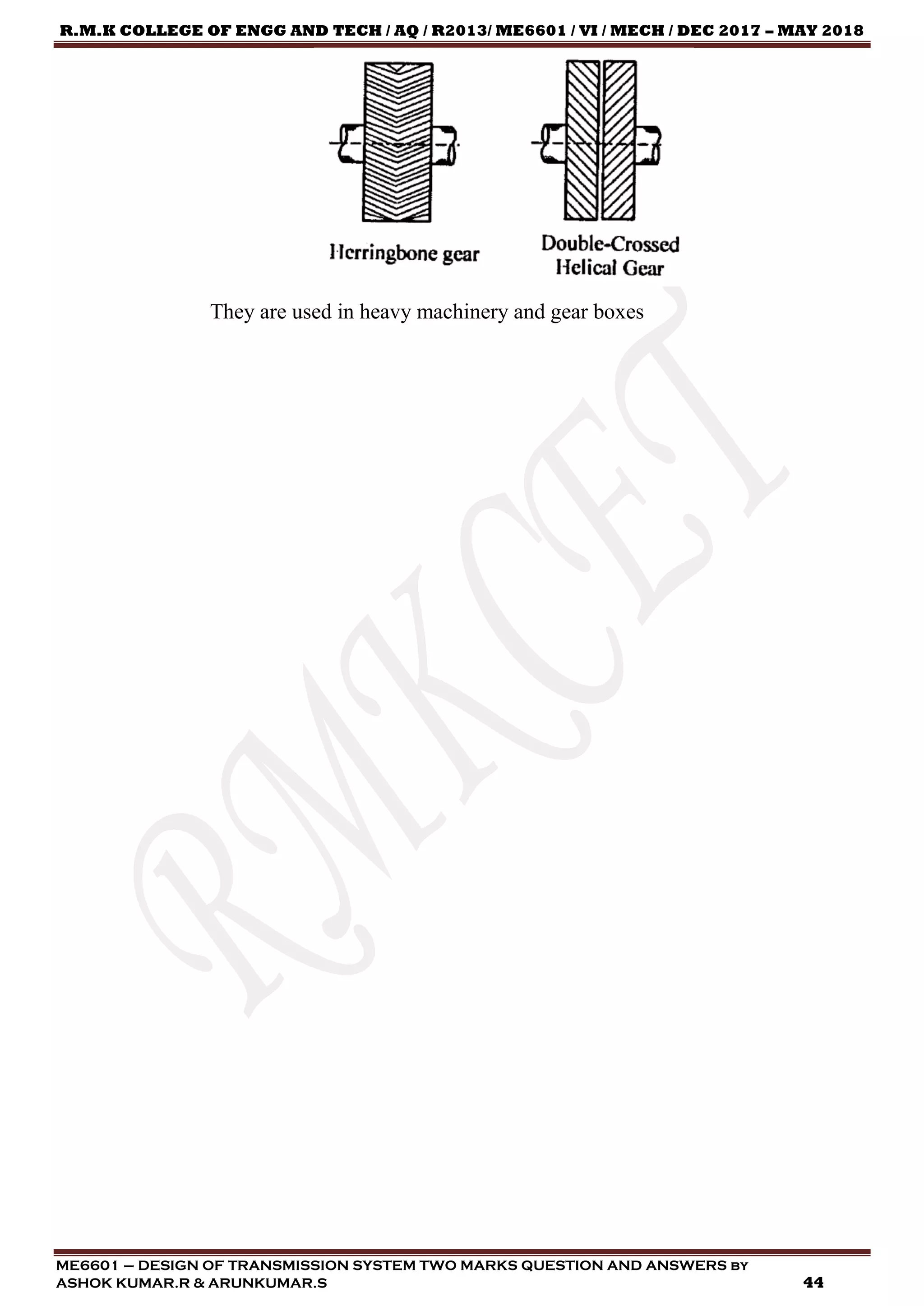
They are used in heavy machinery and gear boxes
2.64) What is herringbone gear? State its application.
[AU, Nov / Dec –2005, Apr / May – 2008]
A herringbone gear is a specific type of double helical gear. It is a side by
side combination of two helical gears of opposite hands, without any groove in
between. This balances the induced axial thrust.](https://image.slidesharecdn.com/twomarksqusestionandanswersme6601dtsdec2018-190304141415/75/ME6601-DESIGN-OF-TRANSMISSION-SYSTEMS-TWO-MARK-QUESTION-ANSWERS-43-2048.jpg)
![R.M.K COLLEGE OF ENGG AND TECH / AQ / R2013/ ME6601 / VI / MECH / DEC 2017 – MAY 2018
ME6601 – DESIGN OF TRANSMISSION SYSTEM TWO MARKS QUESTION AND ANSWERS by
ASHOK KUMAR.R & ARUNKUMAR.S 45
UNIT – III – BEVEL, WORM AND CROSS HELICAL GEARS
PART – A
3.1) What is bevel gear?
Bevel gear is the type of gear for which the teeth are cut on conical surface
in contrast with spur and helical gears for which the teeth are cut on cylindrical
surfaces. The structure of bevel gear is similar to an uniformly serrated frustum of a
cone.
3.2) How bevel gears are manufactured? [AU, Apr / May – 2016]
In manufacture of bevel gears, first the blanks are performed by casting or
forging followed by machining to desired dimensions in lathes or special purpose
machine. Then the teeth are produced in the blank by machining.
Straight toothed bevel gear:
By forming using milling cutter -low productivity and quality.
By generation- high accuracy and finish.
Spiral and hypoid bevel gears:
By generation-the cutter resembles face milling cutter.
3.3) When do we use bevel gears?
[AU, May / Jun – 2007, Apr / May – 2008, 2009, 2018]
If power and motion are to be transmitted between two intersecting shafts
then, bevel gears are used. Bevel gears are used in differential drives. Bevel gears
are used as the main mechanism for a hand drill. Spiral bevel gears are important
components on rotorcraft drive systems.](https://image.slidesharecdn.com/twomarksqusestionandanswersme6601dtsdec2018-190304141415/75/ME6601-DESIGN-OF-TRANSMISSION-SYSTEMS-TWO-MARK-QUESTION-ANSWERS-45-2048.jpg)
![R.M.K COLLEGE OF ENGG AND TECH / AQ / R2013/ ME6601 / VI / MECH / DEC 2017 – MAY 2018
ME6601 – DESIGN OF TRANSMISSION SYSTEM TWO MARKS QUESTION AND ANSWERS by
ASHOK KUMAR.R & ARUNKUMAR.S 46
3.4) When bevel gears are used? [AU, May / Jun – 2007]
If power and motion are to be transmitted between two intersecting shafts
then, bevel gears are used. Bevel gears are used in differential drives. Bevel gears
are used as the main mechanism for a hand drill. Spiral bevel gears are important
components on rotorcraft drive systems.
3.5) When bevel gear is preferred? [AU, May / Jun – 2009, Nov / Dec –2012]
If power and motion are to be transmitted between two intersecting shafts
then, bevel gears are used. Bevel gears are used in differential drives. Bevel gears
are used as the main mechanism for a hand drill. Spiral bevel gears are important
components on rotorcraft drive systems.
3.6) Under what situation, bevel gears are used? [AU, Apr / May – 2011]
If power and motion are to be transmitted between two intersecting shafts
then, bevel gears are used. Bevel gears are used in differential drives. Bevel gears
are used as the main mechanism for a hand drill. Spiral bevel gears are important
components on rotorcraft drive systems.
3.7) Define back cone radius for a bevel gear. [AU, Nov / Dec – 2016]
Cone distance (or) Back cone radius (or) pitch cone radius (R) in a bevel
gear is the distance along an element of the back cone from its apex to the pitch
cone.
3.8) What is a crown gear? [AU, May / Jun – 2011, Nov / Dec – 2016]
A crown gear is type of bevel gear whose shaft are right angle to each other
and the pitch angle of pinion is not equal to pitch angle of gear. The pitch cone
angle is 90 degrees.
𝜙 = 𝛿1 + 𝛿2 = 90°
𝛿1 ≠ 𝛿2
3.9) What is the specific feature of a miter gear? [AU, Nov / Dec –2004]
Miter gear is the special type of crown gear in which the shaft angle is 90
degree and the pitch angle of pinion and gear are equal. The pitch angle is 45
degree.
𝜙 = 𝛿1 + 𝛿2 = 90°
𝛿1 = 𝛿2 = 45°](https://image.slidesharecdn.com/twomarksqusestionandanswersme6601dtsdec2018-190304141415/75/ME6601-DESIGN-OF-TRANSMISSION-SYSTEMS-TWO-MARK-QUESTION-ANSWERS-46-2048.jpg)
![R.M.K COLLEGE OF ENGG AND TECH / AQ / R2013/ ME6601 / VI / MECH / DEC 2017 – MAY 2018
ME6601 – DESIGN OF TRANSMISSION SYSTEM TWO MARKS QUESTION AND ANSWERS by
ASHOK KUMAR.R & ARUNKUMAR.S 47
3.10) State whether true or false and justify. Mitre gears are used for connecting
non - intersecting shafts. [AU, Nov / Dec –2005]
False. Mitre gears are used for connecting intersecting shafts.
3.11) What is meant by Mitre gears? [AU, Nov / Dec – 2017]
Miter gear is the special type of crown gear in which the shaft angle is 90
degree and the pitch angle of pinion and gear are equal. The pitch angle is 45
degree.
𝜙 = 𝛿1 + 𝛿2 = 90°
𝛿1 = 𝛿2 = 45°
3.12) What is virtual number of teeth in bevel gears?
[AU, Apr / May – 2004, May / Jun – 2014, Nov / Dec –2014]
It is also called as Formative (or) Equivalent number of teeth. The number
of teeth in an equivalent spur gear in a plane normal to the tooth of bevel gear at
the larger end is known as virtual number of teeth.
𝑉𝑖𝑟𝑡𝑢𝑎𝑙 𝑁𝑢𝑚𝑏𝑒𝑟 𝑜𝑓 𝑡𝑒𝑒𝑡ℎ 𝑍 𝑣 =
𝑍
𝑐𝑜𝑠𝛿
Z = Actual number of teeth in the bevel gear
δ = Reference angle of the bevel gear.
3.13) Define the following terms.(a) pitch angle (b) shaft angle (c) cone distance
(d) face angle [AU, Apr / May – 2005, May / Jun – 2014]
Pitch Angle is the half of the cone angle subtended by a bevel gear at its
apex.
Shaft angle is the sum of the pitch angles of pinion and gear of a bevel
gear pair.
𝜙 = 𝛿1 + 𝛿2 = 90°
𝜙 = 𝑆ℎ𝑎𝑓𝑡 𝐴𝑛𝑔𝑙𝑒
𝛿1 = 𝑃𝑖𝑡𝑐ℎ 𝐴𝑛𝑔𝑙𝑒 𝑜𝑓 𝑃𝑖𝑛𝑖𝑜𝑛
𝛿2 = 𝑃𝑖𝑡𝑐ℎ 𝐴𝑛𝑔𝑙𝑒 𝑜𝑓 𝐺𝑒𝑎𝑟
Cone Distance (or) Back cone radius (or) pitch cone radius (R) in a bevel
gear is the distance along an element of the back cone from its apex to the pitch
cone.
Face angle is the angle subtended by the face of a tooth at the cone centre.](https://image.slidesharecdn.com/twomarksqusestionandanswersme6601dtsdec2018-190304141415/75/ME6601-DESIGN-OF-TRANSMISSION-SYSTEMS-TWO-MARK-QUESTION-ANSWERS-47-2048.jpg)
![R.M.K COLLEGE OF ENGG AND TECH / AQ / R2013/ ME6601 / VI / MECH / DEC 2017 – MAY 2018
ME6601 – DESIGN OF TRANSMISSION SYSTEM TWO MARKS QUESTION AND ANSWERS by
ASHOK KUMAR.R & ARUNKUMAR.S 48
Face angle= Pitch angle + Addendum angle
3.14) What is known as formative number of teeth on bevel gears?
[AU, Apr / May – 2017]
It is also called as Formative (or) Equivalent number of teeth. The number
of teeth in an equivalent spur gear in a plane normal to the tooth of bevel gear at
the larger end is known as virtual number of teeth.
𝑉𝑖𝑟𝑡𝑢𝑎𝑙 𝑁𝑢𝑚𝑏𝑒𝑟 𝑜𝑓 𝑡𝑒𝑒𝑡ℎ 𝑍 𝑣 =
𝑍
𝑐𝑜𝑠𝛿
Z = Actual number of teeth in the bevel gear
δ = Reference angle of the bevel gear.
3.15) What are the various forces acting on a bevel gear?
[AU, Nov / Dec –2009, May / Jun – 2013]
The force components acting on a bevel gear are:
Tangential force, Ft
Radial force, Fr
Axial force, Fa
3.16) List the forces acting on bevel gears. [AU, Nov / Dec – 2018]
The force components acting on a bevel gear are:
Tangential force, Ft
Radial force, Fr
Axial force, Fa
3.17) What is a Zerol bevel gears? [AU, Apr / May – 2015, Nov / Dec – 2018]
Zerol bevel gear is also a spiral bevel gear in which, the spiral angle is zero
at the middle of the face width.
3.18) What is the difference between an angular gear and a miter gear?
[AU, Nov / Dec –2012, 2013, 2015]
Miter gear is the special type of crown gear in which the shaft angle is 90
degree and the pitch angle of pinion and gear are equal. The pitch angle is 45
degree.
𝜙 = 𝛿1 + 𝛿2 = 90°
𝛿1 = 𝛿2 = 45°](https://image.slidesharecdn.com/twomarksqusestionandanswersme6601dtsdec2018-190304141415/75/ME6601-DESIGN-OF-TRANSMISSION-SYSTEMS-TWO-MARK-QUESTION-ANSWERS-48-2048.jpg)
![R.M.K COLLEGE OF ENGG AND TECH / AQ / R2013/ ME6601 / VI / MECH / DEC 2017 – MAY 2018
ME6601 – DESIGN OF TRANSMISSION SYSTEM TWO MARKS QUESTION AND ANSWERS by
ASHOK KUMAR.R & ARUNKUMAR.S 49
In some bevel-gear drives, the angles between the shafts may not be 90°,
but either more or less than 90°. These gears are called ‘Angular bevel gears’.
3.19) Specify the features of skew bevel gears. [AU, May / Jun – 2012]
Spiral gears are used to transmit power and motion between
nonintersecting and non-parallel axes. They are also called as crossed helical gear
(or) screw (or) skew gears.
3.20) Differentiate a straight bevel gear and a spiral bevel gear.
[AU, Apr / May – 2016]
STRAIGHT TEETH BEVEL GEAR SPIRAL TEETH BEVEL GEAR
In case of straight teeth bevel gear,
elements of the teeth are in the
form of a straight line, which
converges on a common apex.
Here contact between teeth of two
meshing gears occurs suddenly.
Due to sudden engagement, teeth
are subjected to impact loading.
Sudden engagement of teeth also
causes vibration and noise.
Load carrying capacity of straight
teeth bevel gear is comparatively
low
These are suitable for low to
moderate speed applications.
Life of the straight teeth bevel gear
is shorter as it is subjected to
impact loading and vibration.
In case of spiral teeth bevel gear,
elements of the teeth are in the form
of a spiral curve, which also
converges on a common apex.
Here contact between teeth of two
meshing gears occurs gradually.
Due to gradual engagement, teeth
are subjected to gradual loading.
Operation of spiral teeth bevel gear
is smooth and quite.
Load carrying capacity of spiral
teeth bevel gear is high
These can be utilized at high speed
applications also.
Spiral teeth bevel gears have longer
life.
3.21) Mention two characteristics of hypoid gear. [AU, Apr / May – 2010]
These gears are similar to spiral bevel but the pitch surfaces are
hyperbolic and not conical.](https://image.slidesharecdn.com/twomarksqusestionandanswersme6601dtsdec2018-190304141415/75/ME6601-DESIGN-OF-TRANSMISSION-SYSTEMS-TWO-MARK-QUESTION-ANSWERS-49-2048.jpg)
![R.M.K COLLEGE OF ENGG AND TECH / AQ / R2013/ ME6601 / VI / MECH / DEC 2017 – MAY 2018
ME6601 – DESIGN OF TRANSMISSION SYSTEM TWO MARKS QUESTION AND ANSWERS by
ASHOK KUMAR.R & ARUNKUMAR.S 50
Pinion can be offset above, or below the gear centre, thus allowing
larger pinion diameter.
The operation is quiet and smoother.
They have high reduction ratio and longer life.
3.22) Write down the relation between the axial force and tangential force
component. [AU, Nov / Dec –2010]
𝐹𝑎 = 𝐹𝑡 ∗ 𝑡𝑎𝑛𝛼 + 𝑠𝑖𝑛𝛿1
Fa = Axial Force
Ft = Tangential Force
α = Pressure Angle
δ1 = Reference angle of pinion
3.23) What is Lewis (tooth) form factor? [AU, Apr / May – 2010]
The form factor, Y, is a function of the number of teeth, pressure angle,
and involute depth of the gear. It accounts for the geometry of the tooth, but does
not include stress concentration.
3.24) What is reference angle? How is it related to speed ratio of bevel gear ratio?
[AU, May / Jun – 2012]
Pitch cone angle or Reference angle (δ2) is the angle that the pitch line
makes with the gear axis.
𝑖 = 𝑡𝑎𝑛 𝛿2
𝛿2 = 𝑃𝑖𝑡𝑐ℎ 𝐴𝑛𝑔𝑙𝑒 (𝑜𝑟) 𝑅𝑒𝑓𝑒𝑟𝑒𝑛𝑐𝑒 𝐴𝑛𝑔𝑙𝑒 𝑜𝑓 𝐺𝑒𝑎𝑟
3.25) What kind of contact occurs between worm and wheel? How does it differ
from other gears? [AU, Nov / Dec –2015]
In worm gear drive, sliding contact is occurred between the worm and
wheel whereas other gears such as spur, helical and bevel gears transmit power by
rolling contact.
3.26) What are the commonly used materials for worm and wheel?
[AU, May / Jun – 2007]
Worm materials: Carbon steels and alloy steels
Worm wheel materials: Cast iron and phosphor bronze.](https://image.slidesharecdn.com/twomarksqusestionandanswersme6601dtsdec2018-190304141415/75/ME6601-DESIGN-OF-TRANSMISSION-SYSTEMS-TWO-MARK-QUESTION-ANSWERS-50-2048.jpg)
![R.M.K COLLEGE OF ENGG AND TECH / AQ / R2013/ ME6601 / VI / MECH / DEC 2017 – MAY 2018
ME6601 – DESIGN OF TRANSMISSION SYSTEM TWO MARKS QUESTION AND ANSWERS by
ASHOK KUMAR.R & ARUNKUMAR.S 51
3.27) Why phosphor bronze is widely used for worm gears?
[AU, Nov / Dec –2013]
The phosphor bronze is widely used for worm gears in order to resist and
reduce wear of the worms. The wear will be excessive with cast iron or steel.
3.28) When do we use worm gears? [AU, May / Jun – 2013]
Worm gears are constructed of a worm and a gear (sometimes referred to
as a worm wheel), with non-parallel, non-intersecting shafts oriented 90 degrees to
each other.
Worm drives are used in presses, rolling mills, conveying engineering,
mining industry machines, on rudders, and worm drive saws. In addition, milling
heads and rotary tables are positioned using high-precision duplex worm drives
with adjustable backlash. Worm gears are used on many lift/elevator and escalator-
drive applications due to their compact size and the non-reversibility of the gear.
3.29) Under what circumstances, the worm gears are used for power
transmission? [AU, Nov / Dec – 2017]
They are used in most of the stringed instruments.
In conventional steering mechanisms, worm and worm wheels are
used.
Used in lifts/ elevators because of their compactness and self-locking
characteristic.
Chain pulley block.
3.30) Give some applications of worm - gear drive. [AU, May / Jun – 2007]
They are used in most of the stringed instruments.
In conventional steering mechanisms, worm and worm wheels are
used.
Used in lifts/ elevators because of their compactness and self-locking
characteristic.
Chain pulley block.
3.31) Write some applications of worm-gear drive.
[AU, May / Jun – 2011, Nov / Dec – 2016]
They are used in most of the stringed instruments.](https://image.slidesharecdn.com/twomarksqusestionandanswersme6601dtsdec2018-190304141415/75/ME6601-DESIGN-OF-TRANSMISSION-SYSTEMS-TWO-MARK-QUESTION-ANSWERS-51-2048.jpg)
![R.M.K COLLEGE OF ENGG AND TECH / AQ / R2013/ ME6601 / VI / MECH / DEC 2017 – MAY 2018
ME6601 – DESIGN OF TRANSMISSION SYSTEM TWO MARKS QUESTION AND ANSWERS by
ASHOK KUMAR.R & ARUNKUMAR.S 52
In conventional steering mechanisms, worm and worm wheels are
used.
Used in lifts/ elevators because of their compactness and self-locking
characteristic.
Chain pulley block.
3.32) In worm gear drive, only the wheel is designed. Why?
[AU, Apr / May – 2011]
In a worm gear drive, the worm is stronger than the wheel.
Hence, only the wheel has to be designed which is the weaker part.
3.33) Mention the reason for irreversibility in worm gears. [AU, Nov / Dec –2010]
A worm and worm wheel drive is said to be self-locking or irreversibility
if the coefficient of friction is greater than the tangent of the lead angle.
𝝁 > 𝒕𝒂𝒏 𝜸
3.34) What is irreversibility in worm gear? [AU, Nov / Dec – 2018]
A worm and worm wheel drive is said to be self-locking or irreversibility
if the coefficient of friction is greater than the tangent of the lead angle.
𝝁 > 𝒕𝒂𝒏 𝜸
3.35) Write the conditions of self-locking of worm gears in terms of lead and
Pressure angles. [AU, Apr / May – 2017]
A worm and worm wheel drive is said to be self-locking if the coefficient
of friction is greater than the product of cosine of pressure angle and tangent of the
lead angle.
𝜇 ≥ 𝑐𝑜𝑠𝛼 ∗ 𝑡𝑎𝑛𝛾
3.36) What are the various forces acting on worm and worm gears?
Tangential force
Axial or thrust force
Radial or separating force
3.37) What is helical angle of worm? [AU, Apr / May – 2016]
Helix angle, β in a worm is the angle between a tangent to the thread at the
pitch diameter and the axis of the worm. The helix angle is preferably 6°
maximum.](https://image.slidesharecdn.com/twomarksqusestionandanswersme6601dtsdec2018-190304141415/75/ME6601-DESIGN-OF-TRANSMISSION-SYSTEMS-TWO-MARK-QUESTION-ANSWERS-52-2048.jpg)
![R.M.K COLLEGE OF ENGG AND TECH / AQ / R2013/ ME6601 / VI / MECH / DEC 2017 – MAY 2018
ME6601 – DESIGN OF TRANSMISSION SYSTEM TWO MARKS QUESTION AND ANSWERS by
ASHOK KUMAR.R & ARUNKUMAR.S 53
3.38) Give the speed ratio range of worm – wheel drive. [AU, May / Jun – 2012]
The speed ratio that can be obtained in a worm wheel drive can be up to
300:1.
3.39) Usually worm is made of hard materials and worm gear is made of softer
material – Justify. [AU, Nov / Dec –2009]
In general, worm is made of hard metal while the worm gear is made from
relatively soft metal.
The reasons are:
Worm is subjected to more number of stress cycles than the worm
wheel
The number of teeth on the worm gear is relatively high compared to
worm with its number of starts being usually 1 to 4.
By reducing the worm gear hardness, the friction, contact stress and
hence the wear on the worm teeth is reduced.
Also, the plastic flow and cold working of the soft material will tend
to correct the errors in the tooth action that arise due to the
misalignment.
3.40) Why is dynamic loading rarely considered in worm gear drives?
[AU, Nov / Dec –2011]
The dynamic load in a worm gear drive is not so severe because of its
sliding action between the worm and worm wheel. Hence, the dynamic loading is
usually not considered in worm gear drives.
3.41) In which gear – drive is self – locking available?
[AU, Nov / Dec –2008, Apr / May – 2015, 2018]
Self-locking mechanism is available in a worm and worm gear drive.
3.42) What is a 'Self-locking condition' in worm and worm wheel?
In general;
The worm is the driver and worm wheel is the driven members.
The power and motion can be transmitted only from the worm to the
worm wheel.
The reverse motion is not possible.
This condition is known as self-locking of worm and worm wheel.](https://image.slidesharecdn.com/twomarksqusestionandanswersme6601dtsdec2018-190304141415/75/ME6601-DESIGN-OF-TRANSMISSION-SYSTEMS-TWO-MARK-QUESTION-ANSWERS-53-2048.jpg)
![R.M.K COLLEGE OF ENGG AND TECH / AQ / R2013/ ME6601 / VI / MECH / DEC 2017 – MAY 2018
ME6601 – DESIGN OF TRANSMISSION SYSTEM TWO MARKS QUESTION AND ANSWERS by
ASHOK KUMAR.R & ARUNKUMAR.S 54
A worm and worm wheel drive is said to be self-locking if the
coefficient of friction is greater than the tangent of the lead angle.
𝝁 > 𝒕𝒂𝒏 𝜸
3.43) Why is a multistart worm more efficient than a single start one?
[AU, Nov / Dec – 2005]
If the coefficient of friction and diameter factor, ‘q’ are constant. The
efficiency of a worm drive is inversely proportional to the speed ratio. The
efficiency is directly proportional to the lead angle ‘γ’.
𝐺𝑒𝑎𝑟 𝑅𝑎𝑡𝑖𝑜 (𝑜𝑟) 𝑆𝑝𝑒𝑒𝑑 𝑅𝑎𝑡𝑖𝑜 𝑖 =
𝑁𝑜 𝑜𝑓 𝑡𝑒𝑒𝑡ℎ 𝑜𝑛 𝑡ℎ𝑒 𝑤ℎ𝑒𝑒𝑙
𝑁𝑜 𝑜𝑓 𝑠𝑡𝑎𝑟𝑡𝑠
𝐿𝑒𝑎𝑑 𝐴𝑛𝑔𝑙𝑒 𝛾 = 𝑡𝑎𝑛−1
[
𝑁𝑜 𝑜𝑓 𝑠𝑡𝑎𝑟𝑡𝑠
𝐷𝑖𝑎𝑚𝑒𝑡𝑒𝑟 𝑓𝑎𝑐𝑡𝑜𝑟
]
Multi start worm has less speed ratio and high lead angle. Hence, they have
high efficiency.
3.44) When the number of start of a worm is increased in a worm gear drive, how
it affects the other parameters and action of the drive? [AU, Apr / May – 2004]
𝐺𝑒𝑎𝑟 𝑅𝑎𝑡𝑖𝑜 (𝑜𝑟) 𝑆𝑝𝑒𝑒𝑑 𝑅𝑎𝑡𝑖𝑜 𝑖 =
𝑁𝑜 𝑜𝑓 𝑡𝑒𝑒𝑡ℎ 𝑜𝑛 𝑡ℎ𝑒 𝑤ℎ𝑒𝑒𝑙
𝑁𝑜 𝑜𝑓 𝑠𝑡𝑎𝑟𝑡𝑠
𝐿𝑒𝑎𝑑 𝐴𝑛𝑔𝑙𝑒 𝛾 = 𝑡𝑎𝑛−1
[
𝑁𝑜 𝑜𝑓 𝑠𝑡𝑎𝑟𝑡𝑠
𝐷𝑖𝑎𝑚𝑒𝑡𝑒𝑟 𝑓𝑎𝑐𝑡𝑜𝑟
]
The increasing the number of starts reduces the speed ratio and increases
the lead angle. If the coefficient of friction and diameter factor, ‘q’ are constant.
The efficiency of a worm drive is inversely proportional to the speed ratio. The
efficiency is directly proportional to the lead angle ‘γ’. Hence, the efficiency
increases.
3.45) Write the advantages of worm gear drive. [AU, May / Jun – 2008]
The advantages of a worm gear drive are:
Worm gear drives operate silently and smoothly.
They are self-locking. Reverse movement will be restricted.
They occupy less space.
They have good meshing effectiveness.
They can be used for reducing speed and increasing torque.](https://image.slidesharecdn.com/twomarksqusestionandanswersme6601dtsdec2018-190304141415/75/ME6601-DESIGN-OF-TRANSMISSION-SYSTEMS-TWO-MARK-QUESTION-ANSWERS-54-2048.jpg)
![R.M.K COLLEGE OF ENGG AND TECH / AQ / R2013/ ME6601 / VI / MECH / DEC 2017 – MAY 2018
ME6601 – DESIGN OF TRANSMISSION SYSTEM TWO MARKS QUESTION AND ANSWERS by
ASHOK KUMAR.R & ARUNKUMAR.S 55
High velocity ratio of the order of 300 can be obtained in a single
step.
3.46) Mention the advantages of worm gear drive. [AU, Nov / Dec –2014]
The advantages of a worm gear drive are:
Worm gear drives operate silently and smoothly.
They are self-locking. Reverse movement will be restricted.
They occupy less space.
They have good meshing effectiveness.
They can be used for reducing speed and increasing torque.
High velocity ratio of the order of 300 can be obtained in a single
step.
3.47) What are the disadvantages of worm gear drive? [AU, Nov / Dec – 2017]
The disadvantages of a worm gear drive are:
Low efficiency
Low power transmission
More heat will be produced and hence this drive can be operated
inside an oil reservoir or extra cooling fan is required in order to
dissipate the heat from the drive
3.48) State the advantage of worm gear drive in weight lifting machines.
[AU, Apr / May – 2008]
The self-locking feature acts as a secondary brake and prevents
damage to the load and the system.
The lowering speed can be regulated easily and the load will not be
allowed to free fall.
The drive does not require complicated controls (or) high
maintenance mechanism to ensure safe lifts.
3.49) What are the main types of failure in worm gear drives?
[AU, May / Jun – 2012, Nov / Dec –2012]
Pitting:
Pitting is a form of surface fatigue and may be of three types:
Initial (corrective)
Destructive](https://image.slidesharecdn.com/twomarksqusestionandanswersme6601dtsdec2018-190304141415/75/ME6601-DESIGN-OF-TRANSMISSION-SYSTEMS-TWO-MARK-QUESTION-ANSWERS-55-2048.jpg)
![R.M.K COLLEGE OF ENGG AND TECH / AQ / R2013/ ME6601 / VI / MECH / DEC 2017 – MAY 2018
ME6601 – DESIGN OF TRANSMISSION SYSTEM TWO MARKS QUESTION AND ANSWERS by
ASHOK KUMAR.R & ARUNKUMAR.S 56
Normal
Tooth fracture:
Such failures are rare and are indicative of overloading.
Tooth breakage may be the result of high overloads of either
impact or static in nature.
Ridging:
Ridging is caused by wear or plastic flow of surface and
subsurface material due to high contact compressive stresses
and low sliding velocities.
3.50) What are the two types of failure in worm gear drives?
[AU, Nov / Dec – 2016]
Pitting:
Pitting is a form of surface fatigue and may be of three types:
Initial (corrective)
Destructive
Normal
Tooth fracture:
Such failures are rare and are indicative of overloading.
Tooth breakage may be the result of high overloads of either
impact or static in nature.
Ridging:
Ridging is caused by wear or plastic flow of surface and
subsurface material due to high contact compressive stresses
and low sliding velocities.
3.51) Define normal pitch of a worm gear. [AU, Apr / May – 2016]
Normal pitch, pn in a worm is the distance measured from a point in one
thread to the corresponding point on the adjacent thread, along a normal to the
thread of the worm.
3.52) A pair of worm gears is designated as 2 / 54 / 10 / 5. Find the gear ratio.
[AU, Nov / Dec –2010]
A standard worm gear pair is designated as zw / zg / q / m / a.
zw = number of starts on worm,](https://image.slidesharecdn.com/twomarksqusestionandanswersme6601dtsdec2018-190304141415/75/ME6601-DESIGN-OF-TRANSMISSION-SYSTEMS-TWO-MARK-QUESTION-ANSWERS-56-2048.jpg)
![R.M.K COLLEGE OF ENGG AND TECH / AQ / R2013/ ME6601 / VI / MECH / DEC 2017 – MAY 2018
ME6601 – DESIGN OF TRANSMISSION SYSTEM TWO MARKS QUESTION AND ANSWERS by
ASHOK KUMAR.R & ARUNKUMAR.S 57
zg = number of teeth on worm gear,
q = diametral quotient,
m = module
a = centre distance.
A pair of worm gears is designated as 2 / 54 / 10 / 5
zw = number of starts on worm = 2
zg = number of teeth on worm gear = 54
q = diametral quotient = 10
m = module = 5
𝑖 =
𝑧2
𝑧1
=
𝑧 𝑔
𝑧 𝑤
=
54
2
= 27
3.53) Why is the efficiency of a worm gear drive comparatively low?
[AU, Apr / May – 2004, Nov / Dec –2007]
They have a smaller gear-tooth lead (helix) angle, which causes more
surface contact between the teeth.
This sliding action causes higher friction which results in heat
generation and power loss.
The "churning" of lubricating oil also reduces the efficiency.
("Churning" is the undesirable friction that occurs between fluids due
to continued agitation of the lubricant. Over lubrication is the main
cause for this.)
3.54) How do you specify a worm gear pair?
A standard worm gear pair is designated as zw / zg / q / m / a.
zw = number of starts on worm,
zg = number of teeth on worm gear,
q = diametral quotient,
m = module
a = centre distance.
3.55) When do we employ crossed helical gear? [AU, Apr / May – 2010]
A pair of crossed helical gears, also known as spiral gears, are used to
connect and transmit motion between two non-parallel and non-interesting shafts.](https://image.slidesharecdn.com/twomarksqusestionandanswersme6601dtsdec2018-190304141415/75/ME6601-DESIGN-OF-TRANSMISSION-SYSTEMS-TWO-MARK-QUESTION-ANSWERS-57-2048.jpg)
![R.M.K COLLEGE OF ENGG AND TECH / AQ / R2013/ ME6601 / VI / MECH / DEC 2017 – MAY 2018
ME6601 – DESIGN OF TRANSMISSION SYSTEM TWO MARKS QUESTION AND ANSWERS by
ASHOK KUMAR.R & ARUNKUMAR.S 58
The contact between the mating teeth is always a point, these gears are suitable for
low power transmission applications only.
3.56) Why is the crossed helical gear drive not used for power transmission?
[AU, Nov / Dec –2007]
While meshing, the teeth have only point contact. Hence, the contact stress
is very high which results in rapid wear. Therefore, they have a very low load
carrying capacity and not recommended for high power transmission.
3.57) Calculate the angle between the shafts of a crossed helical gears made of two
right handed helical gears of 15º helix angle each. [AU, May / Jun – 2009]
𝑆ℎ𝑎𝑓𝑡 𝐴𝑛𝑔𝑙𝑒 𝛾 = 𝛽1 + 𝛽2
(“+” is used since both gears are of the same hand)
𝐻𝑒𝑙𝑖𝑥 𝐴𝑛𝑔𝑙𝑒 = 𝛽1 = 𝛽2 = 15°
𝑆ℎ𝑎𝑓𝑡 𝐴𝑛𝑔𝑙𝑒 𝛾 = 𝛽1 + 𝛽2 = 15 + 15 = 30°
3.58) Calculate the angle between the shafts of a crossed helical gears made of two
left handed helical gears of 10º helix angle each. [AU, Nov / Dec –2012]
𝑆ℎ𝑎𝑓𝑡 𝐴𝑛𝑔𝑙𝑒 𝛾 = 𝛽1 + 𝛽2
(“+” is used since both gears are of the same hand)
𝐻𝑒𝑙𝑖𝑥 𝐴𝑛𝑔𝑙𝑒 = 𝛽1 = 𝛽2 = 10°
𝑆ℎ𝑎𝑓𝑡 𝐴𝑛𝑔𝑙𝑒 𝛾 = 𝛽1 + 𝛽2 = 15 + 15 = 20°](https://image.slidesharecdn.com/twomarksqusestionandanswersme6601dtsdec2018-190304141415/75/ME6601-DESIGN-OF-TRANSMISSION-SYSTEMS-TWO-MARK-QUESTION-ANSWERS-58-2048.jpg)
![R.M.K COLLEGE OF ENGG AND TECH / AQ / R2013/ ME6601 / VI / MECH / DEC 2017 – MAY 2018
ME6601 – DESIGN OF TRANSMISSION SYSTEM TWO MARKS QUESTION AND ANSWERS by
ASHOK KUMAR.R & ARUNKUMAR.S 59
UNIT – IV – GEAR BOXES
PART – A
4.1) What is a gear box?
The gearbox that uses gears and gear trains to provide speed and torque
conversions from a rotating power source to another device.
4.2) What purpose does the housing of a gear - box serve?
Gear box housing or casing is use as container inside which, the gears,
shafts, bearings and other components are mounted. It also prevents the entry of
dust inside the housing and reduce noise of operation. The housing safe guard the
inner components
4.3) What is the function of spacers in a gear - box?
[AU, Nov / Dec –2004, 2008, Apr / May – 2005, May / Jun – 2011]
Spacers are sleeve like components which are mounted on shafts between
gears and bearings or one gear to another gear in order to maintain the distance
between them and avoid interruption between them.
4.4) For what purpose are gear - box used? [AU, Apr / May – 2018]
Gearboxes are used to increase torque while reducing the speed of a prime
mover output shaft (e.g. a motor crankshaft). This means that the output shaft of a
gearbox rotates at a slower rate than the input shaft, and this reduction in speed
produces a mechanical advantage, increasing torque.
4.5) Specify four types of gearboxes. [AU, Nov / Dec –2014]
Constant Mesh Gearbox
Sliding Mesh Gearbox
Synchromesh Gearbox
Epicyclic Gearbox.
4.6) What is a speed diagram? [AU, Apr / May – 2018]
Speed diagram or structural diagram is the graphical representation of
different speed of output shaft, motor shaft and intermediate shafts.
4.7) What is multispeed gear box? [AU, Apr / May – 2016]
A gearbox that gives multi output speeds is called a multispeed gearbox. A
multispeed gearbox converts a single high speed input into a number of speed](https://image.slidesharecdn.com/twomarksqusestionandanswersme6601dtsdec2018-190304141415/75/ME6601-DESIGN-OF-TRANSMISSION-SYSTEMS-TWO-MARK-QUESTION-ANSWERS-59-2048.jpg)
![R.M.K COLLEGE OF ENGG AND TECH / AQ / R2013/ ME6601 / VI / MECH / DEC 2017 – MAY 2018
ME6601 – DESIGN OF TRANSMISSION SYSTEM TWO MARKS QUESTION AND ANSWERS by
ASHOK KUMAR.R & ARUNKUMAR.S 60
outputs in many stages. It has more than two gears and equivalent number of
shafts.
4.8) Name the series in which speeds of multi - speed gear box are arranged.
[AU, May / Jun – 2007, 2011]
The series, R5, R10, R20, R40 & R80; R20 and R40 are widely used in
multispeed gearboxes. These series follow geometric progression.
4.9) What is R20 series? [AU, Apr / May – 2016]
R20 refers to Renard preferred numbers series 20. It has a total of 20
members in the series. Leaving 1.00; First number is equal to the step ratio 𝜙 =
( √10
20
)
1
= 10(1
20⁄ )
= 1.16. Each member will be multiplied by the step ratio to
get the next number in the geometric series. The last number will be 10.00
4.10) What are preferred numbers?
[AU, Apr / May – 2011, 2016, Nov / Dec –2012, 2014, May / Jun – 2013]
Preferred numbers are the conveniently rounded off values derived from
geometric series, including the integral powers of 10 and having as common ratios
the following factors: √10
5
; √10
10
; √10
20
; √10
40
𝑎𝑛𝑑 √10
80
These ratios are called
as the Step Ratios, ϕ and approximately equal to 1.58, 1.26, 1.12, 1.06 and 1.03
respectively.
4.11) What are the main components of a gear - box?
Gears for getting different speeds
Shafts for mounting gears
Bearings for supporting shafts
Spacers to maintain the distance between gears.
Levers for changing the position of gear engagement
Gear box housing for covering all the inner components
Oil seals for lubrication
4.12) What is a speed reducers?
A speed reducer (or) transmission box (or) commonly known as gearbox is
a gear mechanism used to reduce the angular speed of the output shaft when
compared with that of the input shaft. They are used to obtain different speeds with
varying torques. If the speed is low, the torque will be high and vice versa.](https://image.slidesharecdn.com/twomarksqusestionandanswersme6601dtsdec2018-190304141415/75/ME6601-DESIGN-OF-TRANSMISSION-SYSTEMS-TWO-MARK-QUESTION-ANSWERS-60-2048.jpg)
![R.M.K COLLEGE OF ENGG AND TECH / AQ / R2013/ ME6601 / VI / MECH / DEC 2017 – MAY 2018
ME6601 – DESIGN OF TRANSMISSION SYSTEM TWO MARKS QUESTION AND ANSWERS by
ASHOK KUMAR.R & ARUNKUMAR.S 61
4.13) Name the types of speed reducers
Single reduction speed reducers
Multi reduction speed reducers
The single reduction speed reducer is one set of gear drive such as pinion
and one gear (wheel) can be operated. In multi reduction speed reducers two or
more set of gears are employed.
4.14) Classify speed reducers. [AU, Nov / Dec –2012]
Single reduction speed reducers
Multi reduction speed reducers
4.15) What are the methods of lubrication in speed reducers?
[AU, Nov / Dec –2004, 2011]
The methods of lubrication in speed reducers (gearboxes) are:
Splash (spray) lubrication
Force-feed (pressure) lubrication.
4.16) What does the ray - diagram of a gear - box indicate?[AU, May / Jun – 2012]
Ray diagram (or) speed diagram is a graphical representation of the
structural formula used in the gear box design. It provides the number of stages
(shafts) in the system, the transmission ratio at each stage and the different speeds
at each stage. The last stage gives the total number of final speeds with their
corresponding values.
4.17) What is meant by ray diagrams? [AU, Apr / May – 2010, May / Jun – 2012]
Ray diagram (or) speed diagram is a graphical representation of the
structural formula used in the gear box design. It provides the number of stages
(shafts) in the system, the transmission ratio at each stage and the different speeds
at each stage. The last stage gives the total number of final speeds with their
corresponding values.
4.18) Write the significance of structural formula. [AU, Nov / Dec –2015]
Structural formula is the formula that gives the method of obtaining the
required number of output speeds in a gearbox. It is used to obtain the number of
stages (shafts) and required number of gears to obtain the desired range and steps
of output speeds in a gear box design.](https://image.slidesharecdn.com/twomarksqusestionandanswersme6601dtsdec2018-190304141415/75/ME6601-DESIGN-OF-TRANSMISSION-SYSTEMS-TWO-MARK-QUESTION-ANSWERS-61-2048.jpg)
![R.M.K COLLEGE OF ENGG AND TECH / AQ / R2013/ ME6601 / VI / MECH / DEC 2017 – MAY 2018
ME6601 – DESIGN OF TRANSMISSION SYSTEM TWO MARKS QUESTION AND ANSWERS by
ASHOK KUMAR.R & ARUNKUMAR.S 62
4.19) Differentiate ray diagram and structural diagram.
[AU, Nov / Dec –2007, 2016]
Ray diagram (or) speed diagram is a graphical representation of the
structural formula used in the gear box design. It provides the number of stages
(shafts) in the system, the transmission ratio at each stage and the different speeds
at each stage. The last stage gives the total number of final speeds with their
corresponding values.
Structural diagram (or) Kinematic layout is a pictorial representation of
the gearbox describing the arrangement of gears. It also provides the number of
stages (shafts), the pair of gears that will mesh and their arrangement.
4.20) Distinguish between structural diagram and speed diagram.
[AU, Nov / Dec –2011]
Ray diagram (or) speed diagram is a graphical representation of the
structural formula used in the gear box design. It provides the number of stages
(shafts) in the system, the transmission ratio at each stage and the different speeds
at each stage. The last stage gives the total number of final speeds with their
corresponding values.
Structural diagram (or) Kinematic layout is a pictorial representation of
the gearbox describing the arrangement of gears. It also provides the number of
stages (shafts), the pair of gears that will mesh and their arrangement.
4.21) What is step ratio? [AU, May / Jun – 2007, Nov / Dec –2013, 2016]
Step ratio (or) Progression ratio, ϕ is the ratio between the maximum
speed to the minimum speed among the two adjacent speeds in a transmission. In
other words, it is the ratio between one speed to the previous lower speed.
𝜙 𝑛−1
=
𝑁 𝑚𝑎𝑥
𝑁 𝑚𝑖𝑛
4.22) What is step ratio in gear box? [AU, May / Jun – 2012]
Step ratio (or) Progression ratio, ϕ is the ratio between the maximum
speed to the minimum speed among the two adjacent speeds in a transmission. In
other words, it is the ratio between one speed to the previous lower speed.
𝜙 𝑛−1
=
𝑁 𝑚𝑎𝑥
𝑁 𝑚𝑖𝑛](https://image.slidesharecdn.com/twomarksqusestionandanswersme6601dtsdec2018-190304141415/75/ME6601-DESIGN-OF-TRANSMISSION-SYSTEMS-TWO-MARK-QUESTION-ANSWERS-62-2048.jpg)
![R.M.K COLLEGE OF ENGG AND TECH / AQ / R2013/ ME6601 / VI / MECH / DEC 2017 – MAY 2018
ME6601 – DESIGN OF TRANSMISSION SYSTEM TWO MARKS QUESTION AND ANSWERS by
ASHOK KUMAR.R & ARUNKUMAR.S 63
4.23) What is step ratio? Name the series in which speeds of multi-speed gear box
are arranged. [AU, May / Jun – 2014]
Step ratio (or) Progression ratio, ϕ is the ratio between the maximum
speed to the minimum speed among the two adjacent speeds in a transmission. In
other words, it is the ratio between one speed to the previous lower speed.
𝜙 𝑛−1
=
𝑁 𝑚𝑎𝑥
𝑁 𝑚𝑖𝑛
The series, R5, R10, R20, R40 & R80; R20 and R40 are widely used in
multispeed gearboxes. These series follow geometric progression.
4.24) What is geometric progression? [AU, Apr / May – 2010]
In order to get a series of output speeds from a gearbox, geometric
progression is used. By using geometric progression the speed is reduced uniformly
in different stages. Geometric progression, also known as a geometric sequence, is
a sequence of numbers where each term after the first is found by multiplying the
previous one by a fixed, non-zero number called the common ratio (called as
progression ratio or step ratio in gear box design).
4.25) Explain the ray diagram and list the advantages of geometric progression.
[AU, Apr / May – 2004]
Ray diagram (or) speed diagram is a graphical representation of the
structural formula used in the gear box design. It provides the number of stages
(shafts) in the system, the transmission ratio at each stage and the different speeds
at each stage. The last stage gives the total number of final speeds with their
corresponding values.
Advantages of geometric progression:
Minimum speed loss
Less number of gears can be employed
More even range of output speeds at each stage
Compact layout
Preferred numbers can be employed effectively.](https://image.slidesharecdn.com/twomarksqusestionandanswersme6601dtsdec2018-190304141415/75/ME6601-DESIGN-OF-TRANSMISSION-SYSTEMS-TWO-MARK-QUESTION-ANSWERS-63-2048.jpg)
![R.M.K COLLEGE OF ENGG AND TECH / AQ / R2013/ ME6601 / VI / MECH / DEC 2017 – MAY 2018
ME6601 – DESIGN OF TRANSMISSION SYSTEM TWO MARKS QUESTION AND ANSWERS by
ASHOK KUMAR.R & ARUNKUMAR.S 64
4.26) What is the purpose of the ray diagram in designing the gearbox?
[AU, Nov / Dec – 2017]
Ray diagram (or) speed diagram is a graphical representation of the
structural formula used in the gear box design. It provides the number of stages
(shafts) in the system, the transmission ratio at each stage and the different speeds
at each stage. The last stage gives the total number of final speeds with their
corresponding values.
4.27) Why geometric progression is selected for arranging the speeds in gear
boxes? [AU, Apr / May – 2017]
Geometric progression is selected due to the following advantages
Minimum speed loss
Less number of gears can be employed
More even range of output speeds at each stage
Compact layout
Preferred numbers can be employed effectively.
4.28) Define progression ratio. [AU, Nov / Dec –2015, 2018]
Step ratio (or) Progression ratio, ϕ is the ratio between the maximum
speed to the minimum speed among the two adjacent speeds in a transmission. In
other words, it is the ratio between one speed to the previous lower speed.
𝜙 𝑛−1
=
𝑁 𝑚𝑎𝑥
𝑁 𝑚𝑖𝑛
4.29) What is a 'Lay shaft' in a gearbox?
It is an intermediate shaft within a gearbox that carries gears, but does not
transfer the primary drive of the gearbox either in or out of the gearbox.
4.30) List any two methods used for changing speeds in gear boxes.
[AU, Nov / Dec – 2016]
In a constant-mesh manual gearbox: The speeds are changed by small
clutches that connect the various gear sets to their shafts so that power is
transmitted through them.
In a sliding mesh gearbox: The gears in the main shaft are moved using
selector fork that makes a perfect mesh with the required gear in the lay shaft. This
gives the required speed ratios.](https://image.slidesharecdn.com/twomarksqusestionandanswersme6601dtsdec2018-190304141415/75/ME6601-DESIGN-OF-TRANSMISSION-SYSTEMS-TWO-MARK-QUESTION-ANSWERS-64-2048.jpg)
![R.M.K COLLEGE OF ENGG AND TECH / AQ / R2013/ ME6601 / VI / MECH / DEC 2017 – MAY 2018
ME6601 – DESIGN OF TRANSMISSION SYSTEM TWO MARKS QUESTION AND ANSWERS by
ASHOK KUMAR.R & ARUNKUMAR.S 65
In a synchromesh gearbox: The parts which ultimately are to be engaged
are first brought into frictional contact with a synchronizer unit. This equalizes
their speed, after which these may be engaged smoothly to obtain the required
output speed.
4.31) List the ways by which the number of intermediate steps may be arranged
in a gear box. [AU, Apr / May – 2010]
The structural formula depends on the required number of stages (shafts)
and required number of gears to obtain the desired range and steps of output speeds
in a gear box design. For the same number of stages, the same set of output speeds
could be obtained in many ways by changing the number of gears in the
intermediate steps.
4.32) What is the use of a 'Synchronizer' in a synchromesh gearbox?
Synchronizer is a device used in a synchromesh gearbox that avoids the
necessity of double declutching. The gears which ultimately are to be engaged are
first brought into frictional contact with synchronizer which equalizes their speed,
after which these may be engaged smoothly.
4.33) What are the possible arrangements to achieve 12 speeds from a gear box?
[AU, Apr / May – 2011, May / Jun – 2013, Nov / Dec – 2016]
3 (1) ∗ 2(3) ∗ 2(6)
2 (1) ∗ 3(2) ∗ 2(6)
2 (1) ∗ 2(2) ∗ 3(4)
4.34) What are the possible arrangements to achieve 16 speeds from a gear box?
[AU, Nov / Dec –2010, 2018]
3 (1) ∗ 3(3) ∗ 2(7)
3 (1) ∗ 2(3) ∗ 3(4)
2 (1) ∗ 3(2) ∗ 3(4)
4.35) Sketch the kinematic layout of gears for 3 speeds between two shafts.
[AU, Apr / May – 2008, May / Jun – 2014]](https://image.slidesharecdn.com/twomarksqusestionandanswersme6601dtsdec2018-190304141415/75/ME6601-DESIGN-OF-TRANSMISSION-SYSTEMS-TWO-MARK-QUESTION-ANSWERS-65-2048.jpg)
![R.M.K COLLEGE OF ENGG AND TECH / AQ / R2013/ ME6601 / VI / MECH / DEC 2017 – MAY 2018
ME6601 – DESIGN OF TRANSMISSION SYSTEM TWO MARKS QUESTION AND ANSWERS by
ASHOK KUMAR.R & ARUNKUMAR.S 66
4.36) List six standard speeds starting from 18 rpm with a step ratio 1.4.
[AU, Apr / May – 2008]
Step ratio, ϕ = 1.4.
1.06 * 1.06 * 1.06 * 1.06 * 1.06 * 1.06 = 1.418
PSG Page 7 .20, R40 series:
First speed: 1.8; standard speed 18 rpm
Second speed: after 1.8 is 2.50; standard speed 25 rpm.
Third speed: after 2.5 is 3.55; standard speed 35.5 rpm.
Fourth speed: after 3.55 is 5.00; standard speed 50 rpm.
Fifth speed: after 5.0 is 7.10; standard speed 71 rpm.
Sixth speed: after 7.1 is 10.00; standard speed 100 rpm.
4.37) Calculate standard step ratio for six speed gear with speed ranging between
100 and 560 rpm. [AU, Nov / Dec –2012]
𝜙 𝑛−1
=
𝑁 𝑚𝑎𝑥
𝑁 𝑚𝑖𝑛
𝜙6−1
=
560
100
𝜙 = 1.411
𝜙 = 1.06 ∗ 1.06 ∗ 1.06 ∗ 1.06 ∗ 1.06 ∗ 1.06
R40 series is selected](https://image.slidesharecdn.com/twomarksqusestionandanswersme6601dtsdec2018-190304141415/75/ME6601-DESIGN-OF-TRANSMISSION-SYSTEMS-TWO-MARK-QUESTION-ANSWERS-66-2048.jpg)
![R.M.K COLLEGE OF ENGG AND TECH / AQ / R2013/ ME6601 / VI / MECH / DEC 2017 – MAY 2018
ME6601 – DESIGN OF TRANSMISSION SYSTEM TWO MARKS QUESTION AND ANSWERS by
ASHOK KUMAR.R & ARUNKUMAR.S 67
4.38) What does the ray diagram of gear box indicates?
[AU, Nov / Dec –2010, May / Jun – 2011, Apr / May – 2017]
Ray diagram (or) speed diagram is a graphical representation of the
structural formula used in the gear box design. It provides the number of stages
(shafts) in the system, the transmission ratio at each stage and the different speeds
at each stage. The last stage gives the total number of final speeds with their
corresponding values.
4.39) What is an overlapping gearbox? Give an example.
If in a gearbox, any of the output speeds could be obtained by two different
sets of gears then the gearbox is known as an overlapping gearboxes. In such cases,
the required number of speeds <maximum possible number of speeds.
For example:
For obtaining 14 speeds, the combination has to be: 2 * 3 * 3 = 18 (or)
3 * 3 * 2 = 18 (or) 3 * 2 * 3 = 18.
(18-14) = 4 speeds are the overlapping speeds and they could be obtained by two
different sets of gears.
4.40) Draw the ray diagram for a six speed gear box
[AU, May / Jun – 2006, 2007, Apr / May – 2015, Nov / Dec – 2018]](https://image.slidesharecdn.com/twomarksqusestionandanswersme6601dtsdec2018-190304141415/75/ME6601-DESIGN-OF-TRANSMISSION-SYSTEMS-TWO-MARK-QUESTION-ANSWERS-67-2048.jpg)
![R.M.K COLLEGE OF ENGG AND TECH / AQ / R2013/ ME6601 / VI / MECH / DEC 2017 – MAY 2018
ME6601 – DESIGN OF TRANSMISSION SYSTEM TWO MARKS QUESTION AND ANSWERS by
ASHOK KUMAR.R & ARUNKUMAR.S 68
4.41) Draw the ray diagram for 12 speed gear box. [AU, Nov / Dec – 2017]
4.42) Which type of gear is used in constant mesh gear box? Justify
[AU, Nov / Dec –2009]
Helical gears are used in constant mesh gearbox. The gears are in constant
mesh and need not be moved in a constant mesh gearbox. Hence, we can use
helical gears which ensure smooth and quiet operation.
4.43) What are the points to be considered while designing a sliding mesh type of
multi – speed gear box? [AU, Apr / May – 2010]
It is preferable to have the transmission ratio ‘i’ such that
1
4
≤ 𝑖 ≤ 2
This means, at any single stage, the speed ratio,
𝑁 𝑚𝑎𝑥
𝑁 𝑚𝑖𝑛
≤ 8
At each stage, the two conditions to be satisfied are:
𝑁 𝑚𝑖𝑛
𝑁𝑖𝑛𝑝𝑢𝑡
≥
1
4
𝑁 𝑚𝑎𝑥
𝑁 𝑖𝑛𝑝𝑢𝑡
≤ 2
Except in the first stage, in all other stages;
𝑁 𝑚𝑖𝑛 ≤ 𝑁𝑖𝑛𝑝𝑢𝑡 ≤ 𝑁 𝑚𝑎𝑥
4.44) Give some applications of constant mesh gear box. [AU, May / Jun – 2007]
Gearboxes used in automobiles.
Machine tools like lathe, drilling machine](https://image.slidesharecdn.com/twomarksqusestionandanswersme6601dtsdec2018-190304141415/75/ME6601-DESIGN-OF-TRANSMISSION-SYSTEMS-TWO-MARK-QUESTION-ANSWERS-68-2048.jpg)
![R.M.K COLLEGE OF ENGG AND TECH / AQ / R2013/ ME6601 / VI / MECH / DEC 2017 – MAY 2018
ME6601 – DESIGN OF TRANSMISSION SYSTEM TWO MARKS QUESTION AND ANSWERS by
ASHOK KUMAR.R & ARUNKUMAR.S 69
Rolling mills and,
Chemical processing machinery.
4.45) Compare sliding mesh and synchromesh gear box. [AU, Nov / Dec –2009]
Sliding mesh gear box: The meshing of the gears takes place by sliding of
gears on each other. With sliding mesh gear box, double de-clutching is necessary
to bring the two sets of dog teeth to the same speed so that they can be slid into
engagement quietly.
Synchromesh gear box: Synchromesh is a type of constant mesh gearbox.
The only difference between these two is that in the constant mesh gearbox the
gears are locked with the shaft with the help of dog clutch but in synchromesh
gearbox they are connected by a device called synchronizer.
4.46) State the advantages of the constant mesh gearbox over the sliding mesh
gear box.
Hassle free shifting, no long pressing the clutch
Takes less time in shifting
More compact design, can be cased in a compact housing
Reduced wear of the gears
Helical gears can be used instead of spur gears
Overall life of gearbox elements increases because of using helical
gears
Efficiency of a constant mesh is more because of helical gears
Noise and vibrations are also reduced because of smooth constant
meshing
Size of the clutch used is also small, in case of constant mesh
No jerks are felt while shifting as gears are always in mesh and are
simply and smoothly (dog and cone clutch) locked to transmit
power.
4.47) Give any two applications of multi speed gearbox. [AU, Nov / Dec – 2017]
They are used wherever multiple spindle speeds are required. Example
Automobile
Gearboxes used in machine tools like: lathe, drilling machines where
multiple spindle speeds are required.](https://image.slidesharecdn.com/twomarksqusestionandanswersme6601dtsdec2018-190304141415/75/ME6601-DESIGN-OF-TRANSMISSION-SYSTEMS-TWO-MARK-QUESTION-ANSWERS-69-2048.jpg)
![R.M.K COLLEGE OF ENGG AND TECH / AQ / R2013/ ME6601 / VI / MECH / DEC 2017 – MAY 2018
ME6601 – DESIGN OF TRANSMISSION SYSTEM TWO MARKS QUESTION AND ANSWERS by
ASHOK KUMAR.R & ARUNKUMAR.S 70
4.48) List out the basic rules to be followed for optimum gear box design.
[AU, Nov / Dec –2007, May / Jun – 2011]
It is preferable to have the transmission ratio ‘i’ such that
1
4
≤ 𝑖 ≤ 2
This means, at any single stage, the speed ratio,
𝑁 𝑚𝑎𝑥
𝑁 𝑚𝑖𝑛
≤ 8
At each stage, the two conditions to be satisfied are:
𝑁 𝑚𝑖𝑛
𝑁𝑖𝑛𝑝𝑢𝑡
≥
1
4
𝑁 𝑚𝑎𝑥
𝑁 𝑖𝑛𝑝𝑢𝑡
≤ 2
Except in the first stage, in all other stages;
𝑁 𝑚𝑖𝑛 ≤ 𝑁𝑖𝑛𝑝𝑢𝑡 ≤ 𝑁 𝑚𝑎𝑥
4.49) State any three basic rules to be followed while designing a gear box.
[AU, Nov / Dec –2013]
It is preferable to have the transmission ratio ‘i’ such that
1
4
≤ 𝑖 ≤ 2
This means, at any single stage, the speed ratio,
𝑁 𝑚𝑎𝑥
𝑁 𝑚𝑖𝑛
≤ 8
At each stage, the two conditions to be satisfied are:
𝑁 𝑚𝑖𝑛
𝑁𝑖𝑛𝑝𝑢𝑡
≥
1
4
𝑁 𝑚𝑎𝑥
𝑁 𝑖𝑛𝑝𝑢𝑡
≤ 2
Except in the first stage, in all other stages;
𝑁 𝑚𝑖𝑛 ≤ 𝑁𝑖𝑛𝑝𝑢𝑡 ≤ 𝑁 𝑚𝑎𝑥
4.50) State any two basic rules to be followed while designing a gear box.
[AU, Apr / May – 2016]
It is preferable to have the transmission ratio ‘i’ such that
1
4
≤ 𝑖 ≤ 2
This means, at any single stage, the speed ratio,
𝑁 𝑚𝑎𝑥
𝑁 𝑚𝑖𝑛
≤ 8
At each stage, the two conditions to be satisfied are:
𝑁 𝑚𝑖𝑛
𝑁𝑖𝑛𝑝𝑢𝑡
≥
1
4](https://image.slidesharecdn.com/twomarksqusestionandanswersme6601dtsdec2018-190304141415/75/ME6601-DESIGN-OF-TRANSMISSION-SYSTEMS-TWO-MARK-QUESTION-ANSWERS-70-2048.jpg)
![R.M.K COLLEGE OF ENGG AND TECH / AQ / R2013/ ME6601 / VI / MECH / DEC 2017 – MAY 2018
ME6601 – DESIGN OF TRANSMISSION SYSTEM TWO MARKS QUESTION AND ANSWERS by
ASHOK KUMAR.R & ARUNKUMAR.S 71
𝑁 𝑚𝑎𝑥
𝑁 𝑖𝑛𝑝𝑢𝑡
≤ 2
Except in the first stage, in all other stages;
𝑁 𝑚𝑖𝑛 ≤ 𝑁𝑖𝑛𝑝𝑢𝑡 ≤ 𝑁 𝑚𝑎𝑥
4.51) Write any two principles to be followed to obtain optimum design in gear
box. [AU, Nov / Dec – 2017]
It is preferable to have the transmission ratio ‘i’ such that
1
4
≤ 𝑖 ≤ 2
This means, at any single stage, the speed ratio,
𝑁 𝑚𝑎𝑥
𝑁 𝑚𝑖𝑛
≤ 8
At each stage, the two conditions to be satisfied are:
𝑁 𝑚𝑖𝑛
𝑁𝑖𝑛𝑝𝑢𝑡
≥
1
4
𝑁 𝑚𝑎𝑥
𝑁 𝑖𝑛𝑝𝑢𝑡
≤ 2
Except in the first stage, in all other stages;
𝑁 𝑚𝑖𝑛 ≤ 𝑁𝑖𝑛𝑝𝑢𝑡 ≤ 𝑁 𝑚𝑎𝑥
4.52) Where are multi-speed gear boxes employed? [AU, May / Jun – 2009]
They are used wherever multiple spindle speeds are required. Example
Automobile
Gearboxes used in machine tools like: lathe, drilling machines where
multiple spindle speeds are required.
4.53) Name the series in which speeds are arranged in multi-speed gear boxes.
[AU, May / Jun – 2009]
The series, R5, R10, R20, R40 & R80; R20 and R40 are widely used in
multispeed gearboxes. These series follow geometric progression.
4.54) What are the conditions required for interchangeability in toothed gears?
[AU, Nov / Dec – 2015]
The conditions to be satisfied for interchangeability of all gears are:
The gears in mesh must have the same circular pitch, diametral
module, diametral pitch, pressure angle, addendum and dedendum.
The tooth thickness must be one half of the circular pitch.
4.55) What is a fluid coupling? What is its use?](https://image.slidesharecdn.com/twomarksqusestionandanswersme6601dtsdec2018-190304141415/75/ME6601-DESIGN-OF-TRANSMISSION-SYSTEMS-TWO-MARK-QUESTION-ANSWERS-71-2048.jpg)

![R.M.K COLLEGE OF ENGG AND TECH / AQ / R2013/ ME6601 / VI / MECH / DEC 2017 – MAY 2018
ME6601 – DESIGN OF TRANSMISSION SYSTEM TWO MARKS QUESTION AND ANSWERS by
ASHOK KUMAR.R & ARUNKUMAR.S 74
UNIT – V – CAMS, CLUTCHES AND BRAKES
PART – A
5.1) What is a cam?
Cam is a machine member, which resembles egg shaped disc and is used
for transmitting rotary motion to reciprocating motion through another member
called as follower. In a cam drive, cam acts as a driver and the follower acts as
driven member.
5.2) What are the factors to be considered for the design of cam drives?
Follower motion
Profile of the cam
Amount of force applied
Displacement, velocity and acceleration
Material of cam and follower
Environmental conditions
5.3) How are cams classified?
Based on the shape of cam
Flat or wedge cam
Disc cam
Cylindrical cam
Based on follower motion
Dwell – rise – dwell cam
Dwell – rise – return – dwell cam
Rise – return – rise cam
5.4) What are the functions of Cam? [AU, Nov / Dec – 2017]
The main functions of cam is for transmitting rotary motion to
reciprocating motion through another member called as follower.
5.5) Mention a few applications of cams. [AU, Nov / Dec – 2016]
Cam and follower mechanisms find their place in many machines and
mechanisms and the following are a few examples:
Internal Combustion (I C) Engines (to actuate the inlet and outlet
valves).
Textile Machinery](https://image.slidesharecdn.com/twomarksqusestionandanswersme6601dtsdec2018-190304141415/75/ME6601-DESIGN-OF-TRANSMISSION-SYSTEMS-TWO-MARK-QUESTION-ANSWERS-74-2048.jpg)
![R.M.K COLLEGE OF ENGG AND TECH / AQ / R2013/ ME6601 / VI / MECH / DEC 2017 – MAY 2018
ME6601 – DESIGN OF TRANSMISSION SYSTEM TWO MARKS QUESTION AND ANSWERS by
ASHOK KUMAR.R & ARUNKUMAR.S 75
Machine Tools like Lathe, Shaping Machine, Planar Machine, Slotting
Machine (in feed mechanisms)
Paper Cutting Machines
Printing Machines
Clocks.
5.6) Define the base circle and pitch circle with respect to cam.
[AU, Nov / Dec –2010]
Base Circle: It is the smallest circle, drawn tangential to cam profile. The
base circle decides the overall size of the cam and thus is fundamental feature.
Pitch Point: Pitch point corresponds to the point of maximum pressure
angle, and a circle drawn with its centre at the cam centre, to pass through the pitch
point, is known as the pitch circle.
5.7) Define pitch point in cam. [AU, Nov / Dec –2013]
Pitch point corresponds to the point of maximum pressure angle, and a
circle drawn with its centre at the cam centre, to pass through the pitch point, is
known as the pitch circle.
5.8) Name four profiles normally used in cams. [AU, May / Jun – 2009]
The important cam profiles are:
Straight line (or) Uniform velocity
Simple harmonic motion
Cycloidal
Parabolic (or) Constant acceleration
5.9) Define Jerk. [AU, Nov / Dec – 2016]
Cycloid cam profile gives no jerk. It is the third Derivative of follower
motion and denoted as;
𝐽𝑒𝑟𝑘 = 𝑗 =
𝑑3
𝑦
𝑑𝑡3
Where, “y” is the follower displacement.
5.10) Name the profile of cam that gives no jerk.
[AU, May / Jun – 2007, Nov / Dec –2015]
Cycloid cam profile gives no jerk.](https://image.slidesharecdn.com/twomarksqusestionandanswersme6601dtsdec2018-190304141415/75/ME6601-DESIGN-OF-TRANSMISSION-SYSTEMS-TWO-MARK-QUESTION-ANSWERS-75-2048.jpg)
![R.M.K COLLEGE OF ENGG AND TECH / AQ / R2013/ ME6601 / VI / MECH / DEC 2017 – MAY 2018
ME6601 – DESIGN OF TRANSMISSION SYSTEM TWO MARKS QUESTION AND ANSWERS by
ASHOK KUMAR.R & ARUNKUMAR.S 76
5.11) What is the significance of pressure angle in cam design?
[AU, Nov / Dec –2007, Apr / May – 2016]
Pressure angle is the angle between the direction of the follower movement
and the normal to the pitch curve. In the design of the cam profile, the pressure
angle is important. If the pressure angle is large then the reciprocating follower can
jam its bearing.
5.12) State the advantage of cam. [AU, Apr / May – 2008]
Very long life
Quiet Operations
Low shock and acceleration
High load carrying capacity.
5.13) How can pressure angle be reduced in cam design? [AU, May / Jun – 2012]
Pressure Angle: It is the measure of steepness of the cam profile. The angle
between the direction of the follower movement and the normal to the pitch curve
at any point is called pressure angle. The pressure angle can be reduced by
increasing the cam size or by adjusting the offset.
5.14) Mention the types of followers based on the shape, used in cam drives?
The popular followers used in cam mechanisms are:
Knife-edge follower
Roller follower
Flat faced (plate) follower
Mushroom (spherical) follower.
5.15) Why a roller follower is preferable over a knife-edge follower?
Knife-edge follower is subjected to excessive wear due to sliding motion
and pointed tip. Roller follower has rolling contact resulting in less wear and hence,
preferable.
5.16) What is undercutting in cams?
The cam profile must be a smooth, continuous curve without any loop. If
the curvature of the pitch curve is too sharp, then the part of the cam shape will be
lost and therefore the required cam motion cannot be achieved. Also, under cutting
results in too high surface stresses. Such a cam is said to be undercut.](https://image.slidesharecdn.com/twomarksqusestionandanswersme6601dtsdec2018-190304141415/75/ME6601-DESIGN-OF-TRANSMISSION-SYSTEMS-TWO-MARK-QUESTION-ANSWERS-76-2048.jpg)
![R.M.K COLLEGE OF ENGG AND TECH / AQ / R2013/ ME6601 / VI / MECH / DEC 2017 – MAY 2018
ME6601 – DESIGN OF TRANSMISSION SYSTEM TWO MARKS QUESTION AND ANSWERS by
ASHOK KUMAR.R & ARUNKUMAR.S 77
5.17) How the undercutting can be prevented?
The undercutting can be prevented by:
Decreasing the follower lift
Increasing the cam rotation angle
Increasing the cam size (base circle)
Keeping the minimum radius of curvature of a cam as large as
possible.
5.18) What is a clutch?
Clutch is a machine component which acts as a temporary coupling and it
is mainly used in automobiles for engaging and disengaging the driving shaft to the
driven shaft
5.19) Specify the types of clutches.
Positive clutches
Friction clutches
Disc clutches
Cone clutches
Centrifugal clutches
Magnetic clutches
5.20) What is the function of clutch in a transmission system?
[AU, Apr / May – 2016]
Clutches are mechanical devices used in the power transmission systems
which require frequent starting and stopping of power supply from one shaft to
another. The force of friction is used for engaging and disengaging the driving
shaft to the driven shaft.
5.21) Name different types of clutch. [AU, Nov / Dec –2012]
Positive clutches
Friction clutches
Disc clutches
Cone clutches
Centrifugal clutches
Magnetic clutches](https://image.slidesharecdn.com/twomarksqusestionandanswersme6601dtsdec2018-190304141415/75/ME6601-DESIGN-OF-TRANSMISSION-SYSTEMS-TWO-MARK-QUESTION-ANSWERS-77-2048.jpg)
![R.M.K COLLEGE OF ENGG AND TECH / AQ / R2013/ ME6601 / VI / MECH / DEC 2017 – MAY 2018
ME6601 – DESIGN OF TRANSMISSION SYSTEM TWO MARKS QUESTION AND ANSWERS by
ASHOK KUMAR.R & ARUNKUMAR.S 78
5.22) How is the uniform rate of wear assumption valid for clutches?
[AU, Apr / May – 2008]
In clutches, the value of normal pressure, axial load for the given clutch is
limited by the rate of wear that can be tolerated in the linings. Moreover the
assumptions in uniform wear rate gives lower calculated clutch capacity that the
assumptions of uniform pressure. Hence clutches are usually designed on the basis
of uniform wear.
5.23) Differentiate between uniform pressure and uniform wear theories adopted
in the design of clutches. [AU, Nov / Dec –2014]
Uniform-pressure theory:
In uniform-pressure theory, it is assumed that the pressure is
uniform throughout the friction surfaces.
It is applicable only when the friction lining is new.
Uniform wear theory:
This theory assumes that the wear is uniform throughout.
When the friction lining is used over a period of time, wear occurs.
Hence, in the design of clutches, the uniform wear theory is used.
5.24) What is meant by positive clutch? [AU, Nov / Dec –2015]
A clutch which transmits power from the driving shaft to the driven shaft
by means of positive contact like interlocking of claws, teeth is called a positive
clutch. In positive clutches, the slip is negligible and the angular velocity of output
shaft nearly equals that of the input speed. Due to positive contact, minimum
friction and hence negligible heat generation. They can transmit relatively high
torque. However, they cannot be engaged at higher speeds.
5.25) Why positive clutch used?
In positive clutches, the slip is negligible and the angular velocity of output
shaft nearly equals that of the input speed. Due to positive contact, minimum
friction and hence negligible heat generation. They can transmit relatively high
torque.
5.26) Classify clutches based on the coupling methods.
[AU, Nov / Dec –2004, May / Jun – 2014]
Based on the method of coupling, the clutches are classified as:](https://image.slidesharecdn.com/twomarksqusestionandanswersme6601dtsdec2018-190304141415/75/ME6601-DESIGN-OF-TRANSMISSION-SYSTEMS-TWO-MARK-QUESTION-ANSWERS-78-2048.jpg)
![R.M.K COLLEGE OF ENGG AND TECH / AQ / R2013/ ME6601 / VI / MECH / DEC 2017 – MAY 2018
ME6601 – DESIGN OF TRANSMISSION SYSTEM TWO MARKS QUESTION AND ANSWERS by
ASHOK KUMAR.R & ARUNKUMAR.S 79
Positive clutches- Positive contact
Frictional clutches - Frictional contact
Magnetic clutches- Electromagnetic force
Fluid coupling- Fluid contact.
5.27) Distinguish between wet and dry operation of clutches.
[AU, Nov / Dec –2012]
Dry operation:
When the clutch operates without any lubrication, it is said to
be operating under dry condition.
The coefficient of friction and torque transmitting capacity are
high.
Due to the absence of any medium, the rate of heat dissipation
is low.
Wet operation:
When the clutch operates with proper lubrication, it is said to be
operating under wet condition.
The coefficient of friction and torque transmitted are
comparatively low.
Due to the presence of the lubricant, considerable amount of
heat is dissipated from the clutch.
5.28) Write the difference between dry and wet clutch. [AU, Nov / Dec – 2017]
Dry clutch:
When the clutch operates without any lubrication, it is said to
be operating under dry condition.
The coefficient of friction and torque transmitting capacity are
high.
Due to the absence of any medium, the rate of heat dissipation
is low.
Wet clutch:
When the clutch operates with proper lubrication, it is said to be
operating under wet condition.](https://image.slidesharecdn.com/twomarksqusestionandanswersme6601dtsdec2018-190304141415/75/ME6601-DESIGN-OF-TRANSMISSION-SYSTEMS-TWO-MARK-QUESTION-ANSWERS-79-2048.jpg)
![R.M.K COLLEGE OF ENGG AND TECH / AQ / R2013/ ME6601 / VI / MECH / DEC 2017 – MAY 2018
ME6601 – DESIGN OF TRANSMISSION SYSTEM TWO MARKS QUESTION AND ANSWERS by
ASHOK KUMAR.R & ARUNKUMAR.S 80
The coefficient of friction and torque transmitted are
comparatively low.
Due to the presence of the lubricant, considerable amount of
heat is dissipated from the clutch.
5.29) What are the desirable properties of friction material to be used for
clutches? [AU, Nov / Dec –2005, 2008, Apr / May – 2010]
A few desirable characteristics of friction material are:
Good compressive strength
Higher friction coefficient, wear resistant
Light weight
Good thermal capacity and fast dissipation of heat generated
Low Cost.
5.30) Name few commonly used friction materials.
[AU, Apr / May – 2011, 2016, Nov / Dec – 2018]
There are a number of different materials that are used as friction materials
including steel, aluminium, cotton fabrics, polymers, vegetable fibres, fibre glass
and asbestos. Asbestos has been classified as unsafe and is generally not as
common in modern day clutches.
5.31) Name the different friction materials used in friction clutches.
[AU, May / Jun – 2007]
There are a number of different materials that are used as friction materials
including steel, aluminium, cotton fabrics, polymers, vegetable fibres, fibre glass
and asbestos. Asbestos has been classified as unsafe and is generally not as
common in modern day clutches.
5.32) Give examples for axial and radial friction clutches. [AU, Nov / Dec – 2016]
Axial clutches:
The clutching action takes place due to axial forces.
Example:
Plate Clutches
Single Plate (disc) Clutch
Multiple Plates (discs) Clutch
Cone Clutches](https://image.slidesharecdn.com/twomarksqusestionandanswersme6601dtsdec2018-190304141415/75/ME6601-DESIGN-OF-TRANSMISSION-SYSTEMS-TWO-MARK-QUESTION-ANSWERS-80-2048.jpg)
![R.M.K COLLEGE OF ENGG AND TECH / AQ / R2013/ ME6601 / VI / MECH / DEC 2017 – MAY 2018
ME6601 – DESIGN OF TRANSMISSION SYSTEM TWO MARKS QUESTION AND ANSWERS by
ASHOK KUMAR.R & ARUNKUMAR.S 81
Radial clutches:
The force acts radially to enforce clutching action.
Example:
Centrifugal Clutches.
Internal Expanding Drum (or) Rim Clutches.
5.33) What are the effects of temperature rise in clutches? [AU, Nov / Dec –2007]
High temperature in the friction surfaces may cause the plates to be
welded together.
This may cause deformation of plates and shafts.
Excess temperature results in thermal stresses which may cause cracks
in the metallic plates.
High temperature increases the wear rate.
This may also result in oxidation of the lubricant that reduces the effects
of lubrication.
The system may also fail ultimately.
5.34) What is the use of a clutch in power transmission system?
[AU, May / Jun – 2007]
Clutches are mechanical devices used in the power transmission systems
which require frequent starting and stopping of power supply from one shaft to
another. The force of friction is used for engaging and disengaging the driving
shaft to the driven shaft.
5.35) In what ways are clutches different from couplings?
Coupling:
Couplings are used to connect the input and output shafts
permanently.
Though they can be dismantled, the purpose of using a coupling is to
have a permanent joint during the operation.
Clutch:
Clutch also connects the input and output shafts, but temporarily.
When the clutch is applied, the output shaft gets disconnected from the
input shaft.](https://image.slidesharecdn.com/twomarksqusestionandanswersme6601dtsdec2018-190304141415/75/ME6601-DESIGN-OF-TRANSMISSION-SYSTEMS-TWO-MARK-QUESTION-ANSWERS-81-2048.jpg)
![R.M.K COLLEGE OF ENGG AND TECH / AQ / R2013/ ME6601 / VI / MECH / DEC 2017 – MAY 2018
ME6601 – DESIGN OF TRANSMISSION SYSTEM TWO MARKS QUESTION AND ANSWERS by
ASHOK KUMAR.R & ARUNKUMAR.S 82
During the remaining period, a clutch holds together the moving
members to transmit the power.
5.36) Sketch a cone clutch. [AU, May / Jun – 2007]
5.37) Under what condition of a clutch is uniform rate of wear assumption more
valid? [AU, May / Jun – 2009, 2011]
If the clutch is old and being used over a period of time, uniform rate of
wear theory is assumed.
5.38) Why is it necessary to dissipate the heat generated during clutch operation?
[AU, Nov / Dec –2009, May / Jun – 2012]
The heat generated affects the clutches. The effects of heat generated are:
High temperature in the friction surfaces may cause the plates to be
welded together.
This may cause deformation of plates and shafts.
Excess temperature results in thermal stresses which may cause
cracks in the metallic plates.
5.39) Why are cone clutches better than disc clutches?
For the same outer radius, cone clutches have relatively larger
friction area and wedging action.
Hence, they can transmit more power when compared to a plate
clutch for the same actuating force.
5.40) What is the axial force required at the engagement and disengagement of
cone clutch? [AU, May / Jun – 2013, Nov / Dec – 2018]
Axial Force required for engaging the Clutch,
𝑊𝑒 = 𝑊𝑛(𝜇 cos 𝛼 + sin 𝛼)
Axial Force required for disengaging the Clutch,](https://image.slidesharecdn.com/twomarksqusestionandanswersme6601dtsdec2018-190304141415/75/ME6601-DESIGN-OF-TRANSMISSION-SYSTEMS-TWO-MARK-QUESTION-ANSWERS-82-2048.jpg)
![R.M.K COLLEGE OF ENGG AND TECH / AQ / R2013/ ME6601 / VI / MECH / DEC 2017 – MAY 2018
ME6601 – DESIGN OF TRANSMISSION SYSTEM TWO MARKS QUESTION AND ANSWERS by
ASHOK KUMAR.R & ARUNKUMAR.S 83
𝑊𝑑 = 𝑊𝑛(𝜇 cos 𝛼 − sin 𝛼)
Wn – Normal Axial Force
μ – Coefficient of friction
α – Semi Cone angle
5.41) What is meant by friction clutches?
A friction clutch is a clutch in which the drive is transmitted by the friction
between surfaces attached to the driving and driven shafts. These surfaces are lined
with cork, asbestos, or other fibrous material.
5.42) What factors should be considered when designing friction clutches?
The friction materials for the clutch should have high coefficient of
friction and they should not be affected by moisture and oil
The design should be light weight and the engagement should be
smooth without shock and fast disengagement without drag
Provision should be made to transfer of heat from the clutch during
operation
5.43) What are the factors upon which the torque capacity of a clutch depends?
[AU, Nov / Dec –2011]
The factors that affect the torque transmitting capacity are:
Total number of pairs of friction surfaces
Coefficient of friction between the friction surfaces
Axial force exerted
Mean radius of the friction surfaces.
5.44) What are the materials used for lining of friction surfaces?
[AU, Apr / May – 2005]
In dry friction clutches, the friction plates are made of steel or cast iron on
a lining of some asbestos based friction materials.
In wet friction clutches the friction plates are made up of steels with
subsequent hardening with cermet as lining materials.
5.45) What are the desirable properties of friction material to be used for
clutches? [AU, Nov / Dec –2005]
A few desirable characteristics of friction material are:
Good compressive strength](https://image.slidesharecdn.com/twomarksqusestionandanswersme6601dtsdec2018-190304141415/75/ME6601-DESIGN-OF-TRANSMISSION-SYSTEMS-TWO-MARK-QUESTION-ANSWERS-83-2048.jpg)
![R.M.K COLLEGE OF ENGG AND TECH / AQ / R2013/ ME6601 / VI / MECH / DEC 2017 – MAY 2018
ME6601 – DESIGN OF TRANSMISSION SYSTEM TWO MARKS QUESTION AND ANSWERS by
ASHOK KUMAR.R & ARUNKUMAR.S 84
Higher friction coefficient, wear resistant
Light weight
Good thermal capacity and fast dissipation of heat generated
Low Cost.
5.46) How the ‘uniform rate of wear’ assumption is valid for clutches?
[AU, Apr / May – 2008]
In clutches the value of normal pressure, axial load for the given clutch is
limited by the rate of wear that can be tolerated in the brake linings. Moreover the
assumption of uniform wear rate gives a lower calculated clutch capacity that the
assumption of uniform pressure. Hence the clutches are usually designed on the
basis of uniform wear.
5.47) When do we use multiple disk clutches? [AU, Apr / May – 2010]
Multiple plate clutches are used when a large amount of power is to be
transmitted. The power/ torque transmitted gets multiplied by the number of
friction plates available.
5.48) If a multi disc clutch has 8 discs in the driving shaft, 9 discs in the driven
shaft, then how many number of contact surfaces will it have?
[AU, May / Jun – 2006]
𝑁𝑜 𝑜𝑓 𝑐𝑜𝑛𝑡𝑎𝑐𝑡 𝑠𝑢𝑟𝑓𝑎𝑐𝑒𝑠 = 𝑛1 + 𝑛2 − 1
𝑁𝑜 𝑜𝑓 𝑐𝑜𝑛𝑡𝑎𝑐𝑡 𝑠𝑢𝑟𝑓𝑎𝑐𝑒𝑠 = 8 + 9 − 1
𝑁𝑜 𝑜𝑓 𝑐𝑜𝑛𝑡𝑎𝑐𝑡 𝑠𝑢𝑟𝑓𝑎𝑐𝑒𝑠 = 16
5.49) If a multi disc clutch has 6 discs in the driving shaft, 7 discs in the driven
shaft, then how many number of contact surfaces will it have?
[AU, Apr / May – 2015]
𝑁𝑜 𝑜𝑓 𝑐𝑜𝑛𝑡𝑎𝑐𝑡 𝑠𝑢𝑟𝑓𝑎𝑐𝑒𝑠 = 𝑛1 + 𝑛2 − 1
𝑁𝑜 𝑜𝑓 𝑐𝑜𝑛𝑡𝑎𝑐𝑡 𝑠𝑢𝑟𝑓𝑎𝑐𝑒𝑠 = 6 + 7 − 1
𝑁𝑜 𝑜𝑓 𝑐𝑜𝑛𝑡𝑎𝑐𝑡 𝑠𝑢𝑟𝑓𝑎𝑐𝑒𝑠 = 12
5.50) What is the difference between a coupling and a clutch?
[AU, Apr / May – 2004]
Coupling:
Couplings are used to connect the input and output shafts
permanently.](https://image.slidesharecdn.com/twomarksqusestionandanswersme6601dtsdec2018-190304141415/75/ME6601-DESIGN-OF-TRANSMISSION-SYSTEMS-TWO-MARK-QUESTION-ANSWERS-84-2048.jpg)
![R.M.K COLLEGE OF ENGG AND TECH / AQ / R2013/ ME6601 / VI / MECH / DEC 2017 – MAY 2018
ME6601 – DESIGN OF TRANSMISSION SYSTEM TWO MARKS QUESTION AND ANSWERS by
ASHOK KUMAR.R & ARUNKUMAR.S 85
Though they can be dismantled, the purpose of using a coupling is to
have a permanent joint during the operation.
Clutch:
Clutch also connects the input and output shafts, but temporarily.
When the clutch is applied, the output shaft gets disconnected from the
input shaft.
During the remaining period, a clutch holds together the moving
members to transmit the power.
5.51) Differentiate between clutch and a brake. [AU, Nov / Dec –2013]
Clutch:
Clutch is applied to temporarily disconnect the output shaft from the
input shaft.
During the remaining period, a clutch holds together the moving
members to transmit the power.
Brake:
Brake is a mechanical device by means of which frictional forces is
applied to a moving machine member in order to slow down (or)
stop the motion.
Brake connects one moving member with a stationary member.
5.52) What is a brake?
Brake is a mechanical device by means of which frictional forces is applied
to a moving machine member in order to slow down (or) stop the motion. Brake
connects one moving member with a stationary member.
5.53) Explain the desirable properties of friction material used for the lining of
brake shoes. [AU, Apr / May – 2004]
A high and uniform coefficient of friction
Good resiliency
The ability to withstand high temperature, together with good heat
conductivity.
High resistance to wear, scoring and galling
5.54) What is fade? [AU, Nov / Dec –2004, May / Jun – 2012]](https://image.slidesharecdn.com/twomarksqusestionandanswersme6601dtsdec2018-190304141415/75/ME6601-DESIGN-OF-TRANSMISSION-SYSTEMS-TWO-MARK-QUESTION-ANSWERS-85-2048.jpg)
![R.M.K COLLEGE OF ENGG AND TECH / AQ / R2013/ ME6601 / VI / MECH / DEC 2017 – MAY 2018
ME6601 – DESIGN OF TRANSMISSION SYSTEM TWO MARKS QUESTION AND ANSWERS by
ASHOK KUMAR.R & ARUNKUMAR.S 86
Over a period of time; due to the continuous use of the brakes and
temperature changes, the friction surfaces will lose some of the properties. The
surfaces become relatively smoother and the coefficient of friction gets reduced.
This results in loss in braking torque and efficiency. This phenomenon is known as
'Fade'.
5.55) How are brakes classified?
Method of Power:
Mechanical Brakes
Hydraulic Brakes
Air Brakes
Vacuum Brakes
Power assisted hydraulic Brakes
Magenetic Brakes
Electrical Brakes
Method Application:
Foot Brakes
Hand Brakes
Method of Operation:
Manual
Servo
Power operation
Braking Contact:
Internal expanding brakes
External contracting brakes
Applying brake force:
Single acting brakes
Double acting brakes
5.56) How does the function of a brake differ from that of a clutch?
[AU, Nov / Dec –2012, Apr / May – 2018]
Clutch:
Clutch is applied to temporarily disconnect the output shaft from the
input shaft.](https://image.slidesharecdn.com/twomarksqusestionandanswersme6601dtsdec2018-190304141415/75/ME6601-DESIGN-OF-TRANSMISSION-SYSTEMS-TWO-MARK-QUESTION-ANSWERS-86-2048.jpg)
![R.M.K COLLEGE OF ENGG AND TECH / AQ / R2013/ ME6601 / VI / MECH / DEC 2017 – MAY 2018
ME6601 – DESIGN OF TRANSMISSION SYSTEM TWO MARKS QUESTION AND ANSWERS by
ASHOK KUMAR.R & ARUNKUMAR.S 87
During the remaining period, a clutch holds together the moving
members to transmit the power.
Brake:
Brake is a mechanical device by means of which frictional forces is
applied to a moving machine member in order to slow down (or)
stop the motion.
Brake connects one moving member with a stationary member.
5.57) Why should the temperature rise be kept within the permissible range in
brakes? [AU, Apr / May – 2005, May / Jun – 2011]
The temperature rise should be kept within the permissible range due to the
following reasons:
High temperature in the friction surfaces may cause excessive wear.
This may cause deformation of brake linings and shafts.
Excess temperature results in thermal stresses which may cause cracks I
the metallic plates.
The system may also fail ultimately.
5.58) What are the materials used for brake linings?
Non-Asbestos Brake Lining - Rubber, glass, various types of resin and
even Kevlar
Semi-Metallic Brake Lining - Brass, copper, and steel.
Ceramic Friction Brake Lining - Composed of clay and porcelain
bonded to copper flakes and filaments
5.59) List the characteristics of material used for brake lining.
[AU, Nov / Dec –2010]
The coefficient of friction should be sufficiently high
Resistance to Heat Fade
Resistance to Wear.
Resistance to Water Contamination.
5.60) What are the factors upon which the braking capacity a brake depends?
[AU, Nov / Dec –2012]
The braking capacity depends upon the following factors
The unit pressure between the braking surface](https://image.slidesharecdn.com/twomarksqusestionandanswersme6601dtsdec2018-190304141415/75/ME6601-DESIGN-OF-TRANSMISSION-SYSTEMS-TWO-MARK-QUESTION-ANSWERS-87-2048.jpg)
![R.M.K COLLEGE OF ENGG AND TECH / AQ / R2013/ ME6601 / VI / MECH / DEC 2017 – MAY 2018
ME6601 – DESIGN OF TRANSMISSION SYSTEM TWO MARKS QUESTION AND ANSWERS by
ASHOK KUMAR.R & ARUNKUMAR.S 88
The coefficient of friction between the braking surface
The peripheral velocity of the brake drum
The projected area of the friction surface
The ability of the brake to dissipate almost all energy being
absorbed
5.61) Differentiate a brake and a dynamometer. [AU, Apr / May – 2017]
Brake is a mechanical device by means of which frictional forces is
applied to a moving machine member in order to slow down (or) stop the
motion.
The function of a dynamometer is to measure the forces or couples which
tend to change the state of rest or of uniform motion of a body.
The arrangement which is used as a brake may frequently be made to
serve as a dynamometer with the addition of a force measuring device.
By measuring the frictional resistance, the transmitted torque and hence
the power can be obtained.
5.62) What is meant by self – energizing brake? [AU,
Nov / Dec –2005, 2008, 2016, 2017, Apr / May – 2010, May / Jun – 2011, 2014]
When moments of effort applied on the brake drum and frictional force are
in the same direction, the breaking torque becomes maximum. In such case, the
frictional force helps to apply the brake and the brake is said to be partially self-
actuating or self-energizing.
5.63) Differentiate between self – energizing and self – locking brakes.
[AU, Nov / Dec –2009]
When the frictional force helps (gets added with) the external force to
apply the brake, the brake is called a self-energizing brake.
When the frictional force itself is sufficient to apply the brake without
any external force, it is called as a self-locking brake.
5.64) What is a self – locking brake?
[AU, Apr / May – 2011, 2016, Nov / Dec –2011, 2018, May / Jun – 2013]
When the frictional force itself is sufficient to apply the brake without any
external force, it is called as a self-locking brake.](https://image.slidesharecdn.com/twomarksqusestionandanswersme6601dtsdec2018-190304141415/75/ME6601-DESIGN-OF-TRANSMISSION-SYSTEMS-TWO-MARK-QUESTION-ANSWERS-88-2048.jpg)
![R.M.K COLLEGE OF ENGG AND TECH / AQ / R2013/ ME6601 / VI / MECH / DEC 2017 – MAY 2018
ME6601 – DESIGN OF TRANSMISSION SYSTEM TWO MARKS QUESTION AND ANSWERS by
ASHOK KUMAR.R & ARUNKUMAR.S 89
5.65) What do you meant by self-locking brake? [AU, Nov / Dec – 2018]
When the frictional force itself is sufficient to apply the brake without any
external force, it is called as a self-locking brake.
5.66) What is the disadvantage of block brake with one short shoe? What is the
remedy? [AU, Apr / May – 2010]
If only one short shoe is used, side thrust is developed on the bearing shaft
which may deflect the shaft and damage the bearings. To balance this side thrust,
two blocks are provided on the two sides of the brake drum. This also doubles the
braking torque.
5.67) Double shoe brakes are preferred than single shoe brake, why?
[AU, Apr / May – 2017]
If only one short shoe is used, side thrust is developed on the bearing shaft
which may deflect the shaft and damage the bearings. To balance this side thrust,
two blocks are provided on the two sides of the brake drum. This also doubles the
braking torque.
5.68) What is the difference between leading shoe and trailing shoe in case-of
internal expanding shoe brake? [AU, Nov / Dec – 2017]
5.69) Why in automobiles, the braking action when traveling in reverse is not as
effective as when moving forward?
[AU, Apr / May – 2004, 2015, May / Jun – 2006]
The brakes and braking forces are optimally designed for the forward
movement of the vehicles.
The braking force acts in the opposite direction of the forward motion
of the vehicle.
When travelling in reverse, the brake drum rotates in the opposite
direction and the braking force acts in the same direction of the vehicle
movement. Hence, the braking is not effective and it requires more
effort.
5.70) Give the reason for left and right shoes of the internal expansion brakes
having different actuating forces. [AU, May / Jun – 2007]
Depends on the direction of rotation of the brake drum, one shoe
becomes the leading shoe and the other trailing shoe.](https://image.slidesharecdn.com/twomarksqusestionandanswersme6601dtsdec2018-190304141415/75/ME6601-DESIGN-OF-TRANSMISSION-SYSTEMS-TWO-MARK-QUESTION-ANSWERS-89-2048.jpg)
![R.M.K COLLEGE OF ENGG AND TECH / AQ / R2013/ ME6601 / VI / MECH / DEC 2017 – MAY 2018
ME6601 – DESIGN OF TRANSMISSION SYSTEM TWO MARKS QUESTION AND ANSWERS by
ASHOK KUMAR.R & ARUNKUMAR.S 90
The leading shoe is self-energizing and the trailing shoe is not.
In the leading shoe, the friction force helps the applied force and the net
force increases.
Hence, the left and right shoes of the internal expansion brakes have
different actuating forces.
5.71) In a hoisting machinery, what are the different energies absorbed by a
brake system? [AU, Nov / Dec –2014]
The total energy absorbed by a brake system consists of the· following
components:
Change in kinetic energy due to linear displacement
=
1
2
𝑚(𝑣1
2
− 𝑣2
2)
Change in kinetic energy due to rotational displacement
=
1
2
𝐼(𝜔1
2
− 𝜔2
2)
Change in potential energy due to the position
= 𝑚𝑔ℎ
5.72) What are the types of brakes used in modern vehicles?
[AU, Apr / May – 2018]
Anti-Lock Brakes - Anti-lock braking systems (ABS) are found on mostly
newer vehicles. If the stationary brakes are applied suddenly, ABS prevent the
wheels from locking up in order to keep the tires from skidding. This feature is
especially useful when driving on wet and slippery roads.
Disc Brakes - Disc brakes consist of a brake rotor which is attached
directly to the wheel. Hydraulic pressure from the master cylinder causes a caliper
(which holds the brake pads just outside the rotor) to squeeze the brake pads on
either side of the rotor. The friction between the pads and the rotor causes the
vehicle to slow and stop.
Drum Brakes - Drum brakes consist of a brake drum attached to the inside
of the wheel. When the brake pedal contracts, hydraulic pressure presses two brake
shoes against the brake drum. This creates friction and causes the vehicle to slow
and stop.](https://image.slidesharecdn.com/twomarksqusestionandanswersme6601dtsdec2018-190304141415/75/ME6601-DESIGN-OF-TRANSMISSION-SYSTEMS-TWO-MARK-QUESTION-ANSWERS-90-2048.jpg)


The document outlines the course ME6601 - Design of Transmission Systems, detailing various topics such as flexible elements, gears, gearboxes, and clutches. It includes a list of two-mark questions and answers for each unit, covering essential concepts and design parameters in mechanical engineering. Additionally, it specifies program outcomes, specific outcomes, and course outcomes related to the course objectives in a structured format.
Introduction to course ME6601 at R.M.K College covering key aspects of transmission system design including flexible elements, gears, and applications.
Presentation of Engineering Program Outcomes (POs) and Program Specific Outcomes (PSOs) related to mechanical engineering, emphasizing knowledge, design, analysis, and societal impact.
Outlines course outcomes mapping to program outcomes, specifying skills in calculating parameters of flexible elements, gears, gearboxes, clutches, and brakes.
Introduction to power drives, types of mechanical drives, co-efficient of friction, angle of friction, and law of belting. Types and features of belts are outlined.
Discussion on materials for belts, reasons for belting arrangements, and types of belt joints including cemented and laced joints for maintenance and effectiveness.
Descriptive analysis of tension ratios in belt drives, efficiency concerns, losses in power transmission, and the crowning effect of pulleys.
Explains types of gears, their applications, and essentials in system designs like bevel, worm, and cross helical gears.
Detailed overview of bevel, worm, and cross helical gears, including gear types, design considerations, and applications.
Definition and purpose of gearboxes, types including constant mesh and sliding mesh gearboxes, and the significance of speed diagrams.
Discussions on the types of gearboxes, including multispeed gearboxes, preferred numbers, and the classification of speed reducers.
Details on the various gear types used in gearboxes, their arrangements, and the significance of step ratios and speed reducers.
Classification of gear types and principles including spur gears, helical gears, and the significance of the pressure angle.
Forces acting on gears and the significance of profile design in achieving desired gear performance.
Mechanics of worm gears, their applications, design parameters, torque transmission, and types of failure analysis.
Explanation of clutches, their types including friction and positive clutches, applications, and functions in transmission systems.
Discussion on braking systems, types of brakes, their materials, efficiency factors, and self-locking principles in braking mechanisms.
Details on modern braking technology including anti-lock brakes, drum, and disc brakes, deployment and implications for vehicles.


![B. tech.(mechanical engineering) part iii(semester v & vi)[batch 2011]](https://cdn.slidesharecdn.com/ss_thumbnails/b-150306105519-conversion-gate01-thumbnail.jpg?width=640&height=640&fit=bounds)


