Welcome to theLecture
on
Introduction to Lathe Machine
Presented by-
Monjur Mourshed
Assistant Professor
Department of Mechanical Engineering
Rajshahi University of Engineering & Technology
RUET, Bangladesh
Heaven’s Light is Our Guide
Rajshahi University of Engineering &
Technology
2.
Lathe Machine
Departmentof MechanicalEngineering,RUET
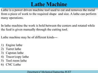
Latheis a power driven machine tool used to cut and removes the metal
from a piece of work to the required shape and size. A lathe can perform
many operations.
In lathe machine the work is hold between the centers and rotated while
the feed is given manually through the cutting tool.
Lathe machine may be of different kinds---
1) Engine lathe
2) Turret lathe
3) Capstan lathe
4) Tracer/copy lathe
5) Tool room lathe
6) CNC Lathe
3.
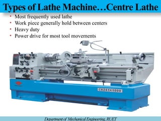
Types of LatheMachine…Centre Lathe
Departmentof MechanicalEngineering,RUET
• Most frequently used lathe
• Work piece generally hold between centers
• Heavy duty
• Power drive for most tool movements
4.
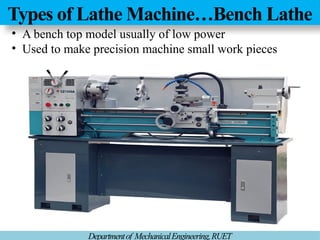
Types of LatheMachine…Bench Lathe
Departmentof MechanicalEngineering,RUET
• A bench top model usually of low power
• Used to make precision machine small work pieces
5.
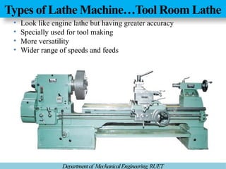
Types of LatheMachine…Tool Room Lathe
Departmentof MechanicalEngineering,RUET
• Look like engine lathe but having greater accuracy
• Specially used for tool making
• More versatility
• Wider range of speeds and feeds
6.
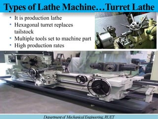
Types of LatheMachine…Turret Lathe
Departmentof MechanicalEngineering,RUET
• It is production lathe
• Hexagonal turret replaces
tailstock
• Multiple tools set to machine part
• High production rates
7.
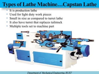
Types of LatheMachine…Capstan Lathe
Departmentof MechanicalEngineering,RUET
• It is production lathe
• Used for light duty work pieces
• Small in size as compared to turret lathe
• It also have turret that replaces tailstock
• Multiple tools set to machine part
8.
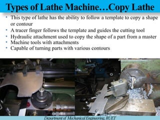
Types of LatheMachine…Copy Lathe
Departmentof MechanicalEngineering,RUET
• This type of lathe has the ability to follow a template to copy a shape
or contour
• A tracer finger follows the template and guides the cutting tool
• Hydraulic attachment used to copy the shape of a part from a master
• Machine tools with attachments
• Capable of turning parts with various contours
9.
Types of LatheMachine…CNC Lathe
Departmentof MechanicalEngineering,RUET
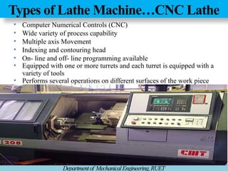
• Computer Numerical Controls (CNC)
• Wide variety of process capability
• Multiple axis Movement
• Indexing and contouring head
• On- line and off- line programming available
• Equipped with one or more turrets and each turret is equipped with a
variety of tools
• Performs several operations on different surfaces of the work piece
10.
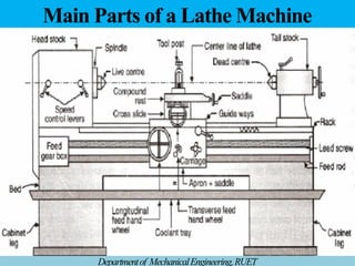
Main Parts ofa Lathe Machine
Departmentof MechanicalEngineering,RUET
11.
Main Parts ofa Lathe Machine… Headstock
Departmentof MechanicalEngineering,RUET
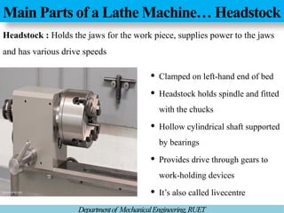
Headstock : Holds the jaws for the work piece, supplies power to the jaws
and has various drive speeds
Clamped on left-hand end of bed
Headstock holds spindle and fitted
with the chucks
Hollow cylindrical shaft supported
by bearings
Provides drive through gears to
work-holding devices
It’s also called livecentre
12.
Main Parts ofa Lathe Machine… Tailstock
Departmentof MechanicalEngineering,RUET
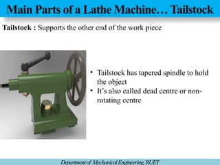
Tailstock : Supports the other end of the work piece
• Tailstock has tapered spindle to hold
the object
• It’s also called dead centre or non-
rotating centre
13.
Main Parts ofa Lathe Machine…Bed
Departmentof MechanicalEngineering,RUET
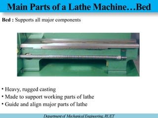
Bed : Supports all major components
• Heavy, rugged casting
• Made to support working parts of lathe
• Guide and align major parts of lathe
14.
Main Parts ofa Lathe Machine… Carriage
Departmentof MechanicalEngineering,RUET
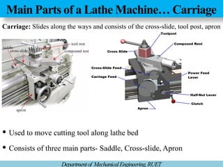
Carriage: Slides along the ways and consists of the cross-slide, tool post, apron
Used to move cutting tool along lathe bed
Consists of three main parts- Saddle, Cross-slide, Apron
15.
MainParts of aLathe Machine…Quick Change GearBox
Departmentof MechanicalEngineering,RUET
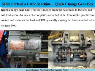
Quick change gear box: Transmits motion from the headstock to the feed rod
and lead screw. An index chart or plate is attached at the front of the gear box to
control and maintain the feed and TPI by swiftly moving the lever attached with
the gear box.
16.
Size of aLathe Machine
Departmentof MechanicalEngineering,RUET
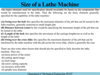
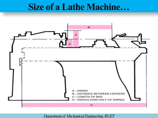
The major elements used for specification should invariably be based on the components that
would be manufactured in the lathe. Thus the following are the basic elements generally
specified for the capability of the lathe machine-
(A) Swing over the bed: this specifies the maximum diameter of the job that can be turned in the
lathe machine, generally restricted to small length jobs
(B) Distance between center's: this would be specifying the maximum length of the job that can
be turned in the lathe.
(C) Length of the bed: this specifies the movement of the carriage lengthwise as well as the
length of the lathe
(D) Swing over the cross slide: this specifies the maximum diameter of the job that can be
machined by the lathe machine with the job across the cross slide, which is generally the case
There are also some other factors that should also be specified to fully describe the lathe
machine. They are-
(a) horse power of the motor
(b) cutting speed range
(c) feed range
(d) screw cutting capacity
(e) accuracy achievable
(f) spindle nose diameter
17.
Size of aLathe Machine…
Departmentof MechanicalEngineering,RUET
18.
Lathe cutting ProcessParameters
Departmentof MechanicalEngineering,RUET
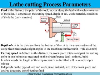
Feed is the distance the point of the tool, moves along the bed with each revolution
of the lathe. It depends on the cutting speed, depth of cut, work material, condition
of the lathe (unit- mm/rev)
Depth of cut is the distance from the bottom of the cut to the uncut surface of the
work piece measured at right angles to the machined surface (unit- t=(D-d)/2 mm)
Cutting speed is defined as the distance the work piece rotates and past the cutting
point in one minute as measured on the circumference (unit- unit rev./min)
In other words the length of the chip measured in feet that will be removed per
minute
It depends on the type of tool and work piece material, size of the work piece and
desired accuracy, use of cutting fluid
19.
Lathe Operations
Departmentof MechanicalEngineering,RUET
LatheMachine Operations.mp4 Lathe Machine Operations_1.mp4
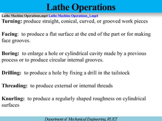
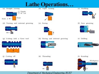
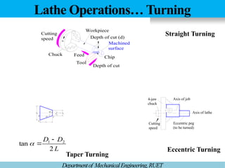
Turning: produce straight, conical, curved, or grooved work pieces
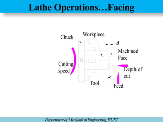
Facing: to produce a flat surface at the end of the part or for making
face grooves.
Boring: to enlarge a hole or cylindrical cavity made by a previous
process or to produce circular internal grooves.
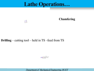
Drilling: to produce a hole by fixing a drill in the tailstock
Threading: to produce external or internal threads
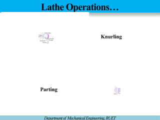
Knurling: to produce a regularly shaped roughness on cylindrical
surfaces
Lathe Operations… Turning
DepartmentofMechanicalEngineering,RUET
C
B
A L
D
90°
2
D1
L
D
D
2
tan 2
1
Axis of job
Axis of lathe
Eccentric peg
(to be turned)
4-jaw
chuck
Cutting
speed
Cutting
speed
Chip
Workpiece
Depth of cut (d)
Depth of cut
Tool
Feed
Chuck
N
Machined
surface
Straight Turning
Taper Turning
Eccentric Turning
Lathe Operations…Threading
Departmentof MechanicalEngineering,RUET
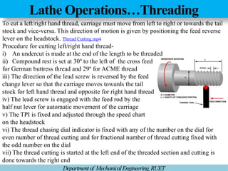
Tocut a left/right hand thread, carriage must move from left to right or towards the tail
stock and vice-versa. This direction of motion is given by positioning the feed reverse
lever on the headstock. Thread Cutting.mp4
Procedure for cutting left/right hand thread-
i) An undercut is made at the end of the length to be threaded
ii) Compound rest is set at 30º to the left of the cross feed
for German buttress thread and 29º for ACME thread
iii) The direction of the lead screw is reversed by the feed
change lever so that the carriage moves towards the tail
stock for left hand thread and opposite for right hand thread
iv) The lead screw is engaged with the feed rod by the
half nut lever for automatic movement of the carriage
v) The TPI is fixed and adjusted through the speed chart
on the headstock
vi) The thread chasing dial indicator is fixed with any of the number on the dial for
even number of thread cutting and for fractional number of thread cutting fixed with
the odd number on the dial
vii) The thread cutting is started at the left end of the threaded section and cutting is
done towards the right end
26.
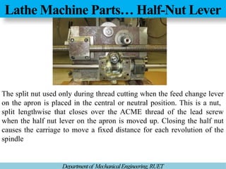
Lathe Machine Parts…Half-Nut Lever
Departmentof MechanicalEngineering,RUET
The split nut used only during thread cutting when the feed change lever
on the apron is placed in the central or neutral position. This is a nut,
split lengthwise that closes over the ACME thread of the lead screw
when the half nut lever on the apron is moved up. Closing the half nut
causes the carriage to move a fixed distance for each revolution of the
spindle
27.
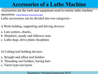
Accessories of aLathe Machine
Departmentof MechanicalEngineering,RUET
Accessories are the tools and equipment used in routine lathe machine
operations. Lathe Machine Accessories.mp4
Lathe accessories can be divided into two categories –
i) Work holding, supporting and driving devices-
a. Late centers, chucks,
b. Mandrels, steady and follower rests
c. Lathe dogs, drive plates faceplates
ii) Cutting tool holding devices-
a. Straight and offset tool holders
b. Threading tool holders, boring bars
c. Turret-type tool posts
28.
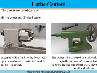
Lathe Centers
Departmentof MechanicalEngineering,RUET
Thereare two types of centers-
(i) live center and (ii) dead center
A center which fits into the headstock
spindle and revolves with the work is
called live center.
The center which is used in a tailstock
spindle and doesn’t revolve but
support the free end of the work piece
is called dead center
29.
Lathe Chucks
Departmentof MechanicalEngineering,RUET
Chucksare important device used for holding work pieces. It is attached
to the lathe spindle by means of two bolts with the back plate screwed on
the spindle nose.
There are many type of the chuck, but the following three are commonly
used –
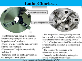
i. Three jaw universal chuck
ii. Four jaw independent chuck
iii. Magnetic chuck
iv. Collet chuck
30.
Lathe Chucks…
Departmentof MechanicalEngineering,RUET
-The three jaw can move by inserting
the chuck key at any of the 3- holes on
the periphery of the chuck
- The 3- jaw moves in the same direction
with the same velocity
- The centre of the jobs automatically
established
- Generally used for holding cylindrical
and hexagonal work pieces
- The independent chuck generally has four
jaws , which are adjusted individually on the
chuck face by means of adjusting screws
- Each of the jaw moves in different direction
by inserting the chuck key at the respective
jaw hole
- The centre of the jobs need to be
determined by the operators
- Generally used for holding rectangular,
square or unsymmetrical objects
3-jaw universal chuck
4-jaw independent chuck
31.
Lathe Chucks…
Departmentof MechanicalEngineering,RUET
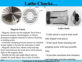
-Magnetic chucks use the magnetic force from a
permanent magnet, electromagnet, or electro-
permanent magnetic material to achieve chucking
or holding action
- Consistent clamping pressure ensures no variation
in how tightly or loosely the work piece is held
- Magnetic chucks have shorter setup and take
down times because the work piece can be placed
right on the magnetic plate
- Suitable for thin and rough objects and not
suitable for small objects due to lack of surface
area
- Collet chuck is used to hold small
tube shaped work pieces
- It has much faster releasing and
gripping action with least possible
time
- It provides maximum tool clearance
and automatic accurate centering
Magnetic Chuck Collet Chuck
32.
LatheAccessories… Drive Plate
DepartmentofMechanicalEngineering,RUET
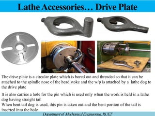
The drive plate is a circular plate which is bored out and threaded so that it can be
attached to the spindle nose of the head stoke and the w/p is attached by a lathe dog to
the drive plate
It is also carries a hole for the pin which is used only when the work is held in a lathe
dog having straight tail
When bent tail dog is used, this pin is taken out and the bent portion of the tail is
inserted into the hole
33.
LatheAccessories… Face Plate
DepartmentofMechanicalEngineering,RUET
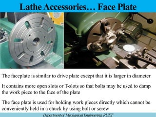
The faceplate is similar to drive plate except that it is larger in diameter
It contains more open slots or T-slots so that bolts may be used to damp
the work piece to the face of the plate
The face plate is used for holding work pieces directly which cannot be
conveniently held in a chuck by using bolt or screw
34.
LatheAccessories… Mandrels
Departmentof MechanicalEngineering,RUET
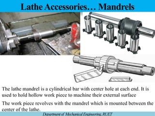
Thelathe mandrel is a cylindrical bar with center hole at each end. It is
used to hold hollow work piece to machine their external surface
The work piece revolves with the mandrel which is mounted between the
center of the lathe.
35.
LatheAttachments…Taper turning Operations
DepartmentofMechanicalEngineering,RUET
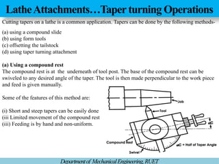
Cutting tapers on a lathe is a common application. Tapers can be done by the following methods-
(a) using a compound slide
(b) using form tools
(c) offsetting the tailstock
(d) using taper turning attachment
(a) Using a compound rest
The compound rest is at the underneath of tool post. The base of the compound rest can be
swiveled to any desired angle of the taper. The tool is then made perpendicular to the work piece
and feed is given manually.
Some of the features of this method are:
(i) Short and steep tapers can be easily done
(iii Limited movement of the compound rest
(iii) Feeding is by hand and non-uniform.
36.
LatheAttachments…Taper turning Operations
DepartmentofMechanicalEngineering,RUET
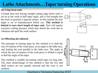
(b) Using form tools
A broad nose tool having straight cutting edge (form tool) is
set on to the work at half taper angle, and is fed straight into
the work to generate a tapered surface. In this method the tool
angle is set or manufactured before use. This method is
limited to turn short length of taper only. Tool will require
excessive cutting pressure which may distort the work due to
vibration and spoil the work surface.
The principle of turning taper by this method is to shift the
axis of rotation of the work piece, at an angle to the lathe axis,
and feeding the tool parallel to the lathe axis. The angle at
which the axis of rotation of the work piece is shifted is equal
to half the angle of the taper.
This method is suitable for turning small taper on long jobs.
The main disadvantage of this method is that the live and
dead centers are not equally stressed and the wear is not
uniform.
(c) Offsetting the tailstock
37.
LatheAttachments…Taper turning Operations
DepartmentofMechanicalEngineering,RUET
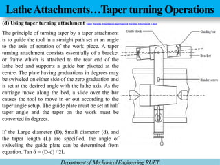
The principle of turning taper by a taper attachment
is to guide the tool in a straight path set at an angle
to the axis of rotation of the work piece. A taper
turning attachment consists essentially of a bracket
or frame which is attached to the rear end of the
lathe bed and supports a guide bar pivoted at the
centre. The plate having graduations in degrees may
be swiveled on either side of the zero graduation and
is set at the desired angle with the lathe axis. As the
carriage move along the bed, a slide over the bar
causes the tool to move in or out according to the
taper angle setup. The guide plate must be set at half
taper angle and the taper on the work must be
converted in degrees.
If the Large diameter (D), Small diameter (d), and
the taper length (L) are specified, the angle of
swiveling the guide plate can be determined from
equation. Tan ά = (D-d) / 2L
(d) Using taper turning attachment Taper Turning Attachment.mp4Tapered Turning Attachment 1.mp4
38.
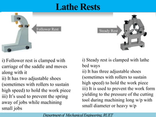
Lathe Rests
Departmentof MechanicalEngineering,RUET
SteadyRest
Follower Rest
i) Follower rest is clamped with
carriage of the saddle and moves
along with it
ii) It has two adjustable shoes
(sometimes with rollers to sustain
high speed) to hold the work piece
iii) It’s used to prevent the spring
away of jobs while machining
small jobs
i) Steady rest is clamped with lathe
bed ways
ii) It has three adjustable shoes
(sometimes with rollers to sustain
high speed) to hold the work piece
iii) It is used to prevent the work form
yielding to the pressure of the cutting
tool during machining long w/p with
small diameter or heavy w/p
39.
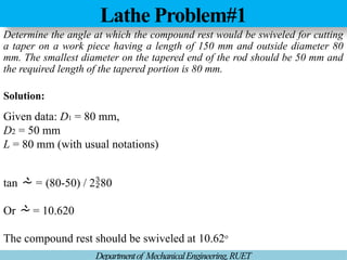
Lathe Problem#1
Departmentof MechanicalEngineering,RUET
Determinethe angle at which the compound rest would be swiveled for cutting
a taper on a work piece having a length of 150 mm and outside diameter 80
mm. The smallest diameter on the tapered end of the rod should be 50 mm and
the required length of the tapered portion is 80 mm.
Solution:
Given data: D1 = 80 mm,
D2 = 50 mm
L = 80 mm (with usual notations)
tan = (80-50) / 280
Or = 10.620
The compound rest should be swiveled at 10.62o
40.
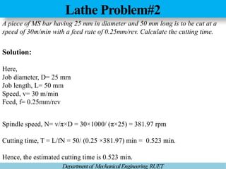
Lathe Problem#2
Departmentof MechanicalEngineering,RUET
Apiece of MS bar having 25 mm in diameter and 50 mm long is to be cut at a
speed of 30m/min with a feed rate of 0.25mm/rev. Calculate the cutting time.
Solution:
Here,
Job diameter, D= 25 mm
Job length, L= 50 mm
Speed, v= 30 m/min
Feed, f= 0.25mm/rev
Spindle speed, N= v/π×D = 30×1000/ (π×25) = 381.97 rpm
Cutting time, T = L/fN = 50/ (0.25 ×381.97) min = 0.523 min.
Hence, the estimated cutting time is 0.523 min.
41.
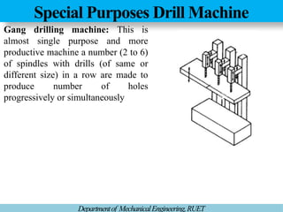
Special Purposes DrillMachine
Departmentof MechanicalEngineering,RUET
Gang drilling machine: This is
almost single purpose and more
productive machine a number (2 to 6)
of spindles with drills (of same or
different size) in a row are made to
produce number of holes
progressively or simultaneously
42.
Special Purposes DrillMachine
Departmentof MechanicalEngineering,RUET
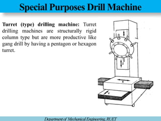
Turret (type) drilling machine: Turret
drilling machines are structurally rigid
column type but are more productive like
gang drill by having a pentagon or hexagon
turret.
43.
Special Purposes DrillMachine
Departmentof MechanicalEngineering,RUET
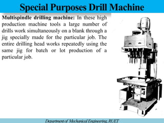
Multispindle drilling machine: In these high
production machine tools a large number of
drills work simultaneously on a blank through a
jig specially made for the particular job. The
entire drilling head works repeatedly using the
same jig for batch or lot production of a
particular job.
44.
Lathe Problem#3
Departmentof MechanicalEngineering,RUET
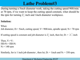
Duringturning a 5inch diameter work, taking the cutting speed 90ft/min.
at 70 rpm, if we want to keep the cutting speed constant, what should be
the rpm for turning 2 inch and 1inch diameter workpiece.
Solution:
2
1
When
Job diameter, D1= 5inch, cutting speed, V= 90ft/min, spindle speed, N1= 70 rpm
If cutting speed is constant and job diameter is 2 inch, then let, D2 = 2 inch
Then, V1=V2
ΠD1N1= ΠD2N2
N2 = 140 rpm
Similarly, for is 1 inch job diameter , then let, D3 = 1inch and N3 = 350 rpm.
2
1
2
1