Downloaded 3,578 times


![Sr.No Comparison
Parameter
Arithmetic Progression Geometric
Progression
Harmonic Progression
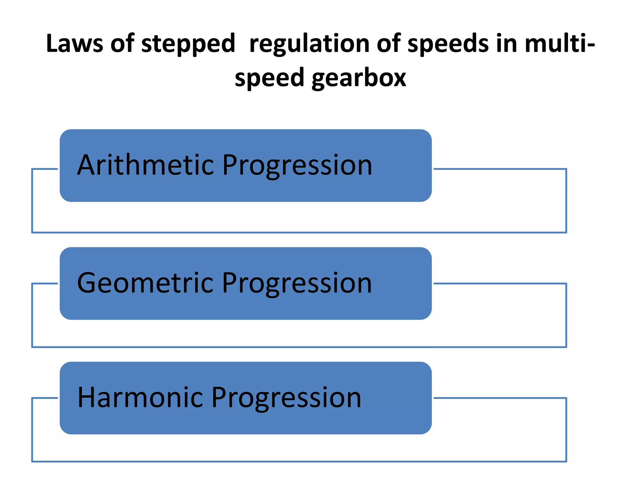
1 Definition In arithmetic
progression, the
difference between
any two successive
spindle speeds is
constant.
In geometric
progression, the
ratio of any two
successive spindle
speeds is constant.
In harmonic
progression, the
difference between
reciprocal of any two
successive speeds is
constant.
2 Zth Spindle
Speed 𝑛 𝑧 =
𝑛 𝑚𝑎𝑥 − 𝑛𝑚𝑖𝑛
(𝑧 − 1)
∅ =
𝑛 𝑚𝑎𝑥
𝑛 𝑚𝑖𝑛
1
𝑧−1
𝑛𝑧 =
𝑛 𝑚𝑖𝑛
[1 − 𝑧 − 1 𝐶𝑛 𝑚𝑎𝑥]
3 Good in High spindle speed
range
High spindle speed
range
Low spindle speed
range
4 Poor in Low spindle speed
range
Low spindle speed
range
High spindle speed
range](https://image.slidesharecdn.com/mdgearbox-160929095807/75/Design-of-Gear-Box-11-2048.jpg)


![Cont…
8. Now the permissible speed variation
is = ±10 ∅ − 1 %
= ±10 [1.25-1]
= ±2.5%
i.e. Maximum 5% variation
Here the percentage variation variation is more
or less within
the permissible value.](https://image.slidesharecdn.com/mdgearbox-160929095807/75/Design-of-Gear-Box-35-2048.jpg)


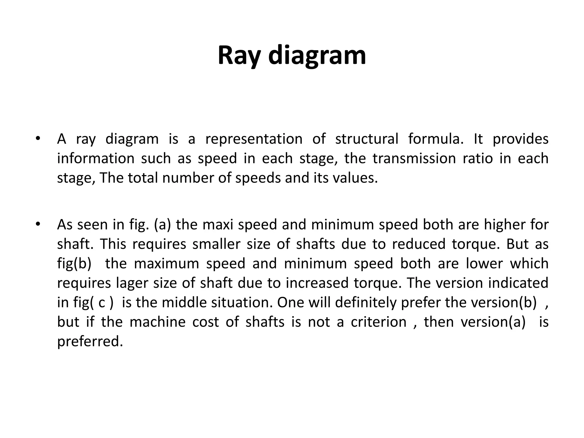
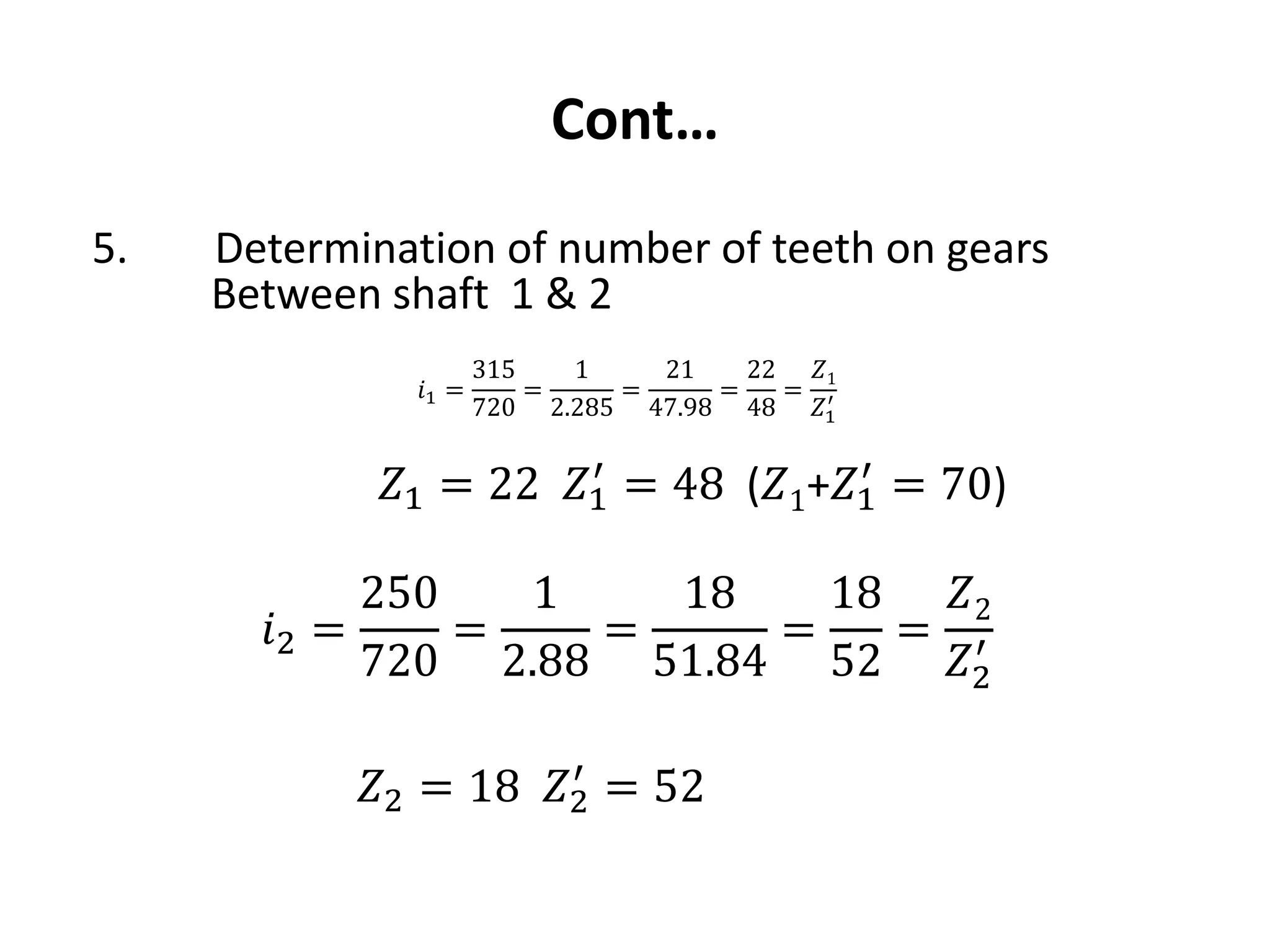
The document provides a comprehensive overview of gearboxes, detailing their functions and components, specifically in relation to automobiles. It discusses design procedures for multi-speed gearboxes, including laws of speed regulation and the necessary diagrams for representation. An example is presented for designing a gearbox with specific speed and torque requirements, emphasizing practical application in engineering.


![CleanMyMac X v5.2.8 Crack for MacOS Full Version [Latest] pptx](https://cdn.slidesharecdn.com/ss_thumbnails/softwareoverview-251207194121-a81f0142-thumbnail.jpg?width=640&height=640&fit=bounds)
![Soundtoys Mac v5.5.5.0 Crack for MacOS Full Version [Latest] pptx](https://cdn.slidesharecdn.com/ss_thumbnails/softwareoverview-251207193711-91d8ae6b-thumbnail.jpg?width=640&height=640&fit=bounds)


