Downloaded 1,692 times


![Translational Mechanical System
Transfer Function
How do we get the equation?
Answer:
[sum of impedances]X(s) = [sum of applied forces]
Movement to the left is positive](https://image.slidesharecdn.com/controlchap2-131231194102-phpapp01/85/Control-chap2-62-320.jpg)


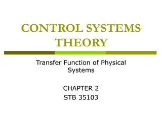
![Rotational Mechanical System
Transfer Functions
We will use
[sum of impedances]θ(s) = [sum of applied torque]
Based on the free body diagram, the
equation of motion is
( Js
2
)
+ Ds + K θ ( s ) = T ( s )
θ ( s)
we know transfer function, G ( s), is
T ( s)
θ (s)
1
= 2
T ( s ) Js + Ds + K
1
J
=
D
K
2
s + s+
J
J](https://image.slidesharecdn.com/controlchap2-131231194102-phpapp01/85/Control-chap2-78-320.jpg)


![Laplace transform review
The Laplace transform is defined as
∞
ℒ[ f (t )] = F (s) = ∫
f (t )e − st dt
0−
Where s = σ + jω
Inverse Laplace transform, to get f(t) given
F(s), is
σ + j∞
1
−1
st
ℒ [ F ( s)] = 2π j ∫ F ( s)e ds
σ − j∞](https://image.slidesharecdn.com/controlchap2-131231194102-phpapp01/85/Control-chap2-82-320.jpg)


Here are the steps to solve for the transfer function G(s) = X2(s)/F(s) for the given system: 1. Draw the free body diagrams for both masses M1 and M2 showing all the forces acting on each mass. 2. Write the Newton's second law equation for M1: (M1s2 + f1vs + k1)X1(s) - k2(X1(s) - X2(s)) = 0 3. Write the Newton's second law equation for M2: -k2(X1(s) - X2(s)) + (M2s2 + f2vs + k


![Reduction of multiple subsystem [compatibility mode]](https://cdn.slidesharecdn.com/ss_thumbnails/reductionofmultiplesubsystemcompatibilitymode-110418075355-phpapp01-thumbnail.jpg?width=640&height=640&fit=bounds)


![Circuit Network Analysis - [Chapter5] Transfer function, frequency response, ...](https://cdn.slidesharecdn.com/ss_thumbnails/ch5-150613063859-lva1-app6891-thumbnail.jpg?width=640&height=640&fit=bounds)