2
Outline of thisLecture
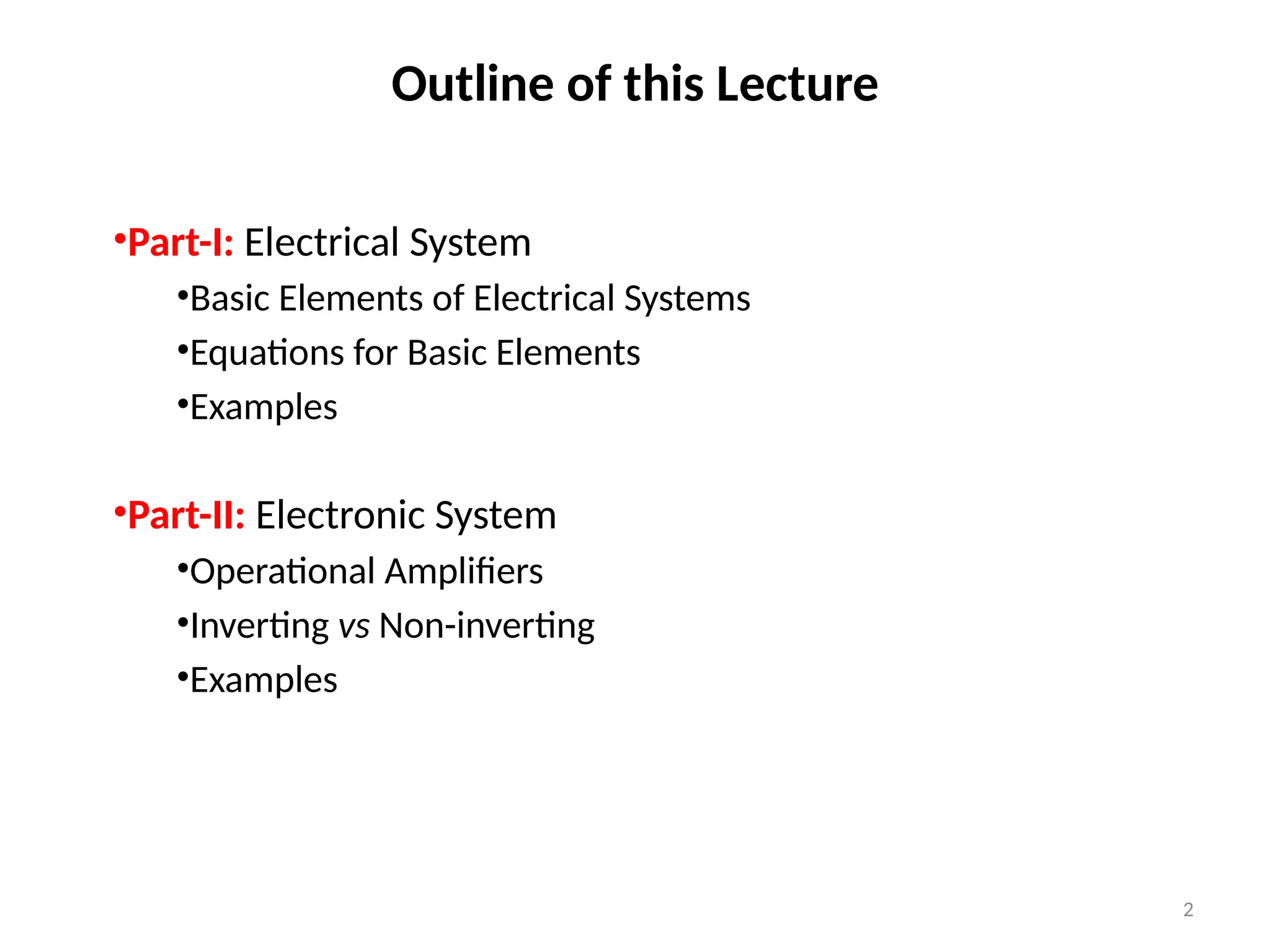
•Part-I: Electrical System
•Basic Elements of Electrical Systems
•Equations for Basic Elements
•Examples
•Part-II: Electronic System
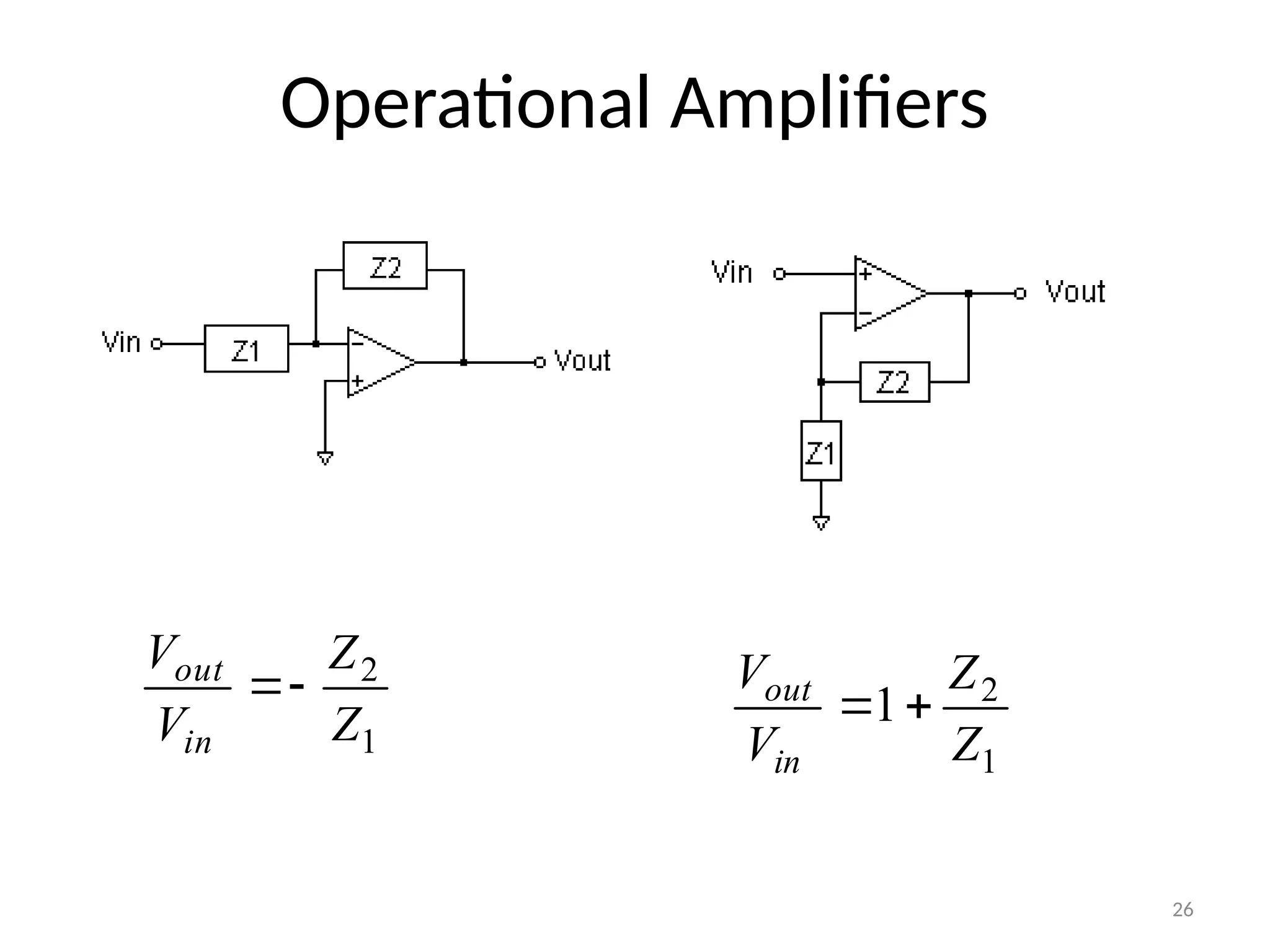
•Operational Amplifiers
•Inverting vs Non-inverting
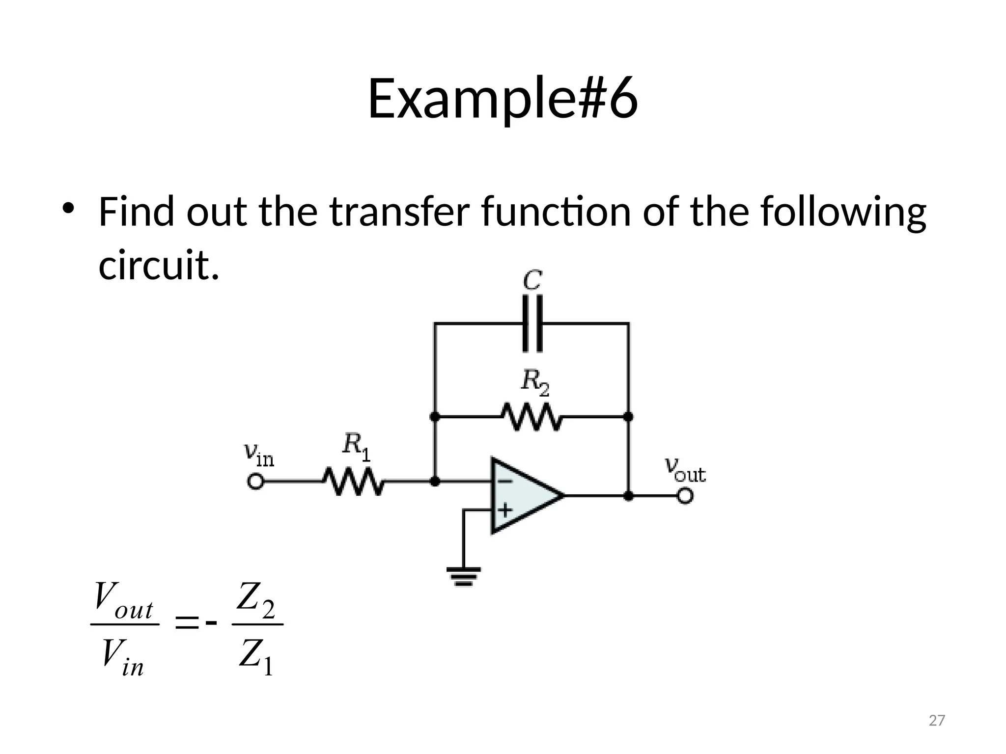
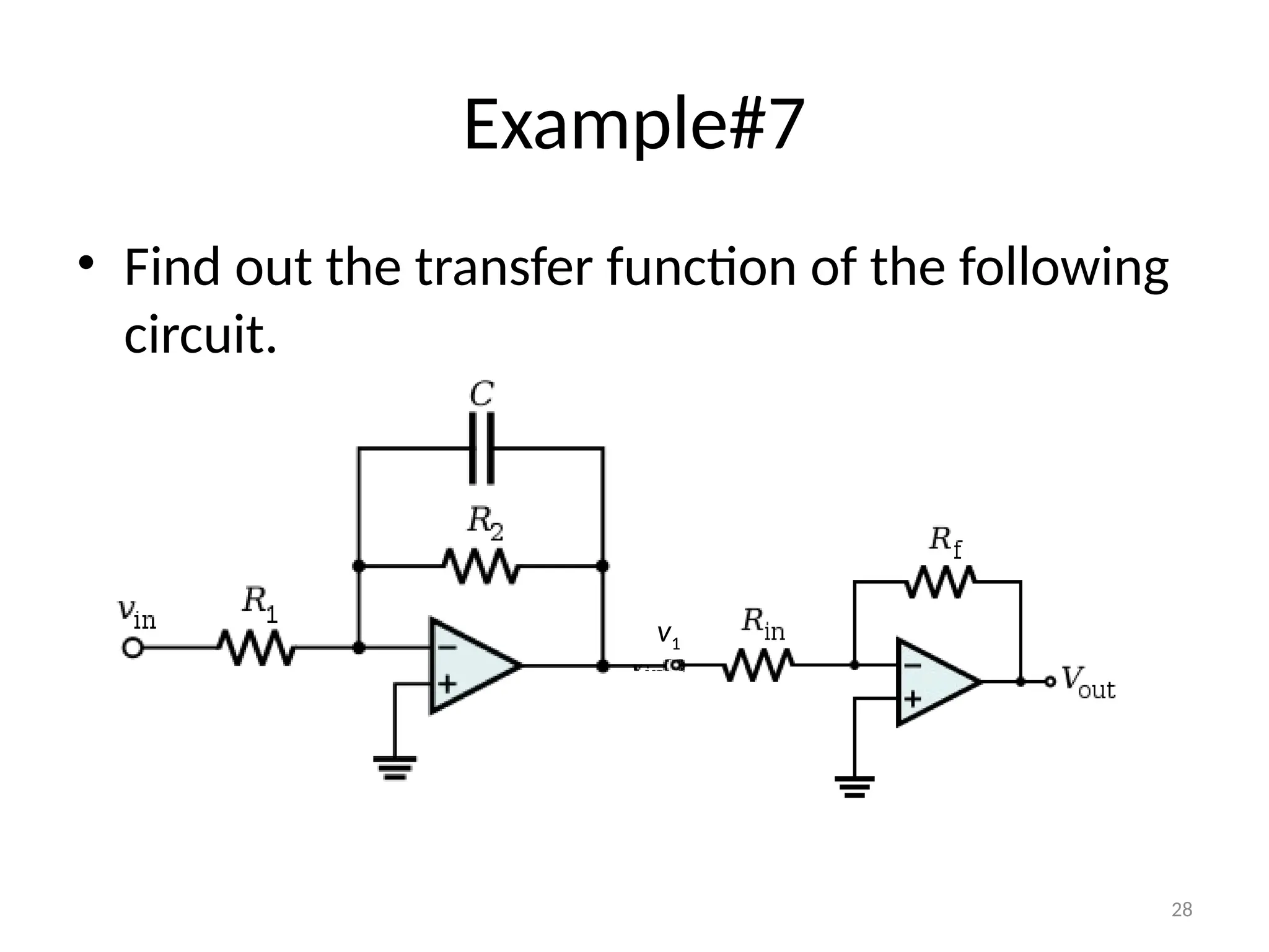
•Examples
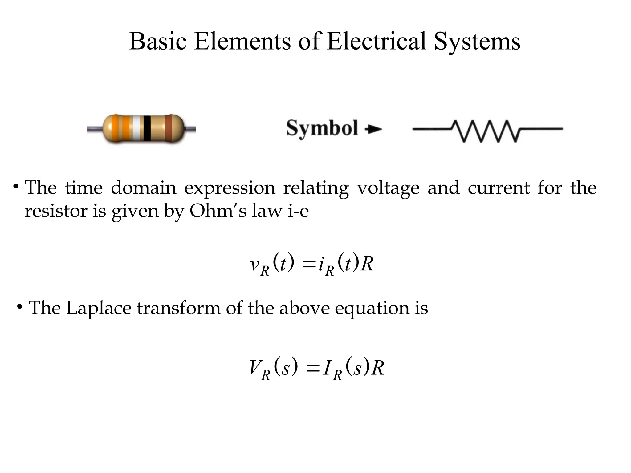
Basic Elements ofElectrical Systems
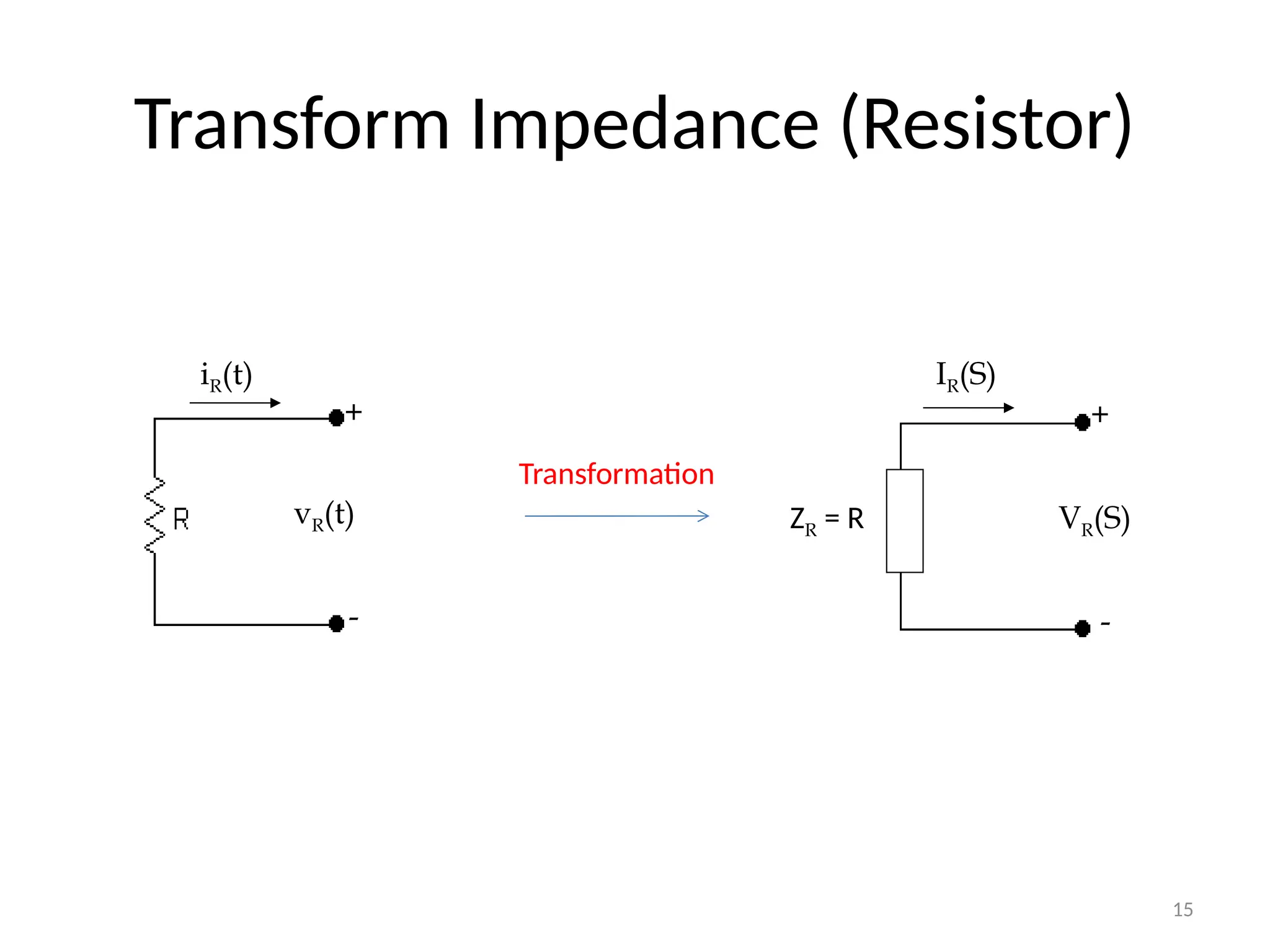
• The time domain expression relating voltage and current for the
resistor is given by Ohm’s law i-e
R
t
i
t
v R
R )
(
)
(
• The Laplace transform of the above equation is
R
s
I
s
V R
R )
(
)
(
5.
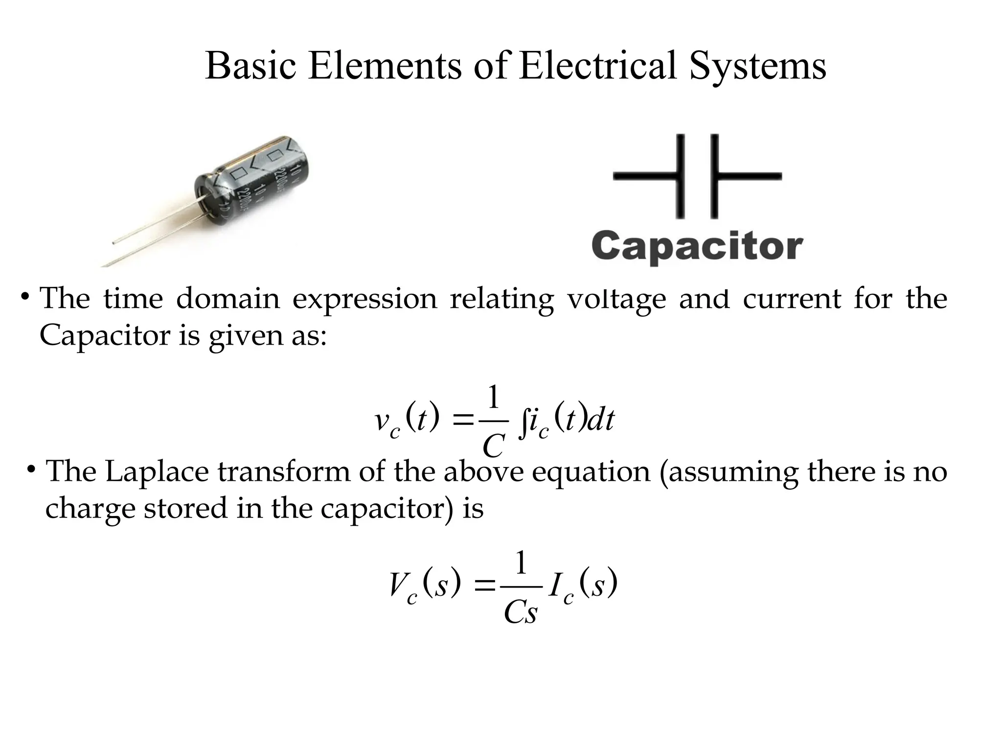
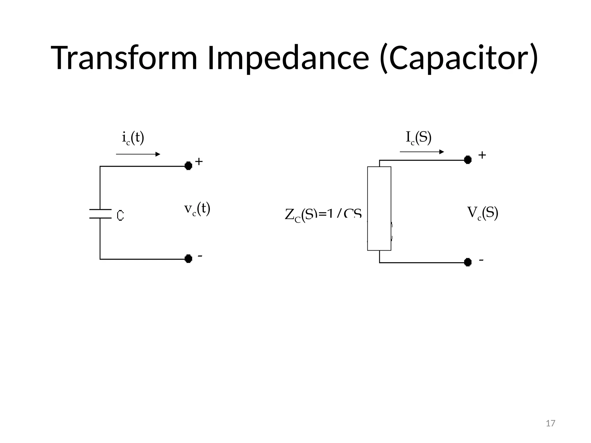
Basic Elements ofElectrical Systems
• The time domain expression relating voltage and current for the
Capacitor is given as:
dt
t
i
C
t
v c
c
)
(
)
(
1
• The Laplace transform of the above equation (assuming there is no
charge stored in the capacitor) is
)
(
)
( s
I
Cs
s
V c
c
1
6.
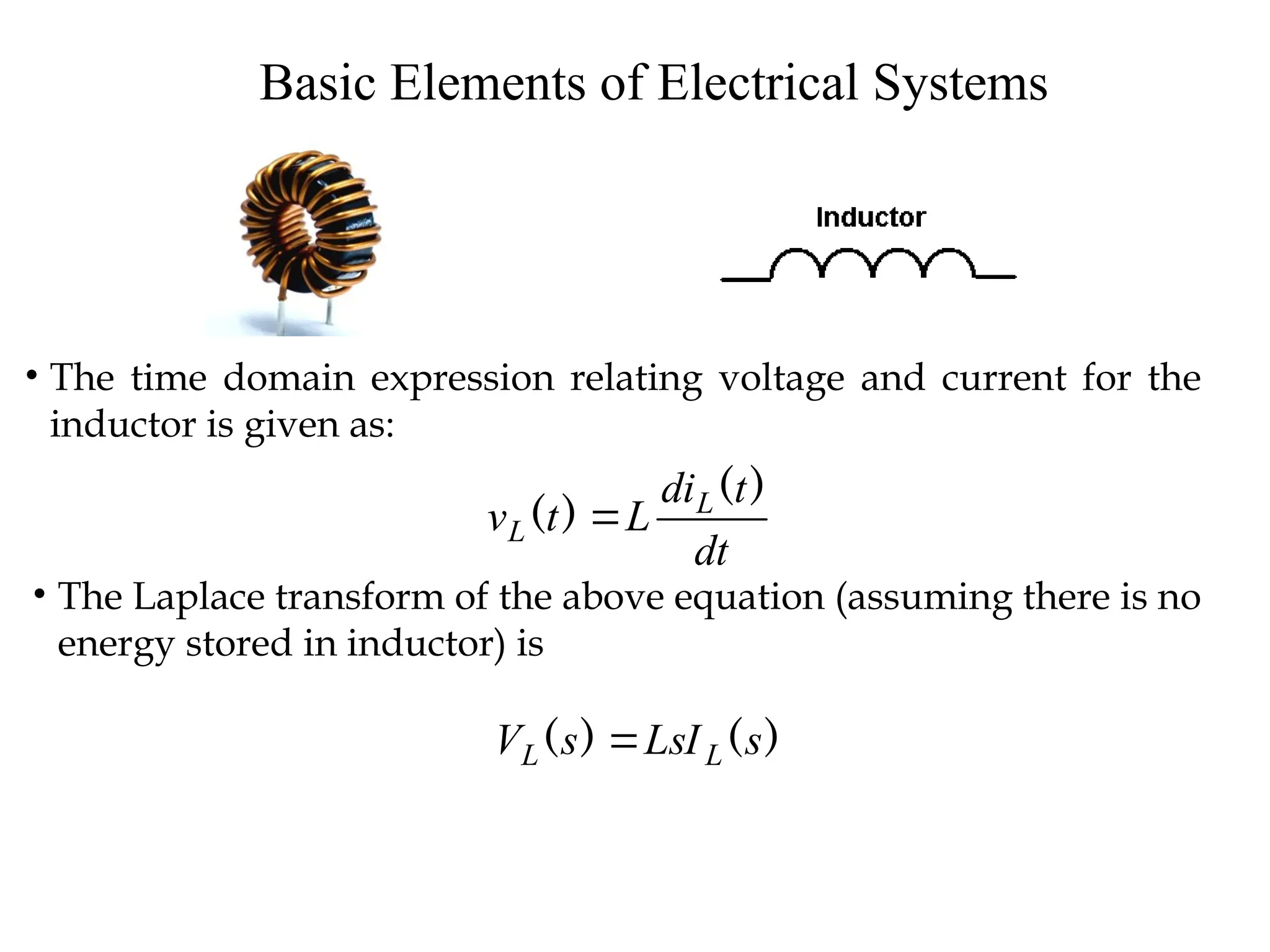
Basic Elements ofElectrical Systems
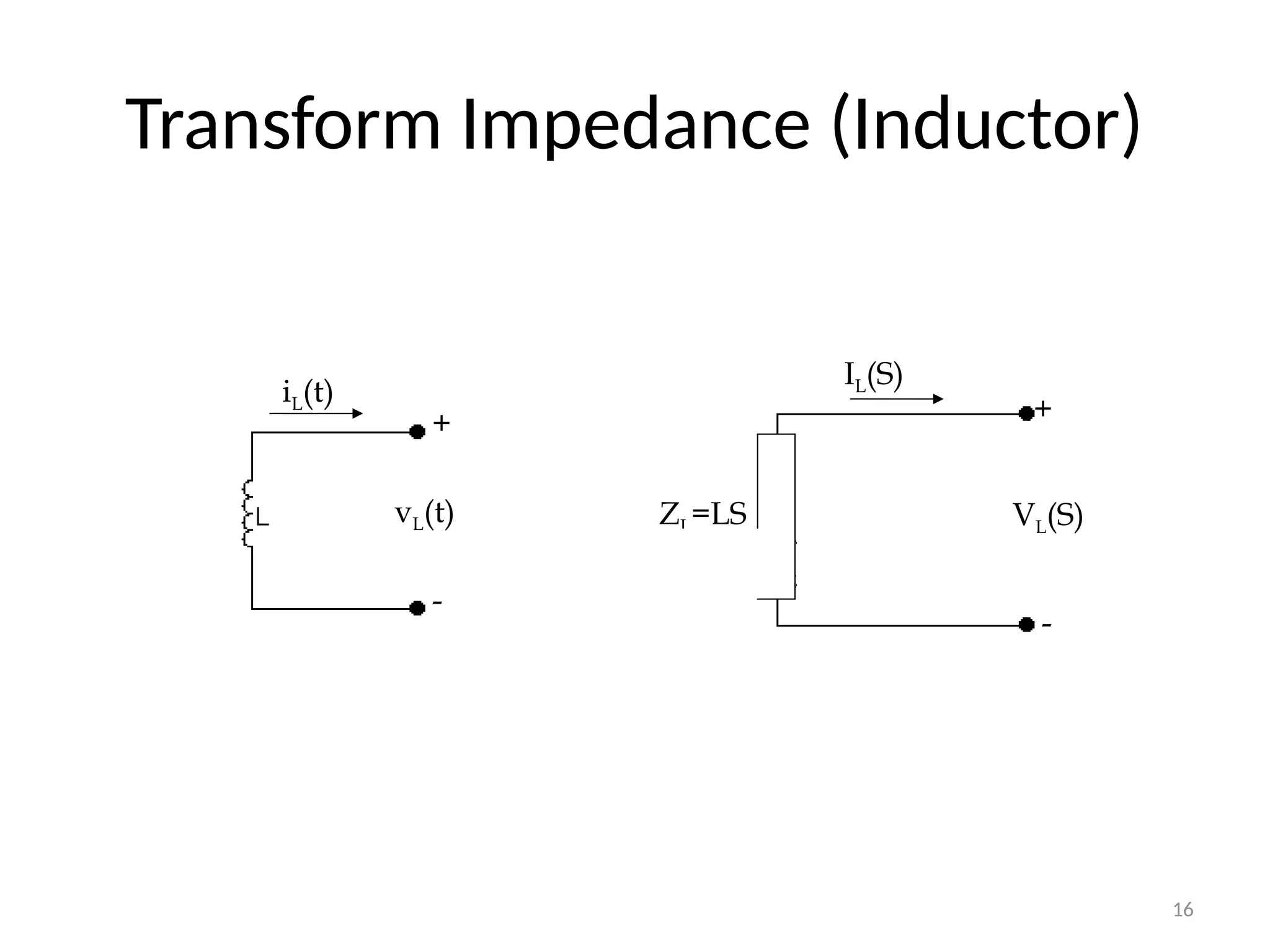
• The time domain expression relating voltage and current for the
inductor is given as:
dt
t
di
L
t
v L
L
)
(
)
(
• The Laplace transform of the above equation (assuming there is no
energy stored in inductor) is
)
(
)
( s
LsI
s
V L
L
7.
7
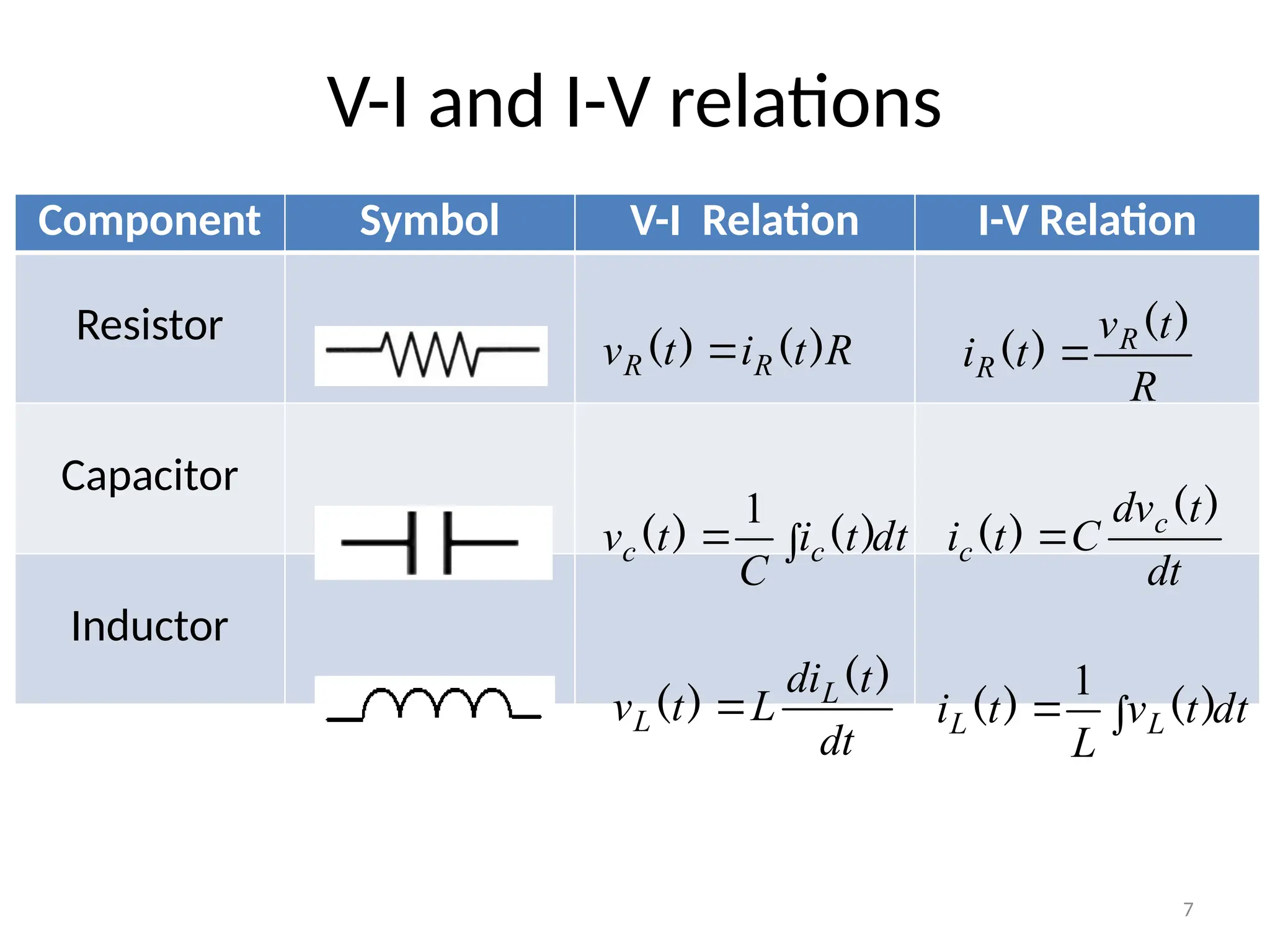
V-I and I-Vrelations
Component Symbol V-I Relation I-V Relation
Resistor
Capacitor
Inductor
dt
t
di
L
t
v L
L
)
(
)
(
dt
t
i
C
t
v c
c
)
(
)
(
1
R
t
i
t
v R
R )
(
)
(
R
t
v
t
i R
R
)
(
)
(
dt
t
dv
C
t
i c
c
)
(
)
(
dt
t
v
L
t
i L
L
)
(
)
(
1
8.
8
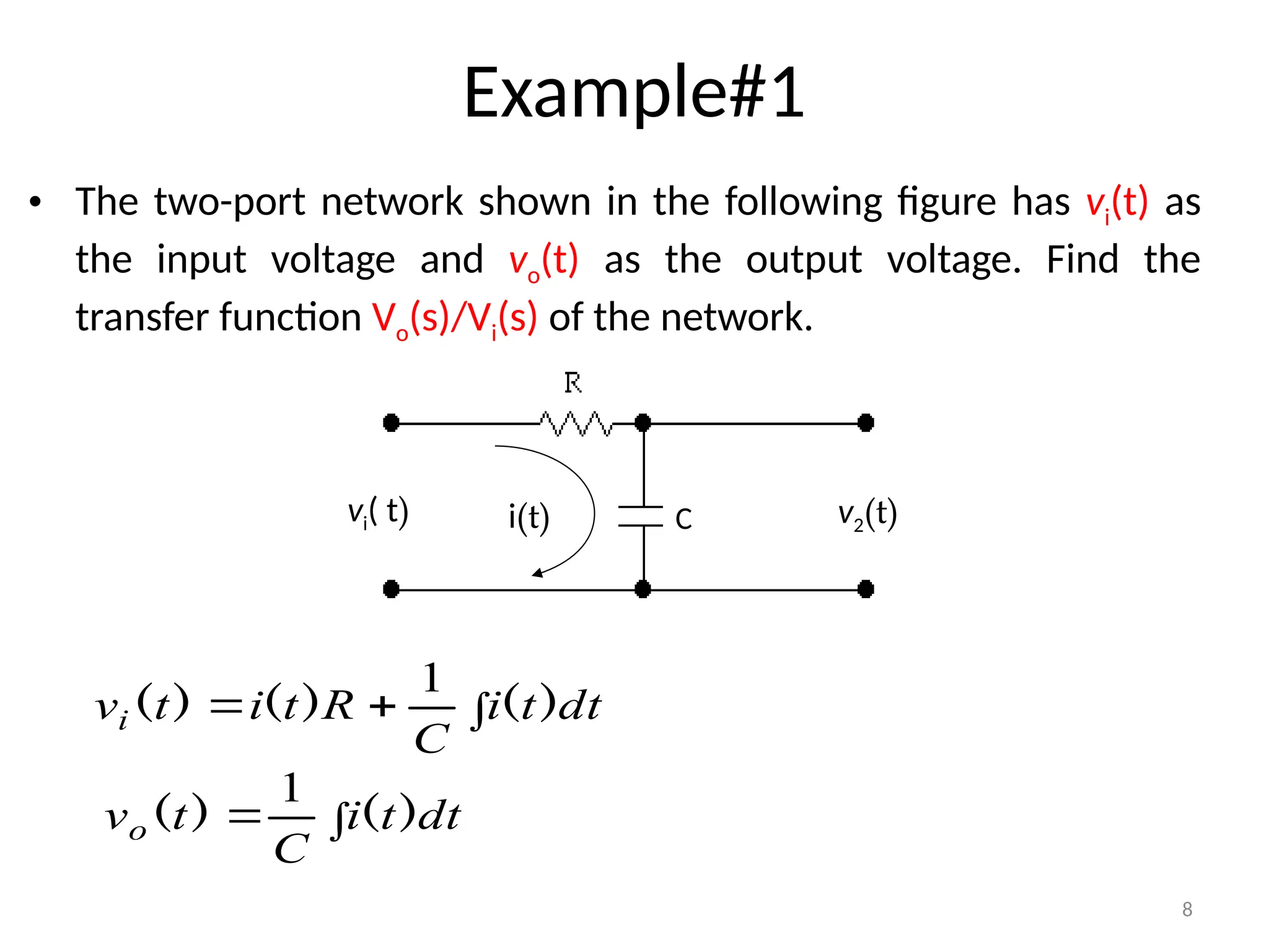
Example#1
• The two-portnetwork shown in the following figure has vi(t) as
the input voltage and vo(t) as the output voltage. Find the
transfer function Vo(s)/Vi(s) of the network.
C
i(t)
vi( t) v2(t)
dt
t
i
C
R
t
i
t
vi )
(
)
(
)
(
1
dt
t
i
C
t
vo )
(
)
(
1
9.
9
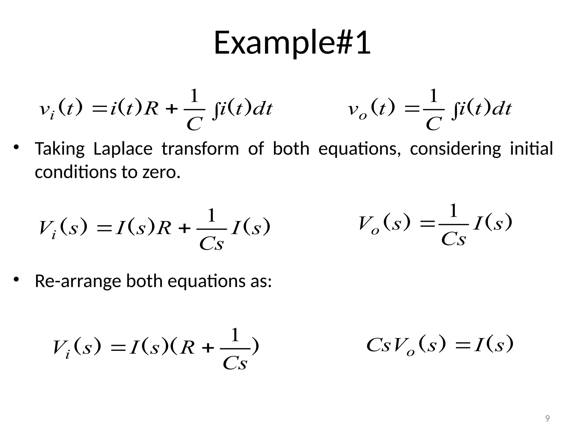
Example#1
• Taking Laplacetransform of both equations, considering initial
conditions to zero.
• Re-arrange both equations as:
dt
t
i
C
R
t
i
t
vi )
(
)
(
)
(
1
dt
t
i
C
t
vo )
(
)
(
1
)
(
)
(
)
( s
I
Cs
R
s
I
s
Vi
1
)
(
)
( s
I
Cs
s
Vo
1
)
(
)
( s
I
s
CsVo
)
)(
(
)
(
Cs
R
s
I
s
Vi
1
10.
10
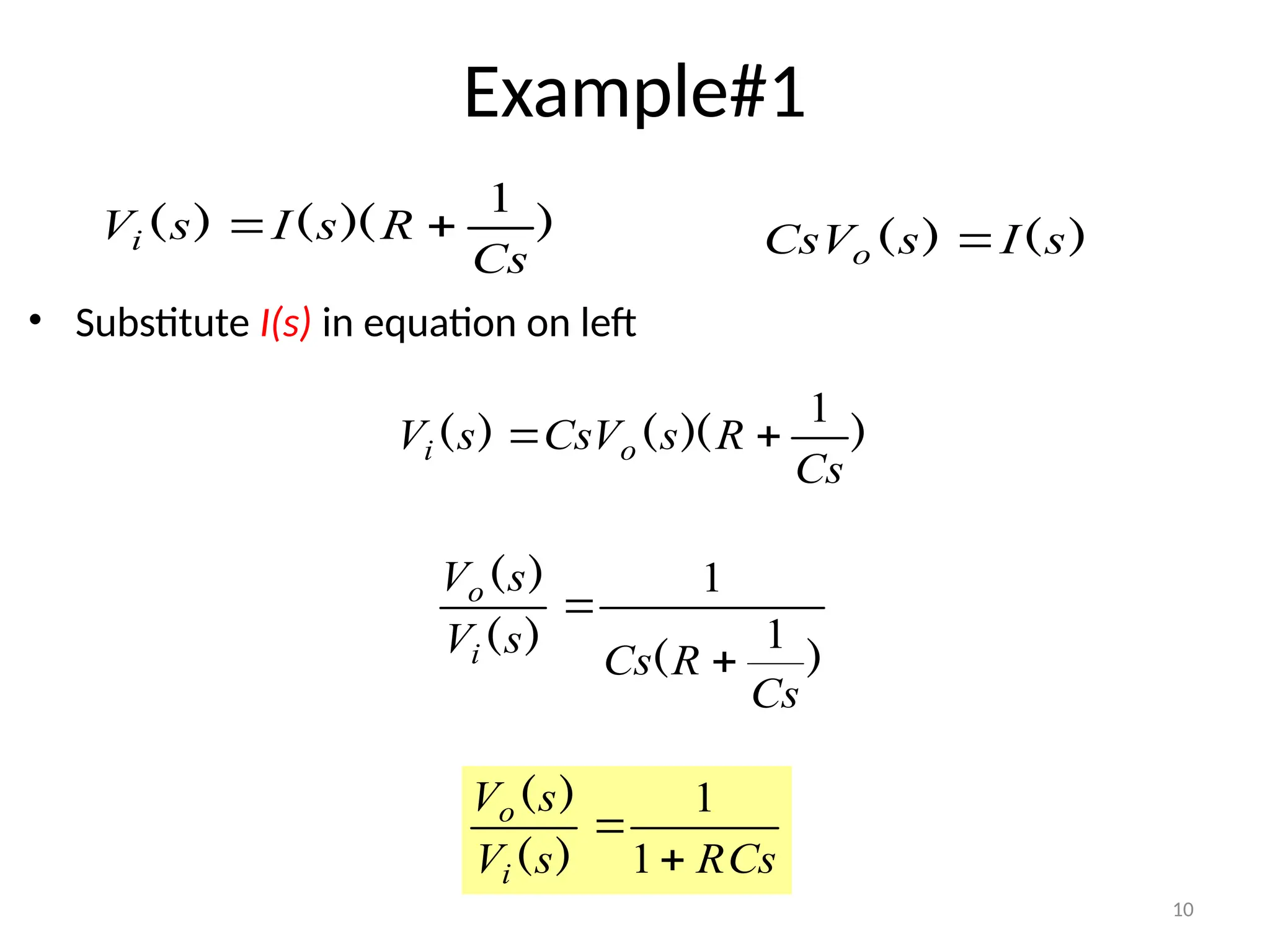
Example#1
• Substitute I(s)in equation on left
)
(
)
( s
I
s
CsVo
)
)(
(
)
(
Cs
R
s
I
s
Vi
1
)
)(
(
)
(
Cs
R
s
CsV
s
V o
i
1
)
(
)
(
)
(
Cs
R
Cs
s
V
s
V
i
o
1
1
RCs
s
V
s
V
i
o
1
1
)
(
)
(
12
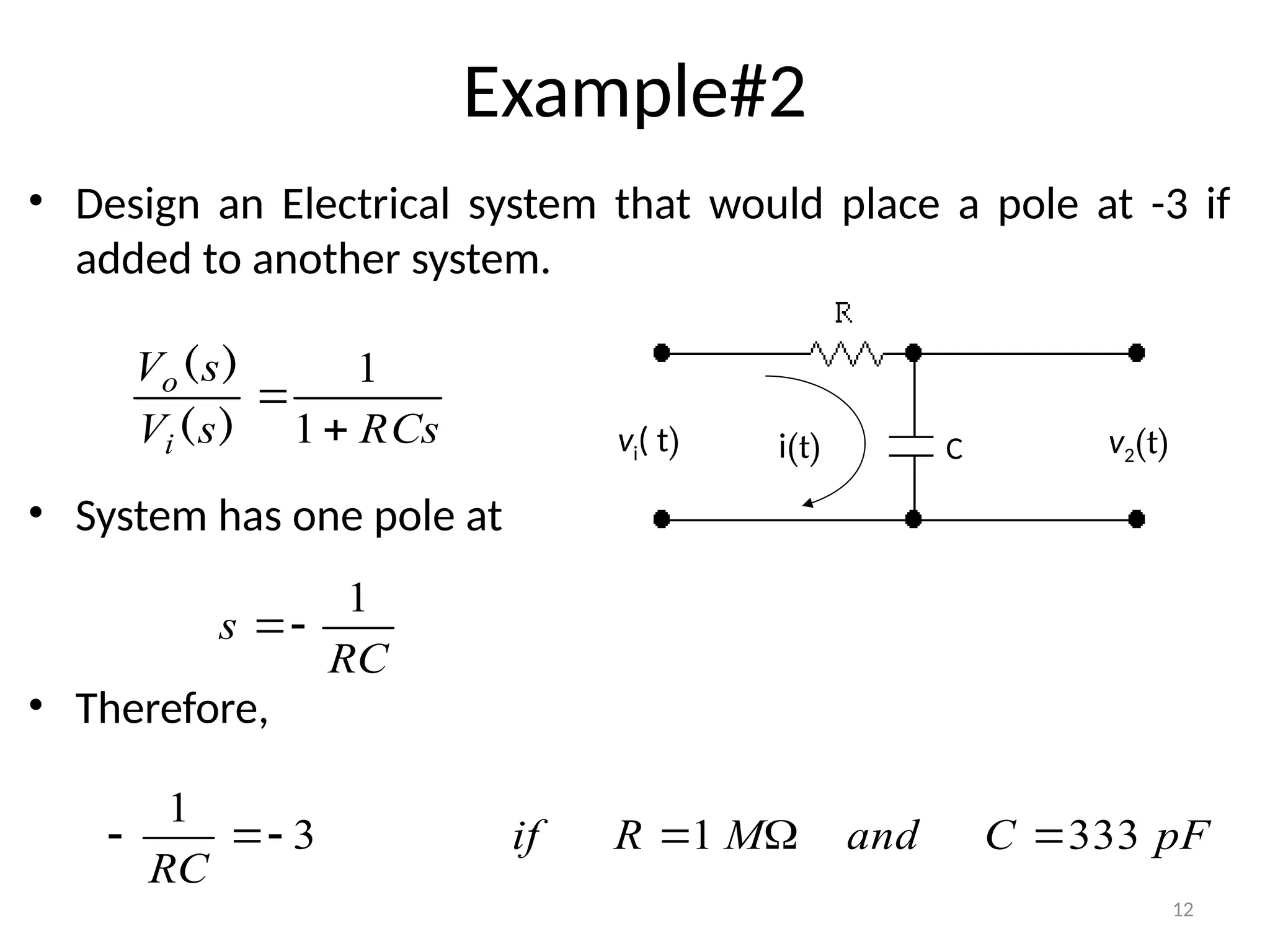
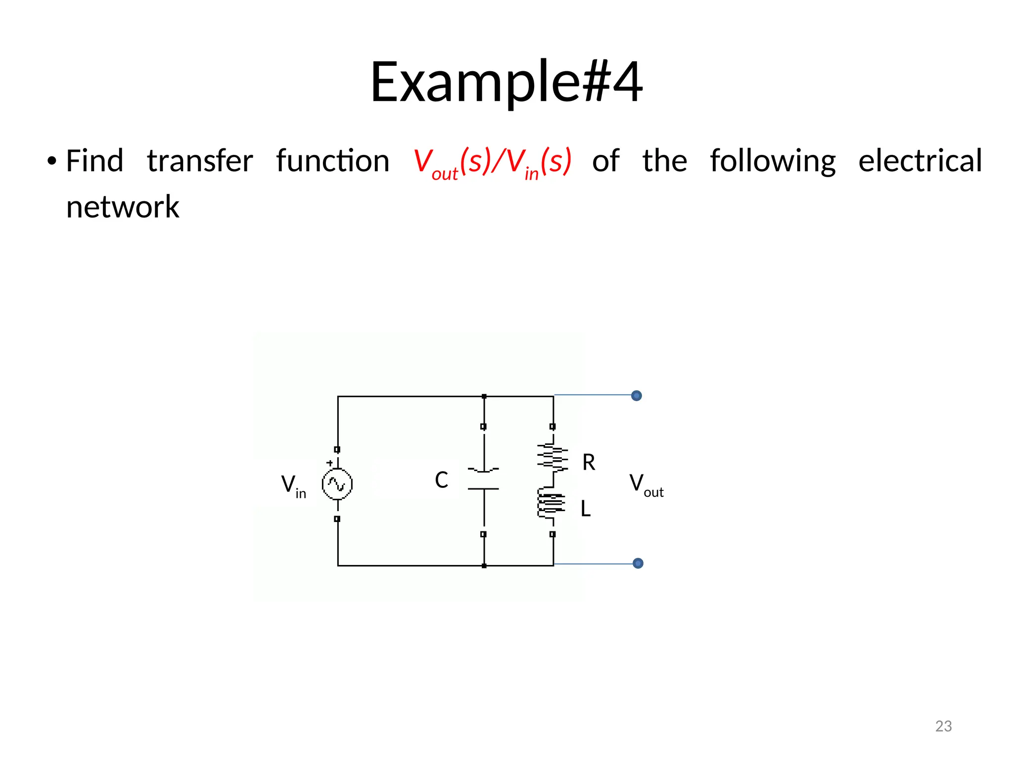
Example#2
• Design anElectrical system that would place a pole at -3 if
added to another system.
• System has one pole at
• Therefore,
C
i(t)
vi( t) v2(t)
RCs
s
V
s
V
i
o
1
1
)
(
)
(
RC
s
1
3
1
RC
pF
C
and
M
R
if 333
1
13.
13
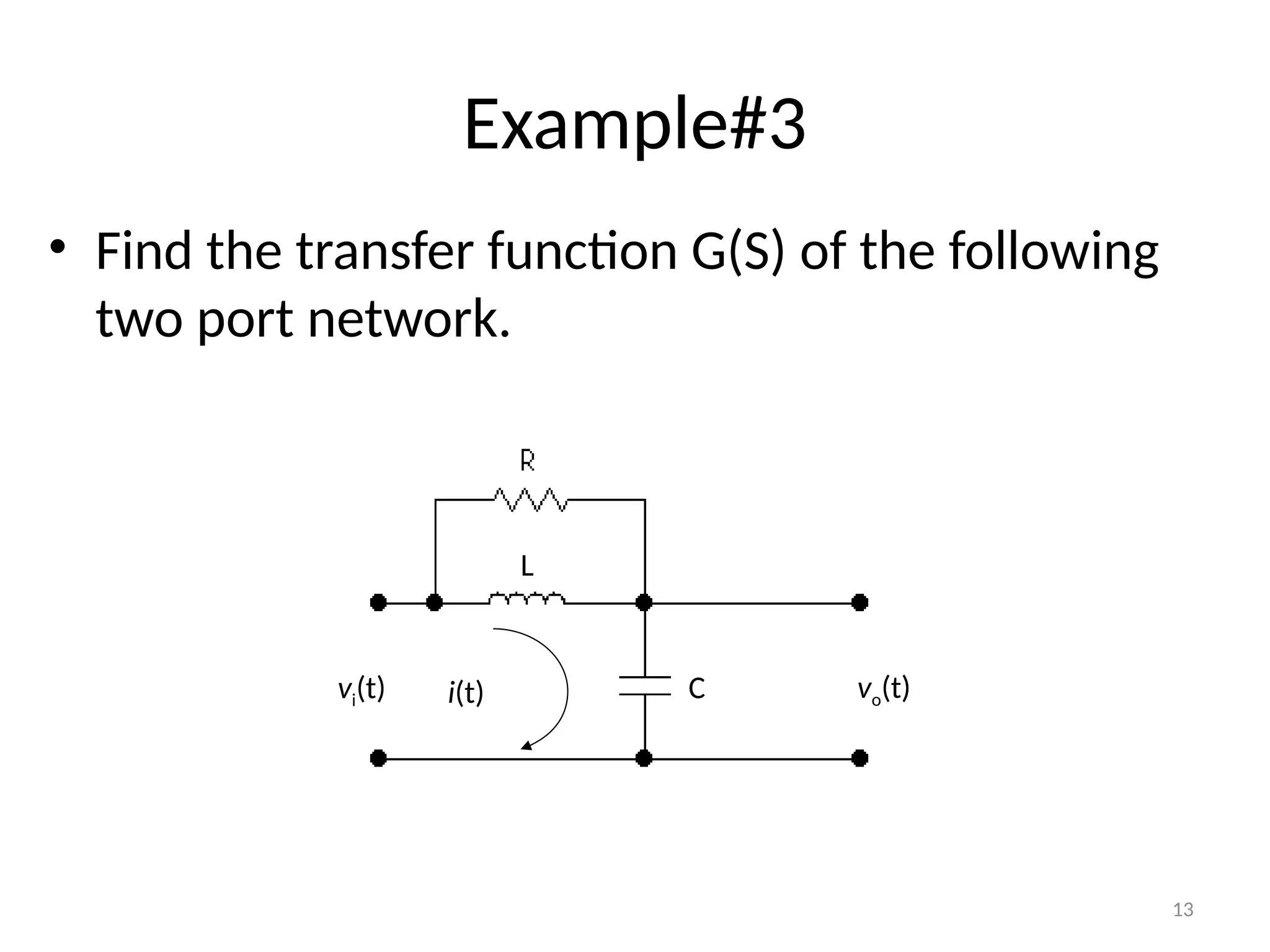
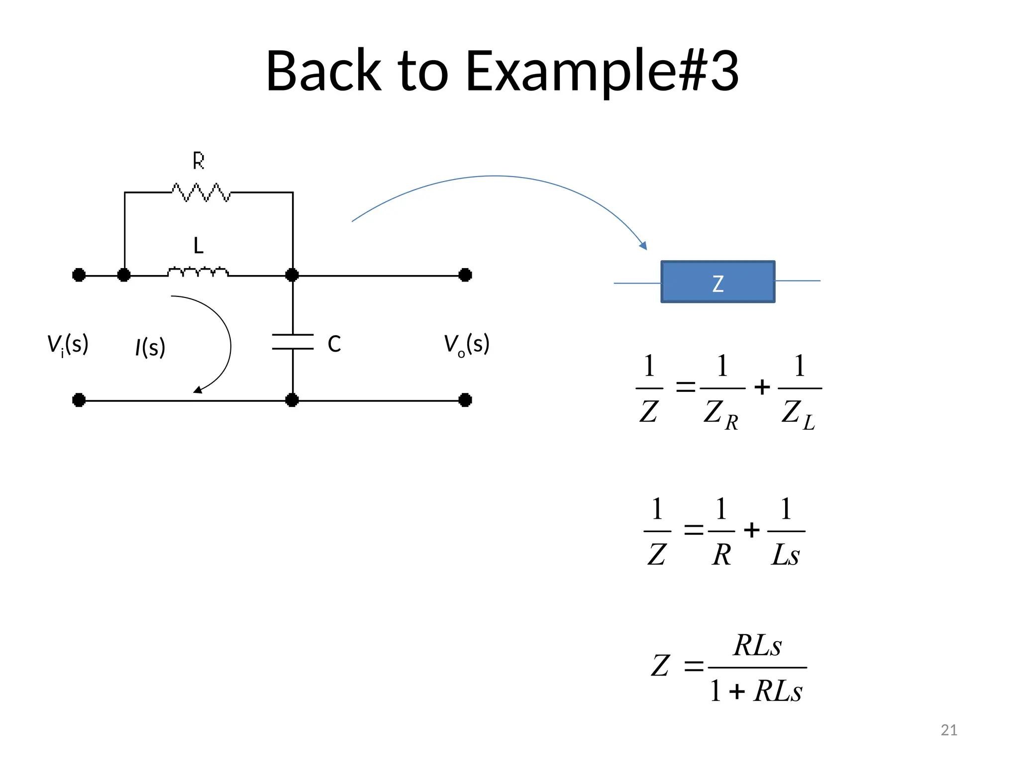
Example#3
• Find thetransfer function G(S) of the following
two port network.
i(t)
vi(t) vo(t)
L
C
14.
14
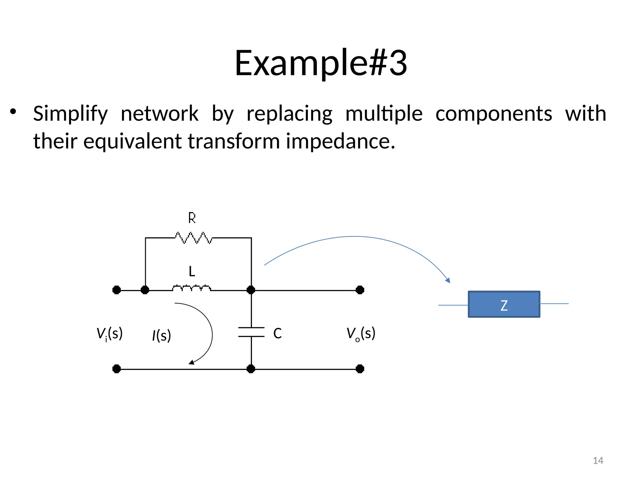
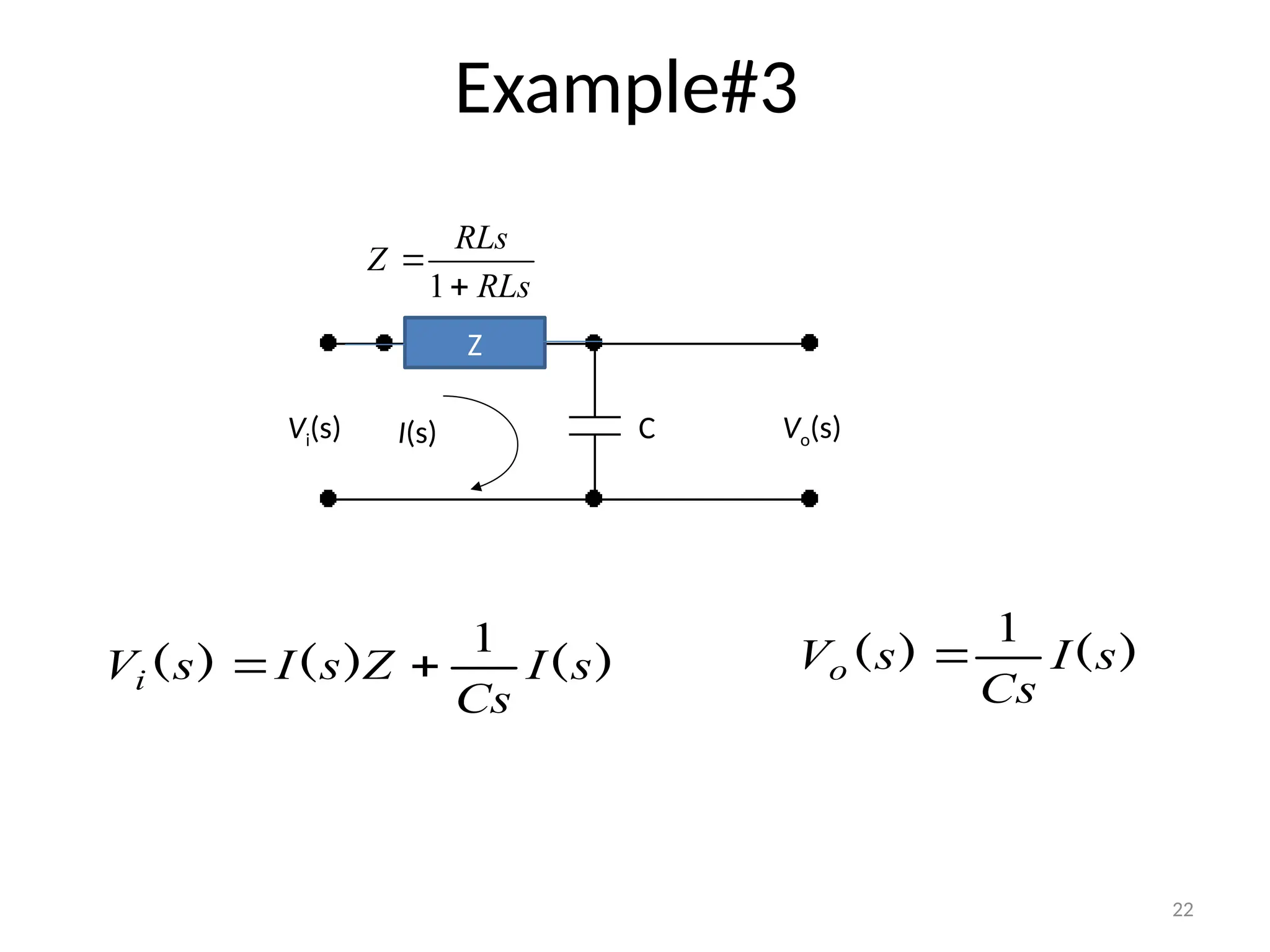
Example#3
• Simplify networkby replacing multiple components with
their equivalent transform impedance.
I(s)
Vi(s) Vo(s)
L
C
Z
18
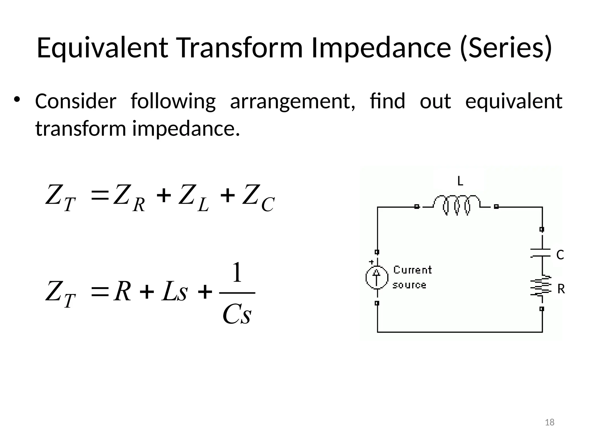
Equivalent Transform Impedance(Series)
• Consider following arrangement, find out equivalent
transform impedance.
L
C
R
C
L
R
T Z
Z
Z
Z
Cs
Ls
R
ZT
1