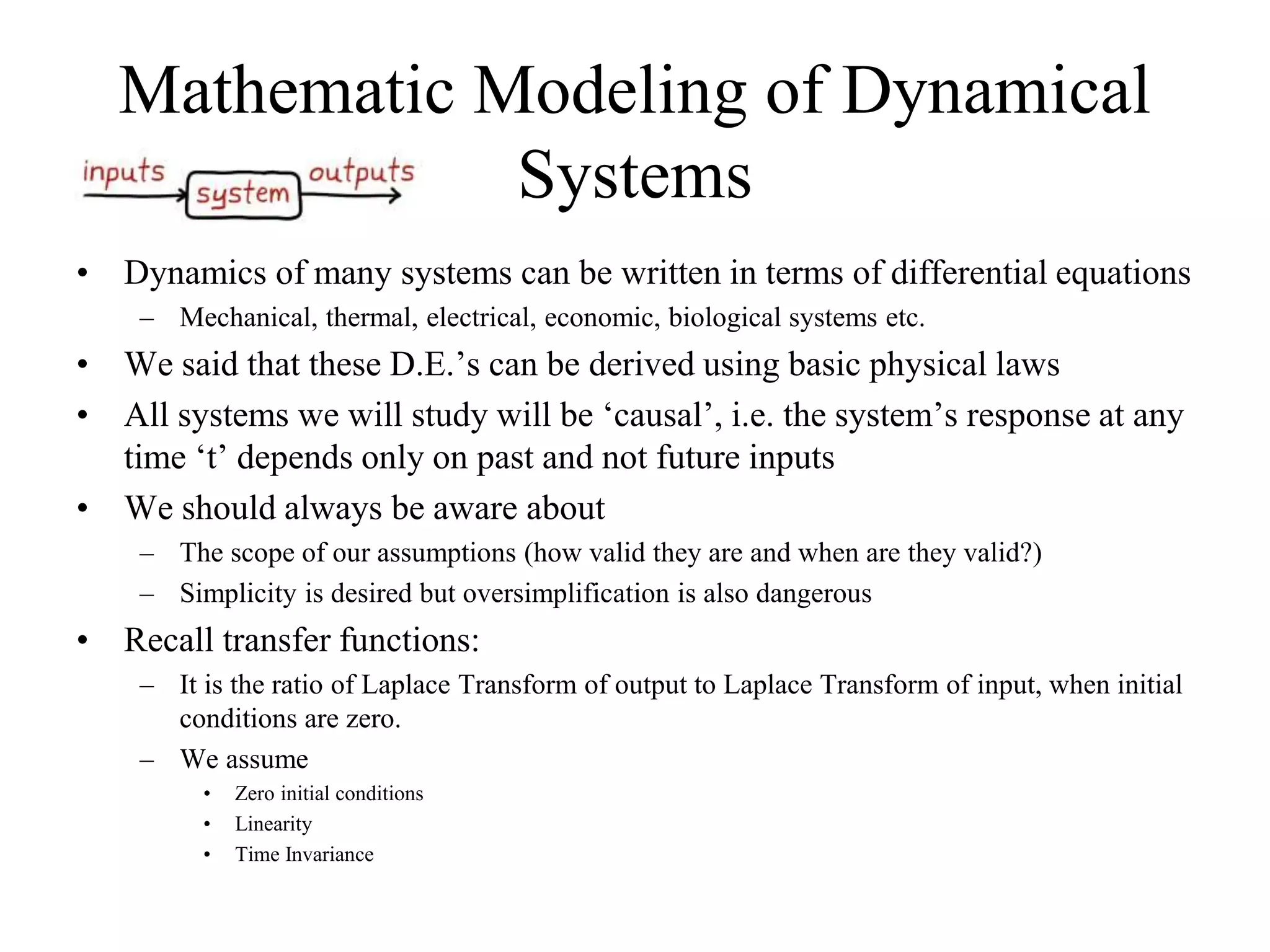
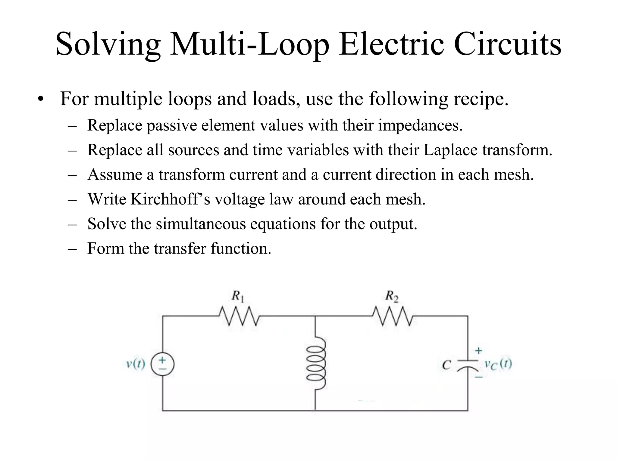
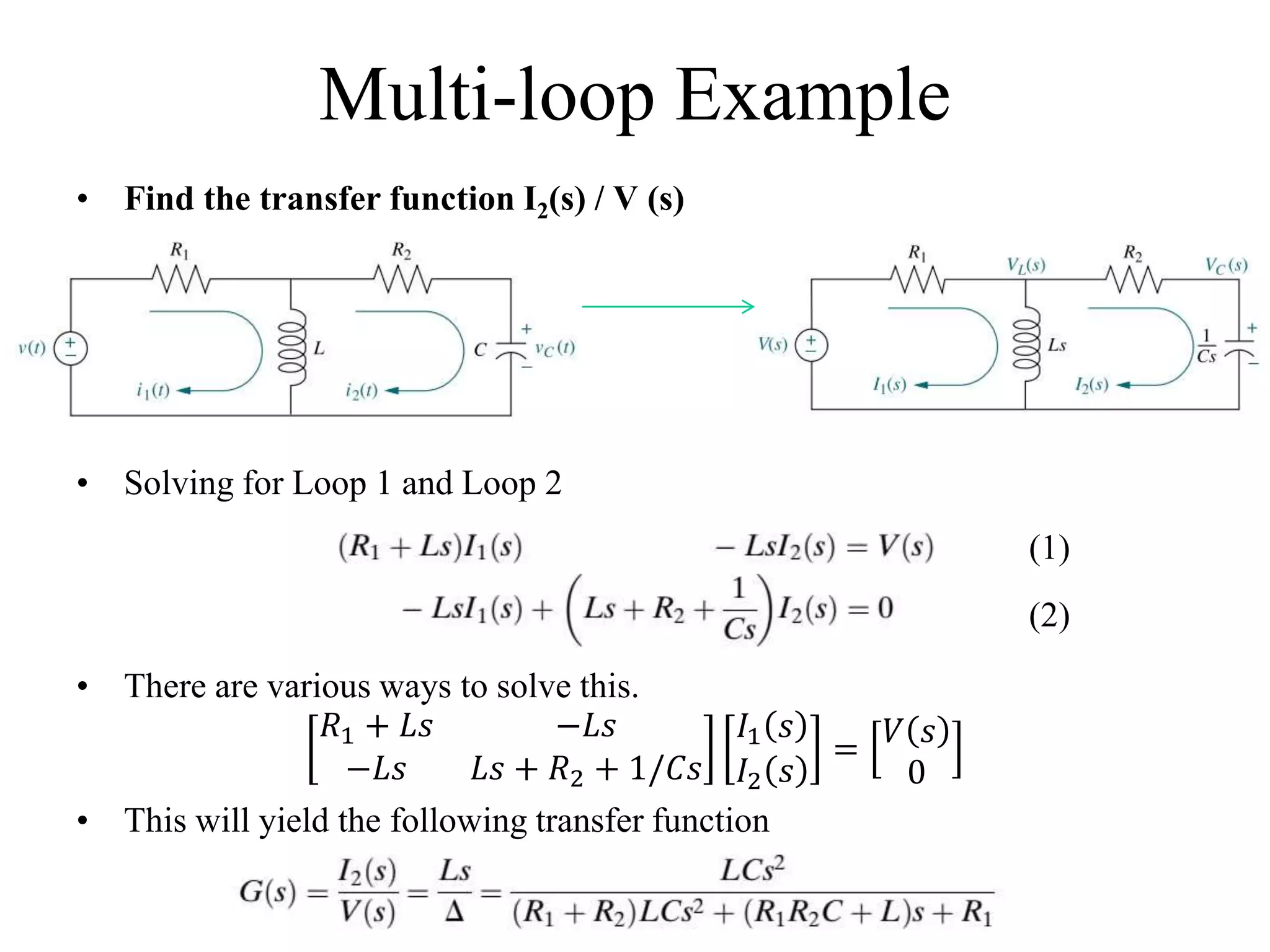
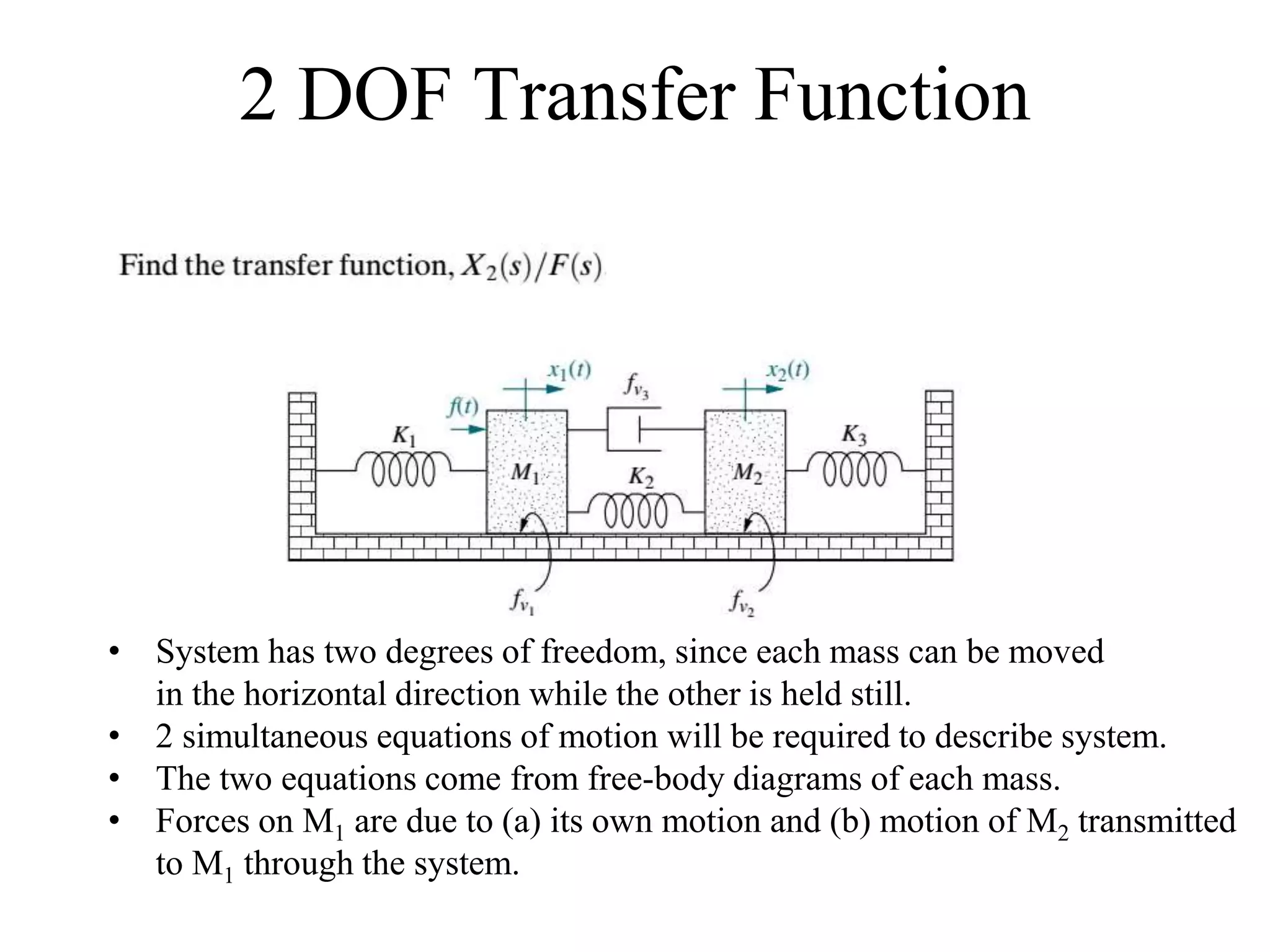
The document discusses the modeling of dynamical systems in control engineering, emphasizing the use of differential equations across various fields such as mechanical and electrical systems. It illustrates the similarities between electrical and mechanical components, including the translation of concepts like impedance and transfer functions. Additionally, it covers the complexities of multi-loop circuits and analogies in mechanical systems, stating that both can be analyzed using similar methods and equations.
![Electrical/Mechanical Analogies
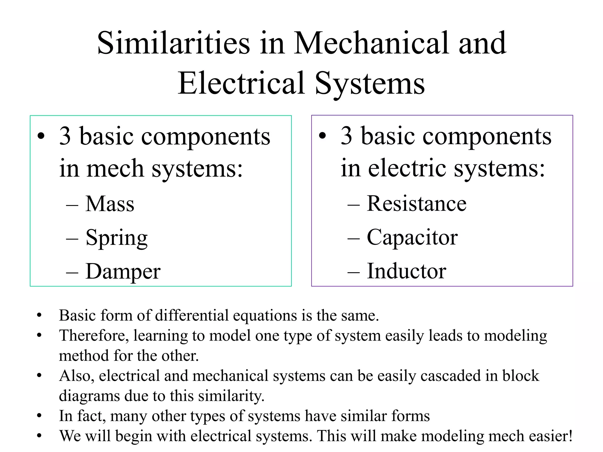
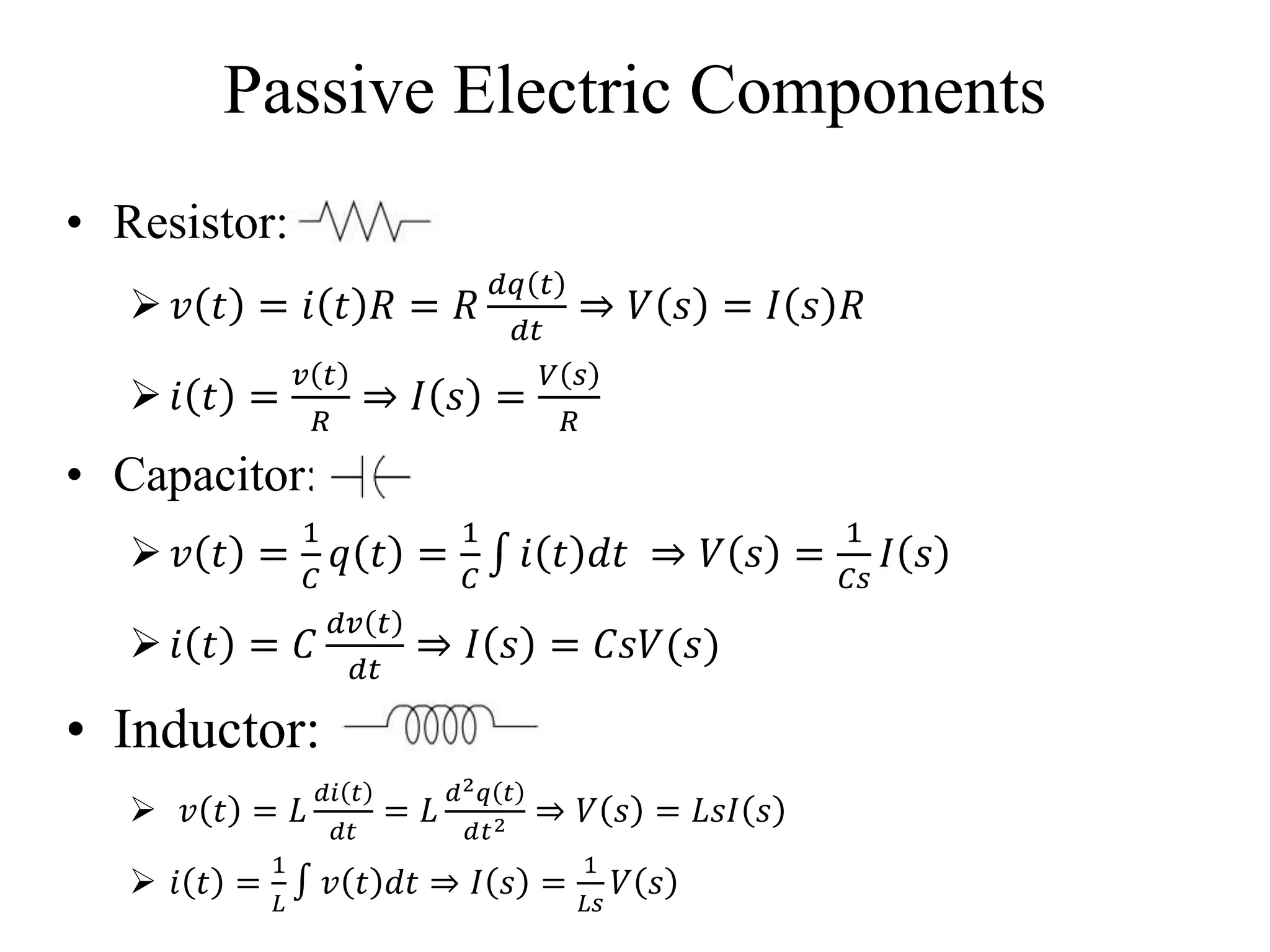
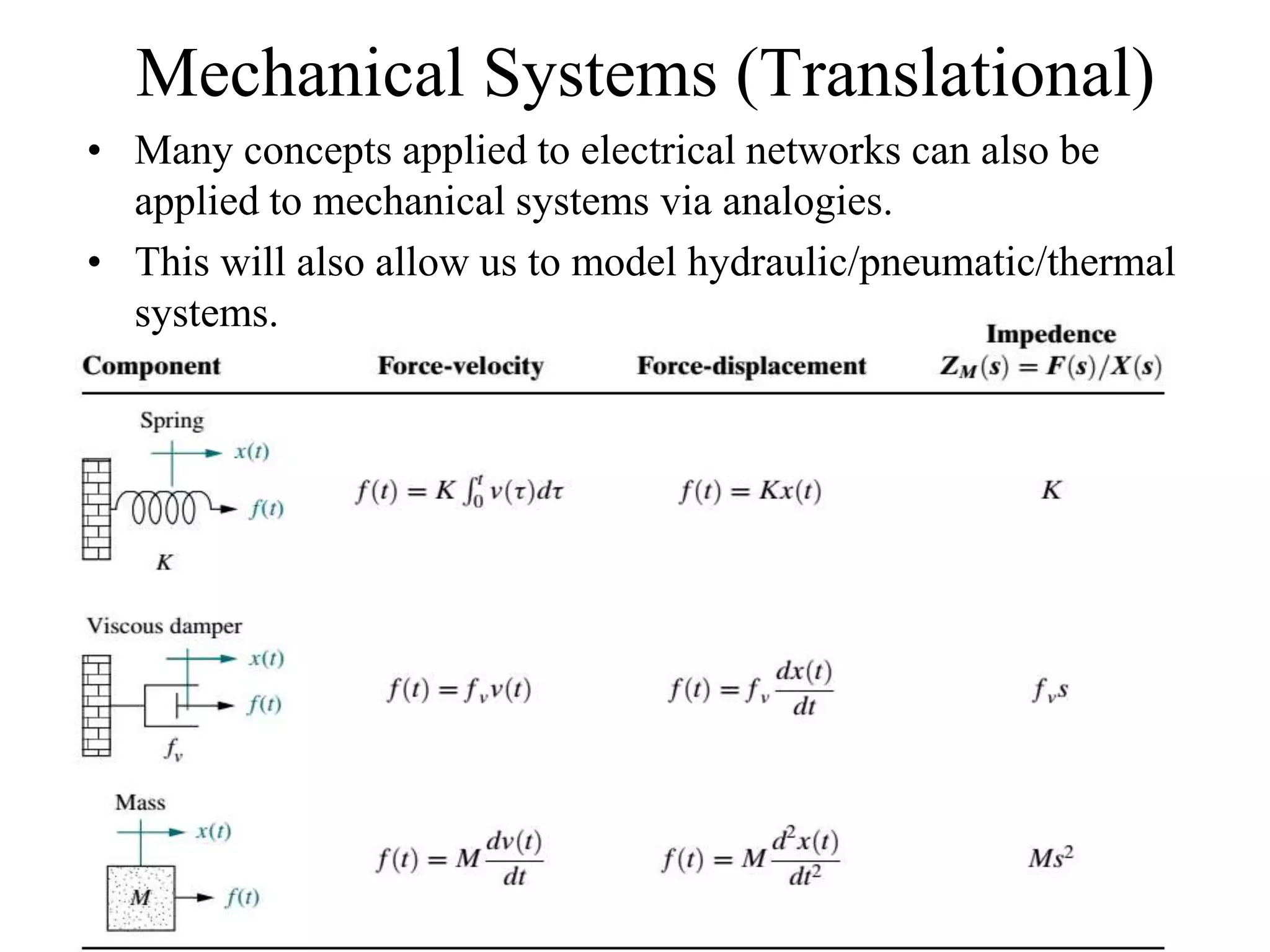
• Mechanical systems, like electrical networks, have 3 passive,
linear components:
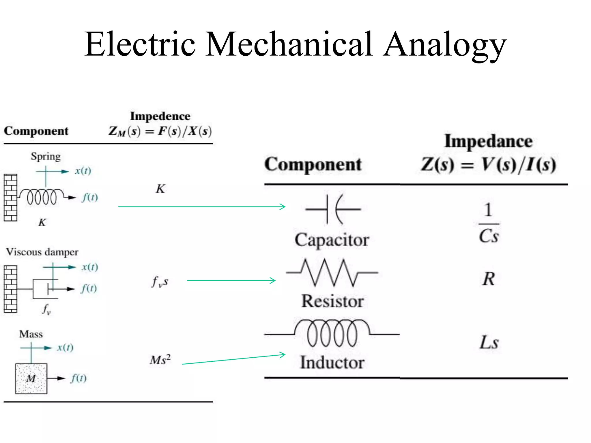
– Two of them (spring and mass) are energy-storage elements; one of
them, the viscous damper, dissipates energy.
– The two energy-storage elements are analogous to the two electrical
energy-storage elements, the inductor and capacitor. The energy
dissipater is analogous to electrical resistance.
• Displacement ‘x’ is analogous to current I
• Force ‘f’ is analogous to voltage ‘v’
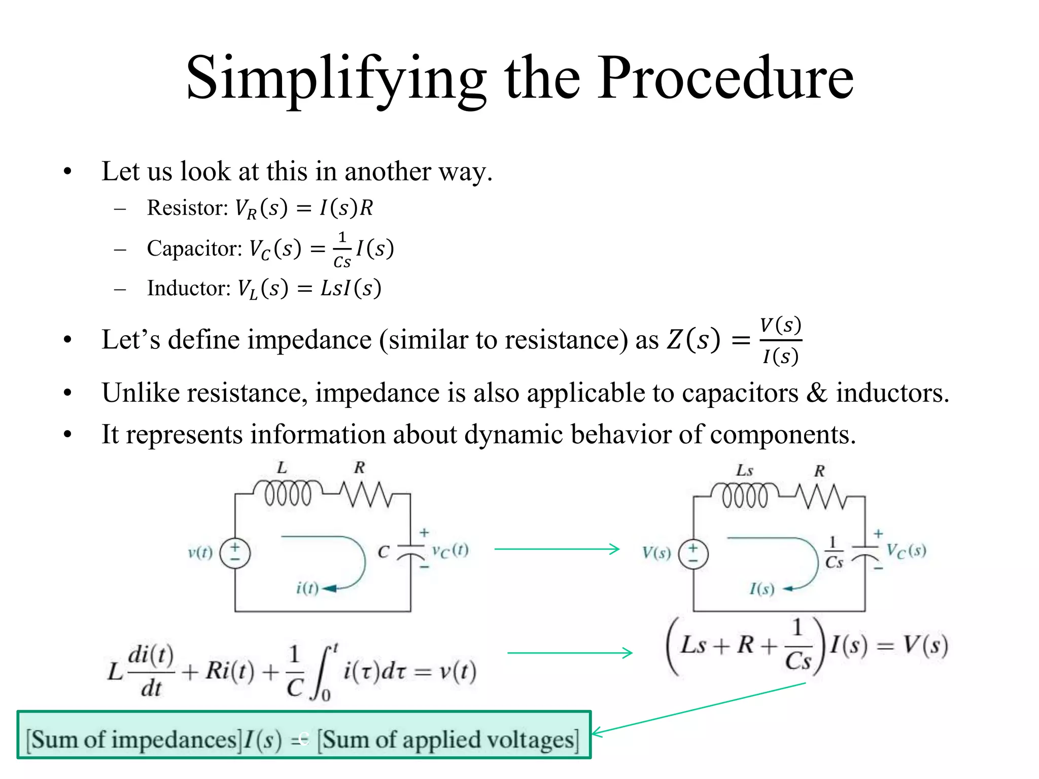
• Impedance (Z=V/I) is therefore Z=F/X
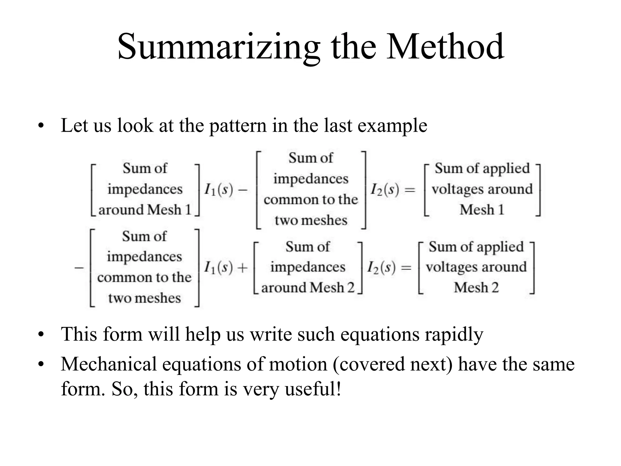
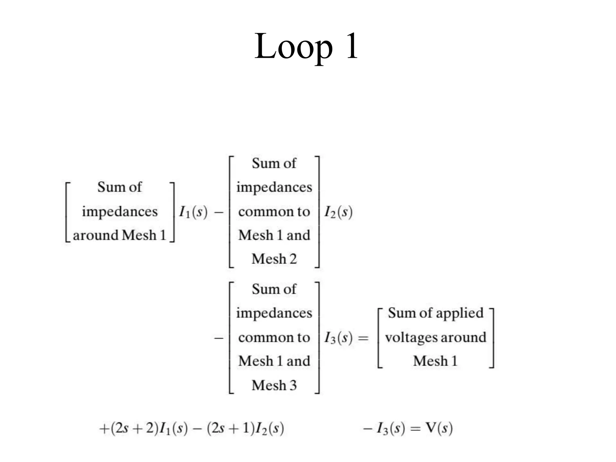
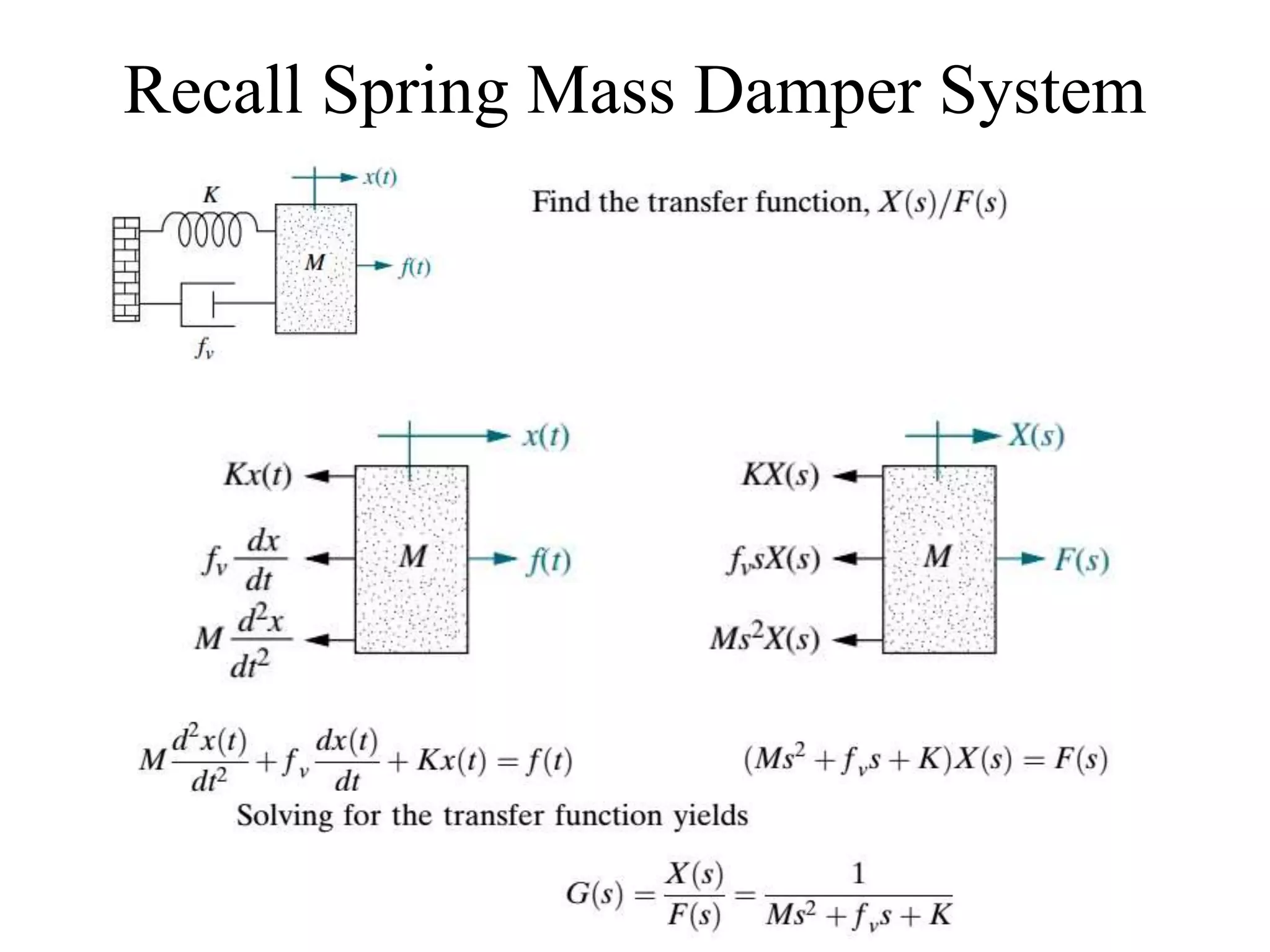
• Since, [Sum of Impedances] I(s) = [Sum of applied voltages]
• Hence, [Sum of Impedances] X(s) = [Sum of applied forces]](https://image.slidesharecdn.com/me314-week03-modeling2-170919164046/75/ME-314-Control-Engineering-Week-03-04-18-2048.jpg)
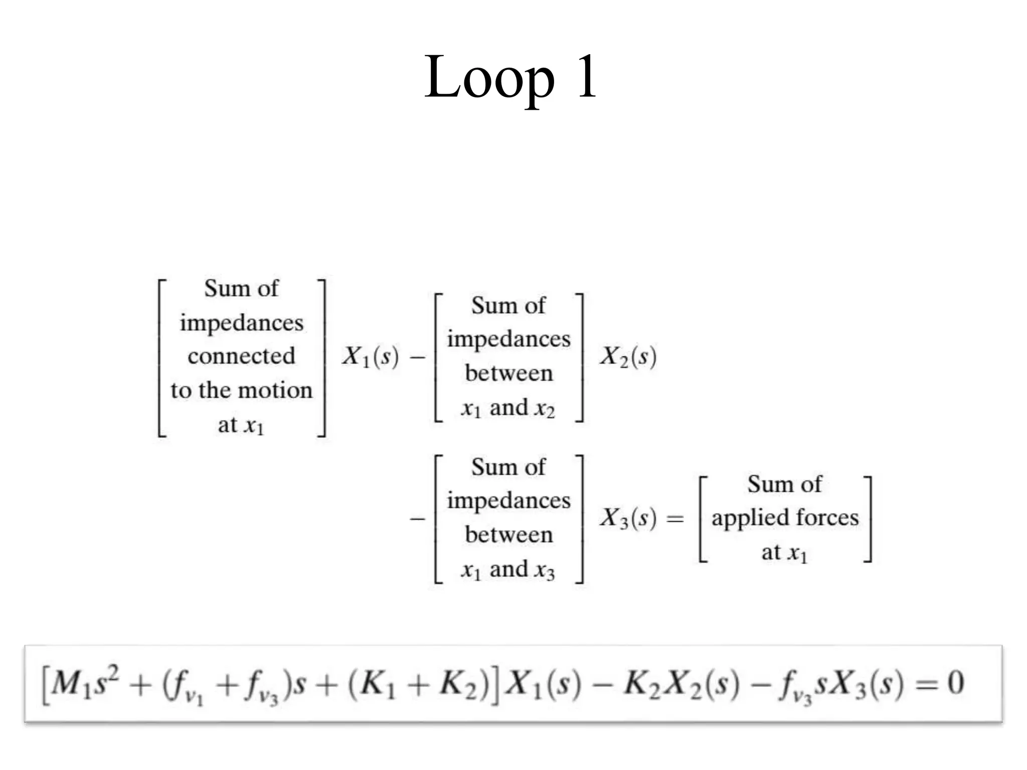
![Use Analogy
[(𝑀1 𝑠2 + 𝑓𝑣1
+ 𝑓𝑣3
𝑠 + (𝐾1+𝐾2)] 𝑋1 𝑠 − (𝐾2+𝑓𝑣3
𝑠)𝑋2 𝑠 = 𝐹 𝑠
−(𝐾2+𝑓𝑣3
𝑠)𝑋1 𝑠 + [(𝑀2 𝑠2
+ 𝑓𝑣2
+ 𝑓𝑣3
𝑠 + (𝐾1+𝐾2)]𝑋2 𝑠 = 0
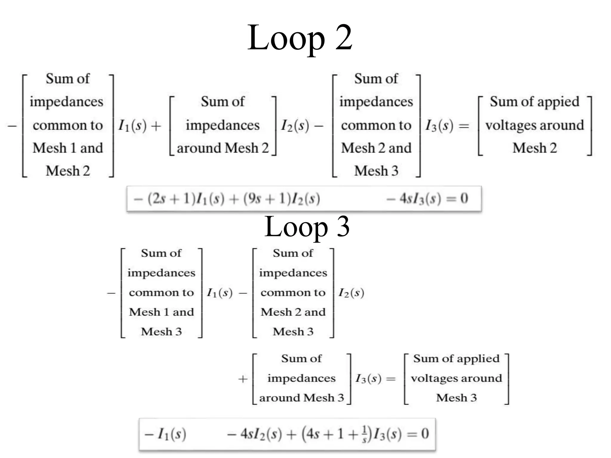
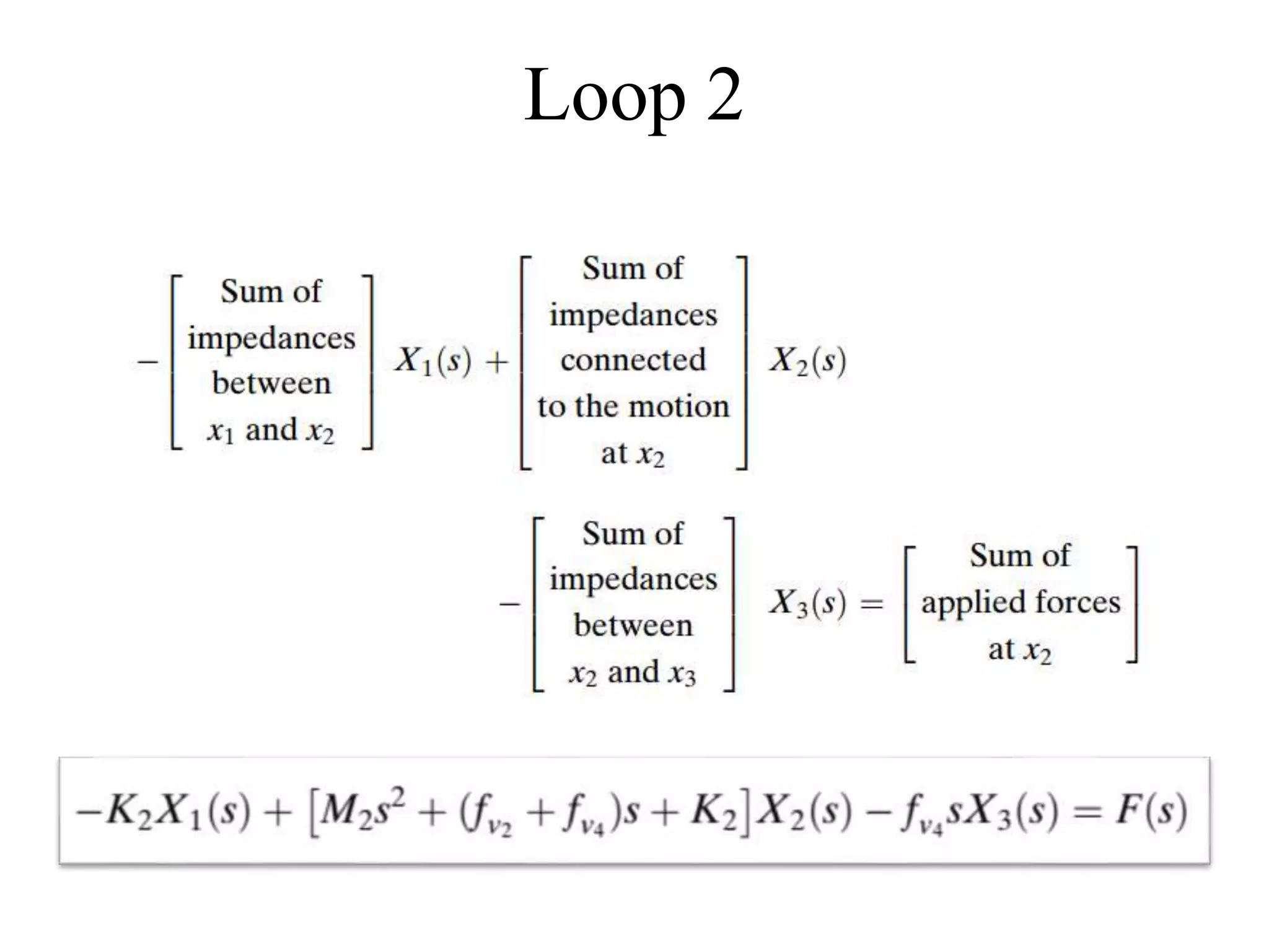
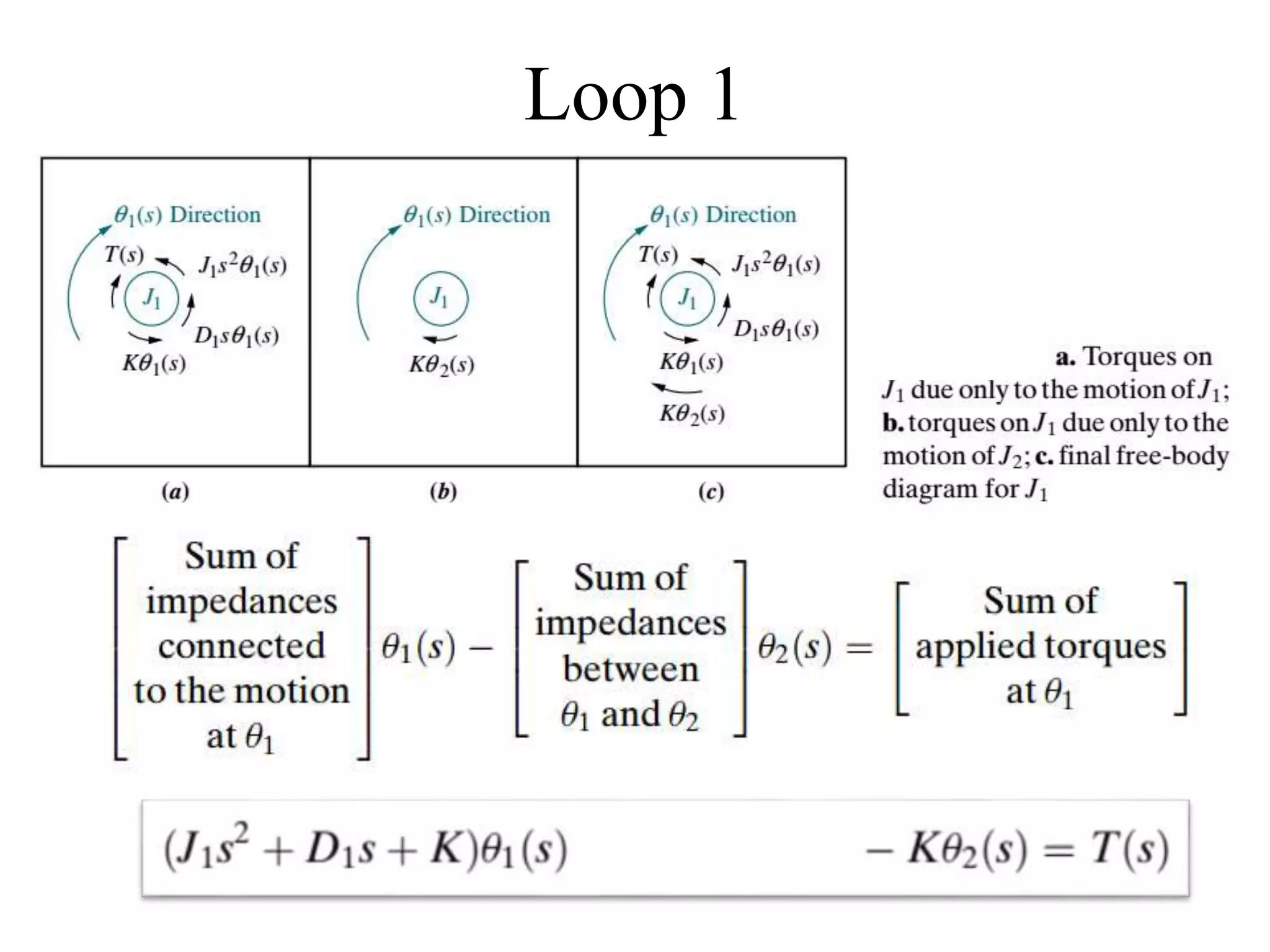
Loop 1
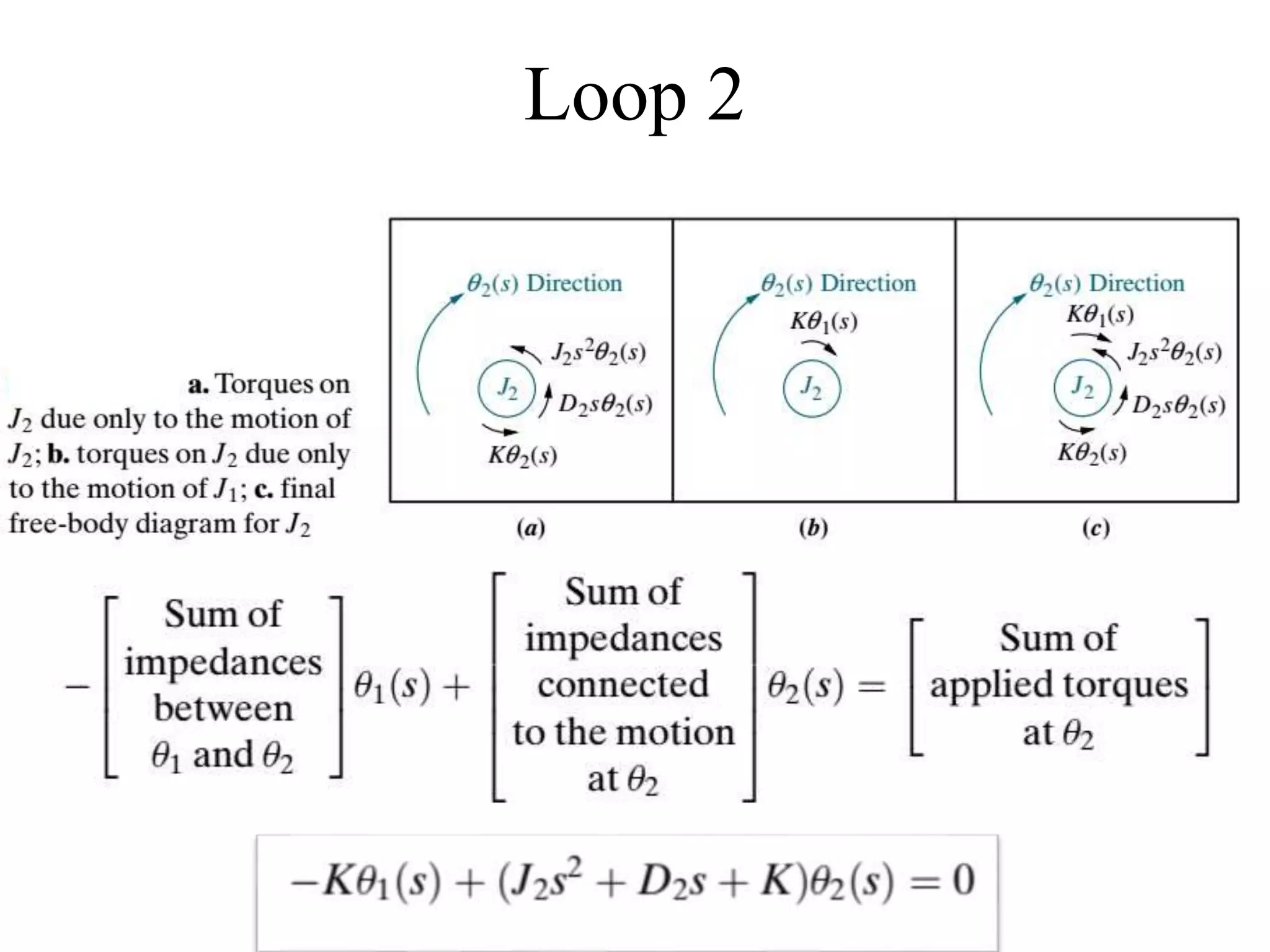
Loop 2](https://image.slidesharecdn.com/me314-week03-modeling2-170919164046/75/ME-314-Control-Engineering-Week-03-04-24-2048.jpg)


![ME 312 Mechanical Machine Design [Screws, Bolts, Nuts]](https://cdn.slidesharecdn.com/ss_thumbnails/me312-dsulec10-screws-170213050612-thumbnail.jpg?width=640&height=640&fit=bounds)
![Av 738- Adaptive Filtering - Wiener Filters[wk 3]](https://cdn.slidesharecdn.com/ss_thumbnails/av-738-aft-spr18-lecture03-optimumfilters-weinerwk3-180215235757-thumbnail.jpg?width=640&height=640&fit=bounds)


![ME 312 Mechanical Machine Design - Introduction [Week 1]](https://cdn.slidesharecdn.com/ss_thumbnails/me312-dsulec01-170213050149-thumbnail.jpg?width=640&height=640&fit=bounds)


