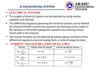
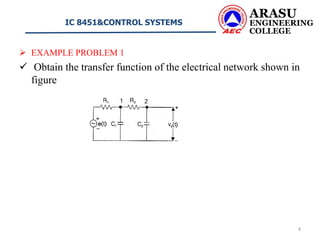
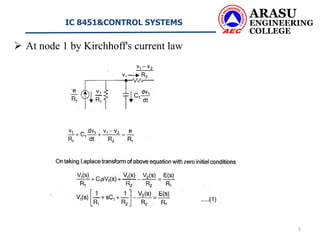
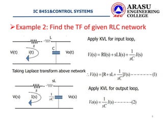
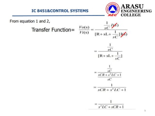
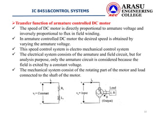
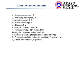
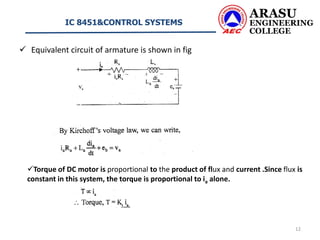
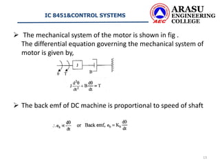
Software Development Life Cycle By Team Orange (Dept. of Pharmacy)
Transfer function of Electrical system
1. IC 8451&CONTROL SYSTEMS
Department of Electrical and Electronics Engineering
Approved by AICTE | Affiliated to Anna University | Accredited by NAAC | Accredited NBA | Recognized by UGC under 2(f) and 12(B)
Chennai Main Road, Kumbakonam- 612 501.
ARASU ENGINEERING COLLEGE
1
3. ARASU
ENGINEERING
COLLEGE
IC 8451&CONTROL SYSTEMS
3
ELECTRICAL SYSTEMS
The models of electrical systems can be obtained by using resistor,
capacitor and inductor.
The differential equations governing the electrical systems can be formed
by writing Kirchhoff's current law equations by choosing various nodes in
the network or Kirchhoff's voltage law equations by choosing various
closed path in the network.
The transfer function can be obtained by taking Laplace transform of the
differential equations and rearranging them as ratio of output to input.
CURRENT VOLTAGE RELATION OF R,LAND C
4. EXAMPLE PROBLEM 1
Obtain the transfer function of the electrical network shown in
figure
ARASU
ENGINEERING
COLLEGE
IC 8451&CONTROL SYSTEMS
4
5. At node 1 by Kirchhoff's current law
ARASU
ENGINEERING
COLLEGE
IC 8451&CONTROL SYSTEMS
5
6. At node 2 by Kirchhoff's current law
ARASU
ENGINEERING
COLLEGE
IC 8451&CONTROL SYSTEMS
6
10. ARASU
ENGINEERING
COLLEGE
IC 8451&CONTROL SYSTEMS
10
Transfer function of armature controlled DC motor
The speed of DC motor is directly proportional to armature voltage and
inversely proportional to flux in field winding.
In armature controlled DC motor the desired speed is obtained by
varying the armature voltage.
This speed control system is electro mechanical control system
The electrical system consists of the armature and field circuit, but for
analysis purpose, only the armature circuit is considered because the
field is exited by a constant voltage.
The mechanical system consist of the rotating part of the motor and load
connected to the shaft of the motor.
11. ARASU
ENGINEERING
COLLEGE
IC 8451&CONTROL SYSTEMS
11
Ra - Armature resistance, Ω
La -Armature inductance, H
ia - Armature current, A
va- Armature voltage, V
eb - Back emf, V
Kt - Torque constant, N-m /A
T - Torque developed by motor, N-m
θ - Angular displacement of shaft, rad
J -Moment of inertia of motor and load,kg-m2 / rad
B - Frictional coefficient of motor and load, N-m/(rad / s)
Kb - Back emf constant, V/(rad / s)
12. Equivalent circuit of armature is shown in fig
ARASU
ENGINEERING
COLLEGE
IC 8451&CONTROL SYSTEMS
12
Torque of DC motor is proportional to the product of flux and current .Since flux is
constant in this system, the torque is proportional to ia alone.
13. The mechanical system of the motor is shown in fig .
The differential equation governing the mechanical system of
motor is given by,
The back emf of DC machine is proportional to speed of shaft
ARASU
ENGINEERING
COLLEGE
IC 8451&CONTROL SYSTEMS
13