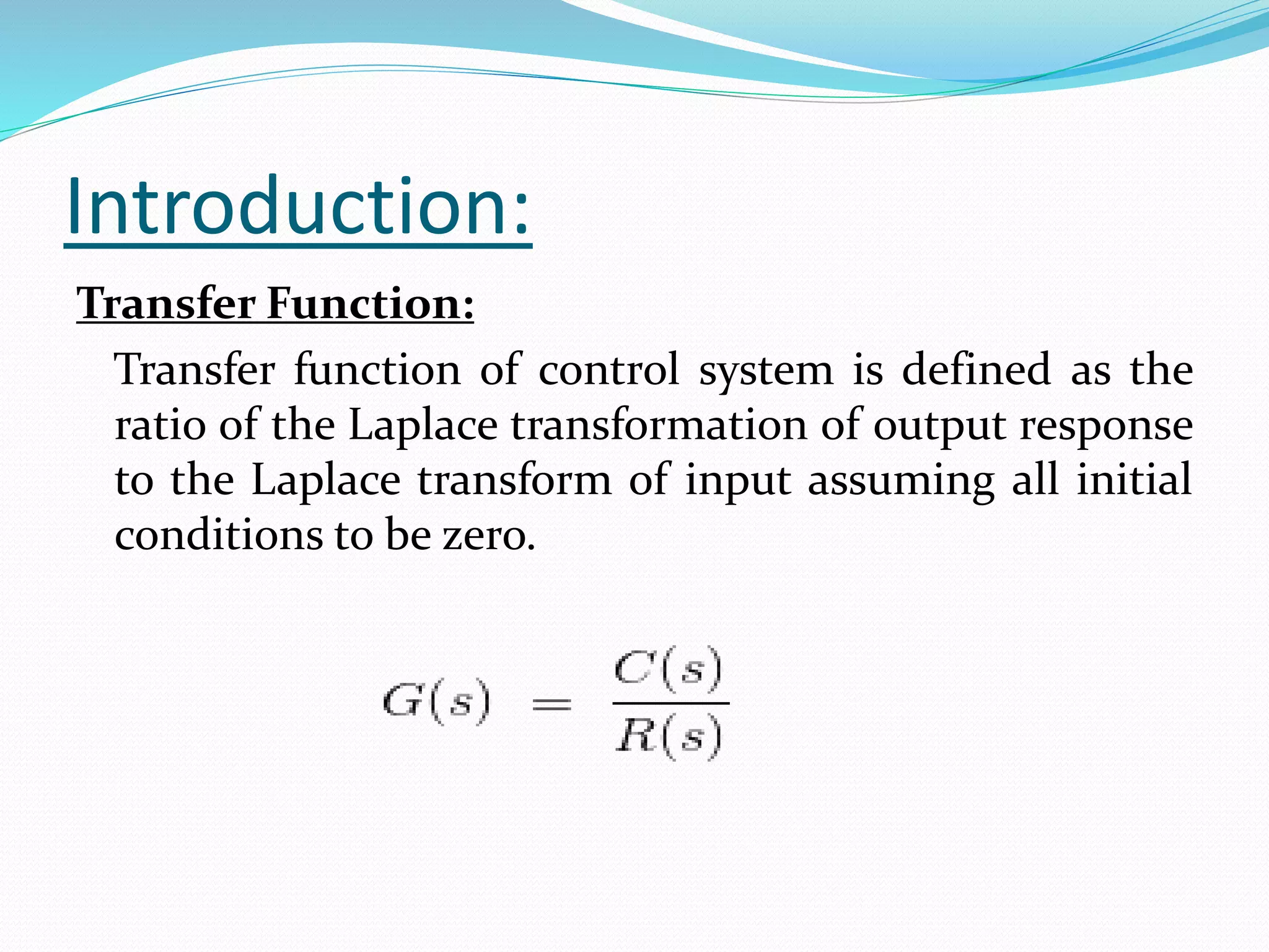
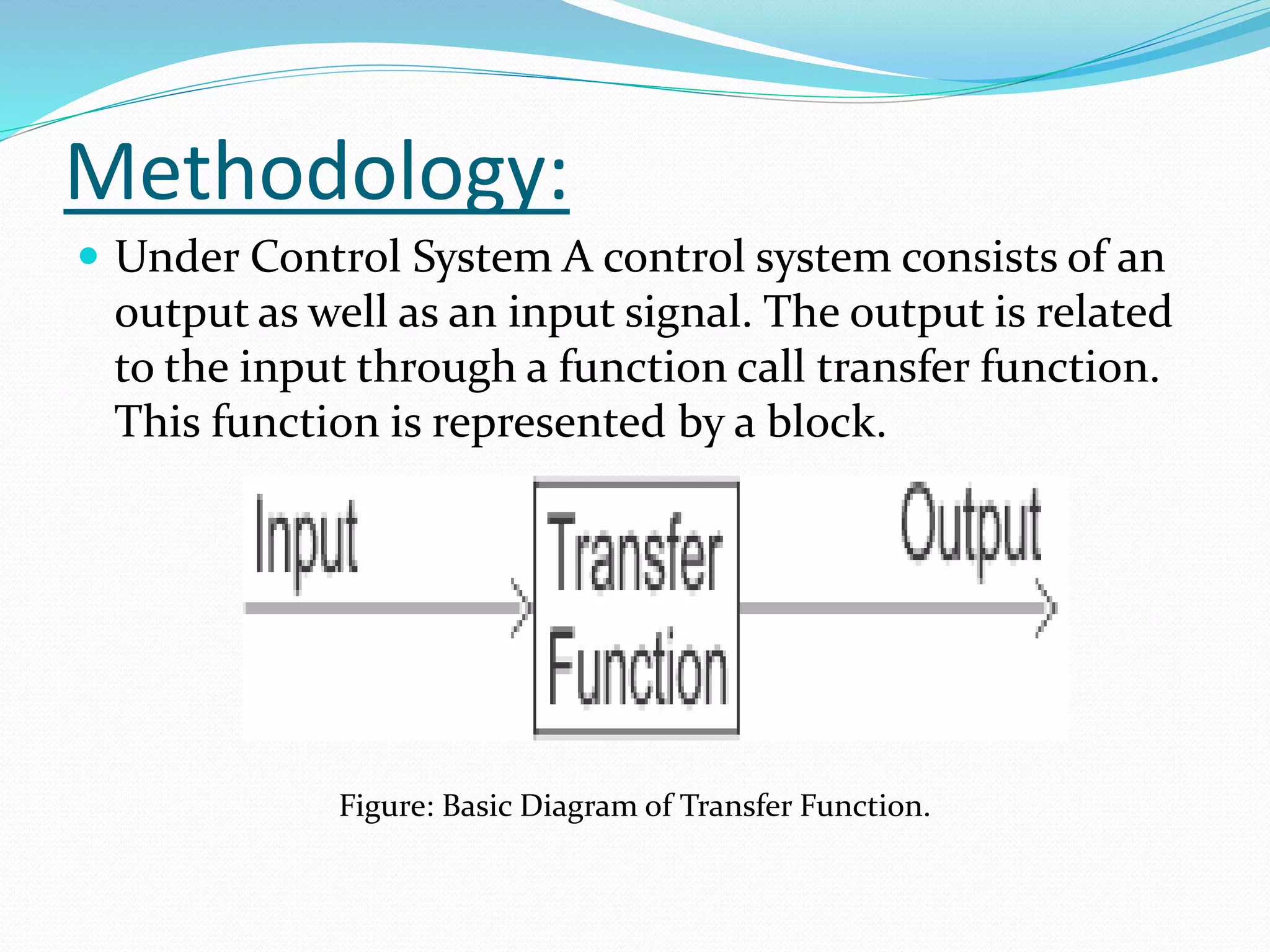
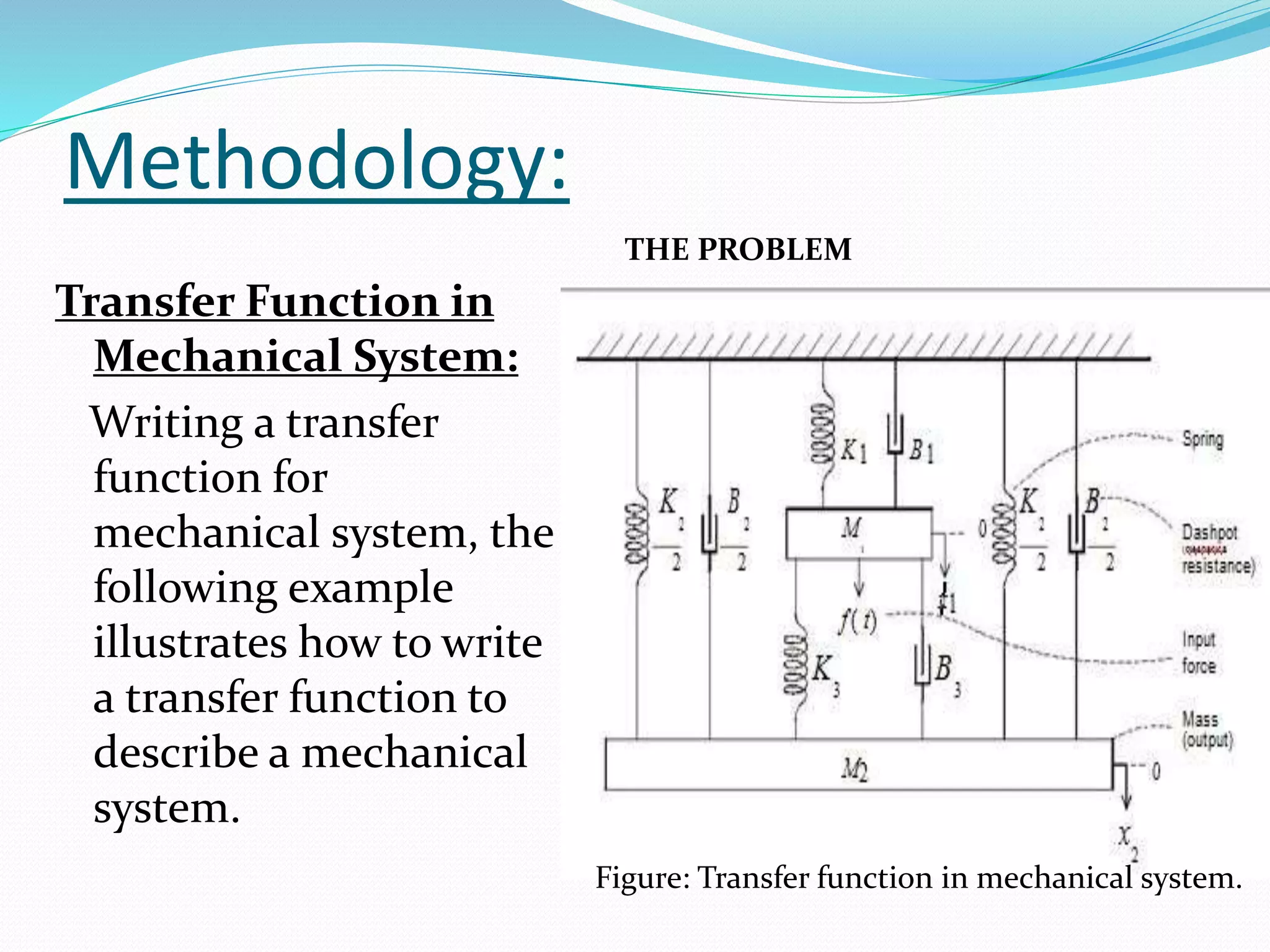
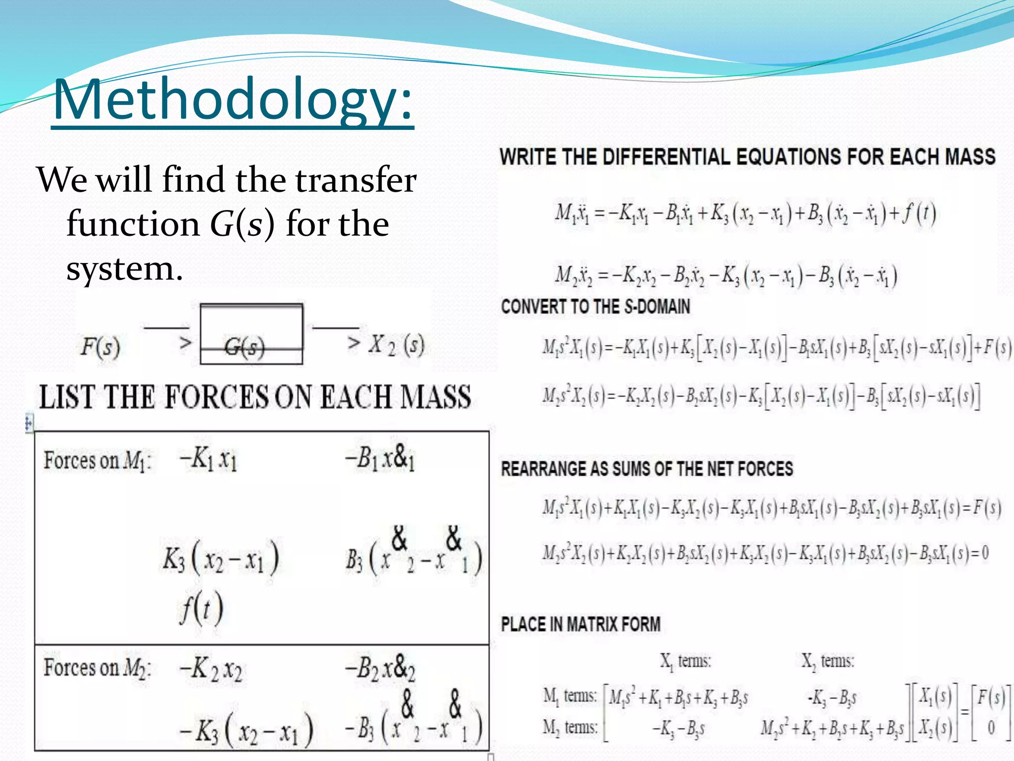
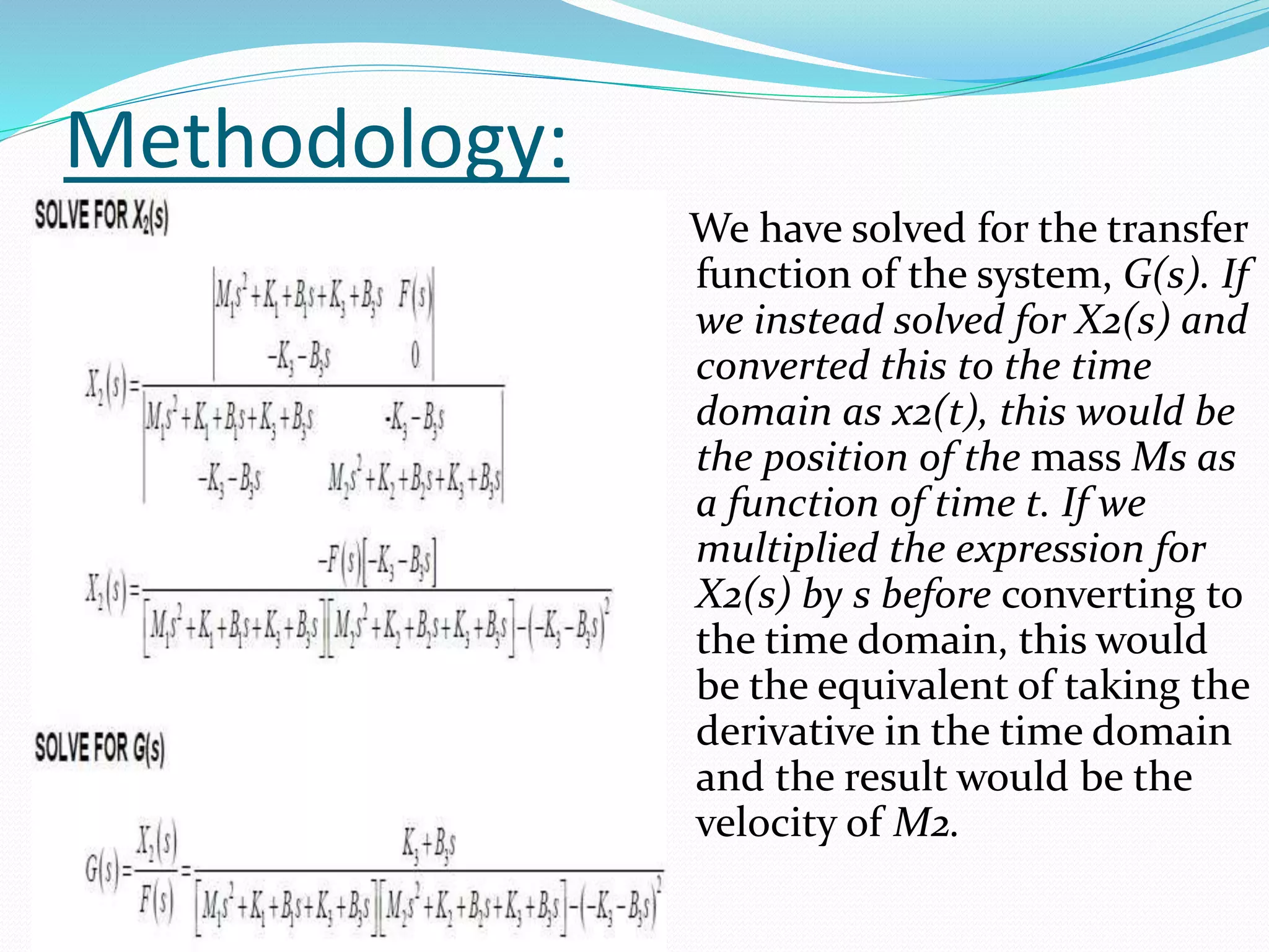
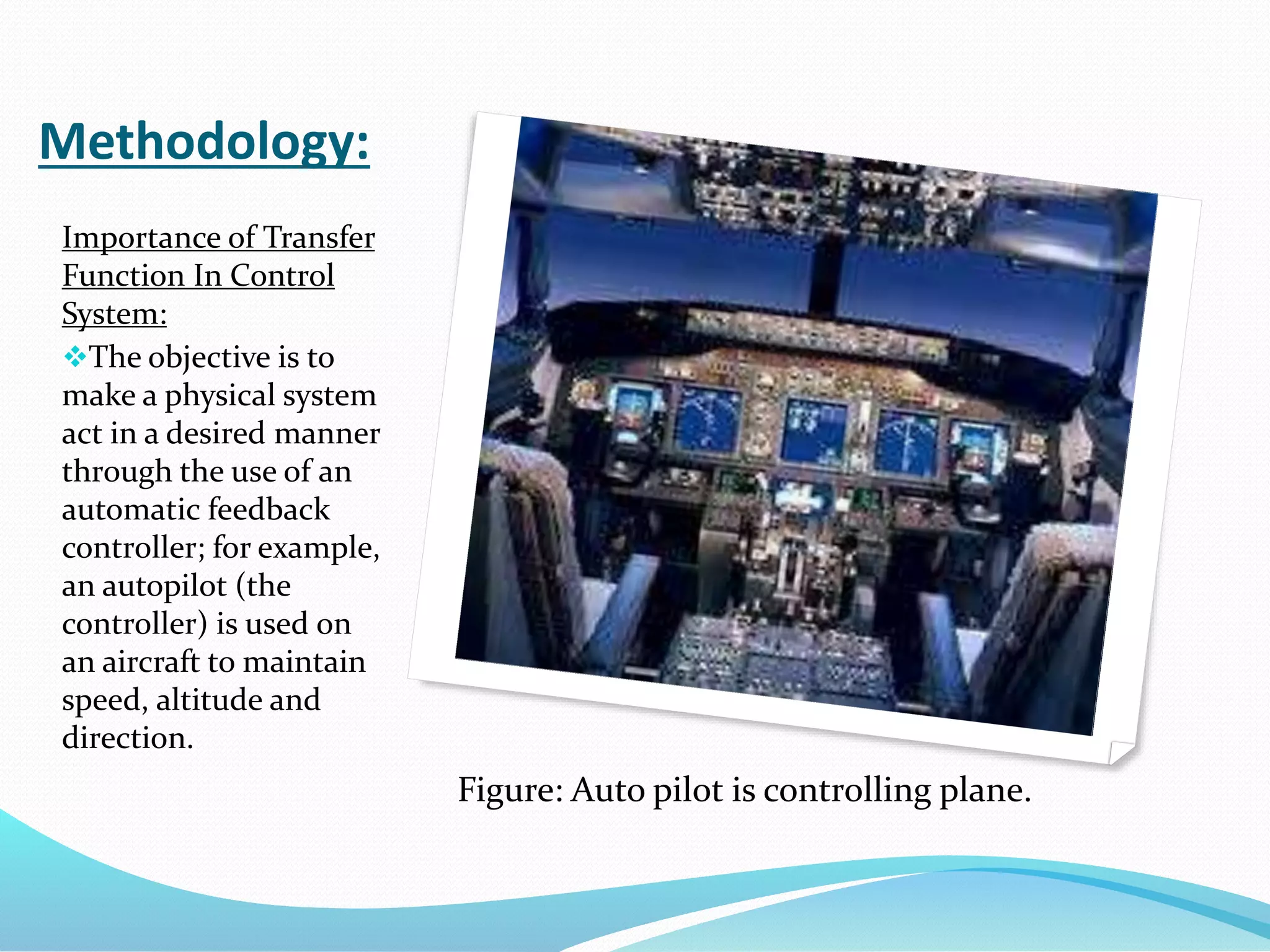
Contents:
1) Introduction.
2) Objectives.
3) Methodology.
4) Discussion.
5) Conclusion.
Introduction:
Transfer Function:
Transfer function of control system is defined as the
ratio of the Laplace transformation of output response
to the Laplace transform of input assuming all initial
conditions to be zero.
Objectives:
 To know about Transfer Function.
 To know about Transfer Function in electrical system.
 To know about Transfer Function in mechanical
system.
 To know about the importance of Transfer Function in
control system.
Methodology:
 Under Control System A control system consists of an
output as well as an input signal. The output is related
to the input through a function call transfer function.
This function is represented by a block.
Figure: Basic Diagram of Transfer Function.
Methodology:
Why input, output and
other signals are
represented in Laplace
form in a control system:
The input and output of a
control system can be
different types.
For mathematical analysis
of a system, all kinds of
signal should be
represented in similar
form.
Figure: Electrical Motor.
Figure: Electrical Generator.
Methodology:
Laplace Transformation:
 Laplace transformation is a technique for solving
differential equations.
 Differential equation of time domain form is first
transformed to algebraic equation of frequency domain
form.
 After solving the algebraic equation in frequency domain,
the result then is finally transformed to time domain form
to achieve the ultimate solution of the differential
equation.
 In other words it can be said that the Laplace
transformation is nothing but a shortcut method of solving
differential equation.
Methodology:
 LTI systems: impulse
response, frequency
response, group delay .
 BIBO stable, Causal,
Passive, Lossless systems.
 Convolution and circular
convolution properties
 Efficient methods for
convolution
◦ single DFT
◦ overlap-add and
overlap-save .
Figure: Linear Time Invariant Systems
Methodology:
Procedure for determining the Transfer Function
of a control system are as follows:
 We form the equations for the system
 Now we take Laplace transform of the system
equations, assuming initial conditions as zero.
 Specify system output and input
 Lastly we take the ratio of the Laplace transform of the
output and the Laplace transform of the input which is
the required transfer function
Methodology:
Transfer Function in Electrical System:
Figure: RL Circuit.
From the circuit, we get,
Now applying Laplace Transform,
we get,
The transfer function of the system, G(s) = I(s)/V(s), the
ratio of output to input.
Methodology:
Example of Transfer Function of a Network:
Figure: Transfer function of a network.
In the above network it is obvious that
Let us assume,
Methodology:
Let us assume,
Taking the Laplace transform of above equations with
considering the initial condition as zero, we get,
Methodology:
Transfer Function in
Mechanical System:
Writing a transfer
function for
mechanical system, the
following example
illustrates how to write
a transfer function to
describe a mechanical
system.
THE PROBLEM
Figure: Transfer function in mechanical system.
Methodology:
We will find the transfer
function G(s) for the
system.
Methodology:
We have solved for the transfer
function of the system, G(s). If
we instead solved for X2(s) and
converted this to the time
domain as x2(t), this would be
the position of the mass Ms as
a function of time t. If we
multiplied the expression for
X2(s) by s before converting to
the time domain, this would
be the equivalent of taking the
derivative in the time domain
and the result would be the
velocity of M2.
Methodology:
Importance of Transfer
Function In Control
System:
The objective is to
make a physical system
act in a desired manner
through the use of an
automatic feedback
controller; for example,
an autopilot (the
controller) is used on
an aircraft to maintain
speed, altitude and
direction.
Figure: Auto pilot is controlling plane.
Methodology:
 Feedback is a
fundamental concept in
engineering, and systems
control harnesses its
power to achieve desired
system behaviors.
 Control systems are found
in abundance in industry,
and include the control of
assembly lines, machine
tools, robotics, aerospace
systems and the process
control widely used in
chemical processing
industry.
Figure: Importance of Transfer function in
Robotics.
Figure: Importance of Transfer function in
Aerospace.
Methodology:
Advantages and Features of Transfer Function:
 Once transfer function is known, output response for
any type of reference input can be calculated.
 Once transfer function is known, output response for
any type of reference input calculated.
 It helps in determining the important information
about the system i.e. poles, zeros, characteristic
equation etc.
 It helps in the stability analysis of the system.
Discussion:
There are few limitations of the transfer function.
Only applicable to linear system.
It does not provide any information concerning the
physical structure of the system.
From transfer function, physical nature of the system
whether it is electrical, mechanical, thermal or
hydraulic, cannot be judged.
Effects arising due to initial conditions are neglected.
Hence initial conditions lose their importance.
Conclusion:
The transfer function was the primary tool used in
classical control engineering. However, it has proven
to be unwieldy for the analysis of multiple-input
multiple-output (MIMO) systems, and has been
largely supplanted by state space representations for
such system. In spite of this, a transfer matrix can be
always obtained for any linear system.
Transfer function, determination of transfer function in mechanical and electrical systems with importance in control system

Transfer function, determination of transfer function in mechanical and electrical systems with importance in control system

  • 2.
    Contents: 1) Introduction. 2) Objectives. 3)Methodology. 4) Discussion. 5) Conclusion.
  • 3.
    Introduction: Transfer Function: Transfer functionof control system is defined as the ratio of the Laplace transformation of output response to the Laplace transform of input assuming all initial conditions to be zero.
  • 4.
    Objectives:  To knowabout Transfer Function.  To know about Transfer Function in electrical system.  To know about Transfer Function in mechanical system.  To know about the importance of Transfer Function in control system.
  • 5.
    Methodology:  Under ControlSystem A control system consists of an output as well as an input signal. The output is related to the input through a function call transfer function. This function is represented by a block. Figure: Basic Diagram of Transfer Function.
  • 6.
    Methodology: Why input, outputand other signals are represented in Laplace form in a control system: The input and output of a control system can be different types. For mathematical analysis of a system, all kinds of signal should be represented in similar form. Figure: Electrical Motor. Figure: Electrical Generator.
  • 7.
    Methodology: Laplace Transformation:  Laplacetransformation is a technique for solving differential equations.  Differential equation of time domain form is first transformed to algebraic equation of frequency domain form.  After solving the algebraic equation in frequency domain, the result then is finally transformed to time domain form to achieve the ultimate solution of the differential equation.  In other words it can be said that the Laplace transformation is nothing but a shortcut method of solving differential equation.
  • 8.
    Methodology:  LTI systems:impulse response, frequency response, group delay .  BIBO stable, Causal, Passive, Lossless systems.  Convolution and circular convolution properties  Efficient methods for convolution ◦ single DFT ◦ overlap-add and overlap-save . Figure: Linear Time Invariant Systems
  • 9.
    Methodology: Procedure for determiningthe Transfer Function of a control system are as follows:  We form the equations for the system  Now we take Laplace transform of the system equations, assuming initial conditions as zero.  Specify system output and input  Lastly we take the ratio of the Laplace transform of the output and the Laplace transform of the input which is the required transfer function
  • 10.
    Methodology: Transfer Function inElectrical System: Figure: RL Circuit. From the circuit, we get, Now applying Laplace Transform, we get, The transfer function of the system, G(s) = I(s)/V(s), the ratio of output to input.
  • 11.
    Methodology: Example of TransferFunction of a Network: Figure: Transfer function of a network. In the above network it is obvious that Let us assume,
  • 12.
    Methodology: Let us assume, Takingthe Laplace transform of above equations with considering the initial condition as zero, we get,
  • 13.
    Methodology: Transfer Function in MechanicalSystem: Writing a transfer function for mechanical system, the following example illustrates how to write a transfer function to describe a mechanical system. THE PROBLEM Figure: Transfer function in mechanical system.
  • 14.
    Methodology: We will findthe transfer function G(s) for the system.
  • 15.
    Methodology: We have solvedfor the transfer function of the system, G(s). If we instead solved for X2(s) and converted this to the time domain as x2(t), this would be the position of the mass Ms as a function of time t. If we multiplied the expression for X2(s) by s before converting to the time domain, this would be the equivalent of taking the derivative in the time domain and the result would be the velocity of M2.
  • 16.
    Methodology: Importance of Transfer FunctionIn Control System: The objective is to make a physical system act in a desired manner through the use of an automatic feedback controller; for example, an autopilot (the controller) is used on an aircraft to maintain speed, altitude and direction. Figure: Auto pilot is controlling plane.
  • 17.
    Methodology:  Feedback isa fundamental concept in engineering, and systems control harnesses its power to achieve desired system behaviors.  Control systems are found in abundance in industry, and include the control of assembly lines, machine tools, robotics, aerospace systems and the process control widely used in chemical processing industry. Figure: Importance of Transfer function in Robotics. Figure: Importance of Transfer function in Aerospace.
  • 18.
    Methodology: Advantages and Featuresof Transfer Function:  Once transfer function is known, output response for any type of reference input can be calculated.  Once transfer function is known, output response for any type of reference input calculated.  It helps in determining the important information about the system i.e. poles, zeros, characteristic equation etc.  It helps in the stability analysis of the system.
  • 19.
    Discussion: There are fewlimitations of the transfer function. Only applicable to linear system. It does not provide any information concerning the physical structure of the system. From transfer function, physical nature of the system whether it is electrical, mechanical, thermal or hydraulic, cannot be judged. Effects arising due to initial conditions are neglected. Hence initial conditions lose their importance.
  • 20.
    Conclusion: The transfer functionwas the primary tool used in classical control engineering. However, it has proven to be unwieldy for the analysis of multiple-input multiple-output (MIMO) systems, and has been largely supplanted by state space representations for such system. In spite of this, a transfer matrix can be always obtained for any linear system.