Download to read offline
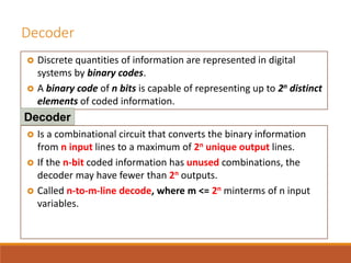
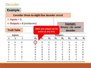
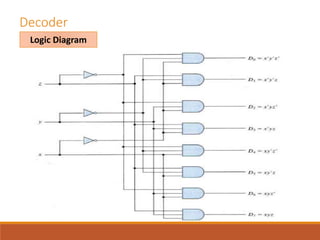
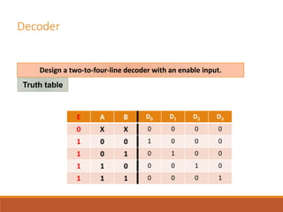
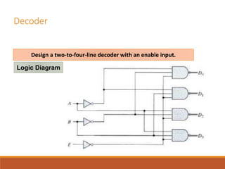
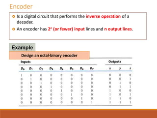
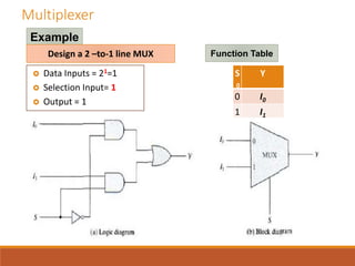
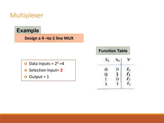
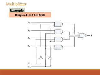
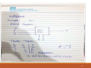
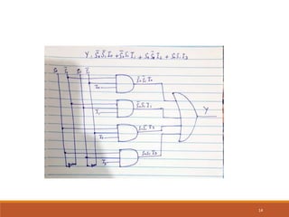

This document discusses decoders, encoders, and multiplexers. It provides examples of a 3-input, 8-output decoder, a 2-input, 4-output decoder with an enable, an octal-binary encoder, and a 4-input, 1-output multiplexer. It also briefly describes magnitude comparators.