Downloaded 1,063 times

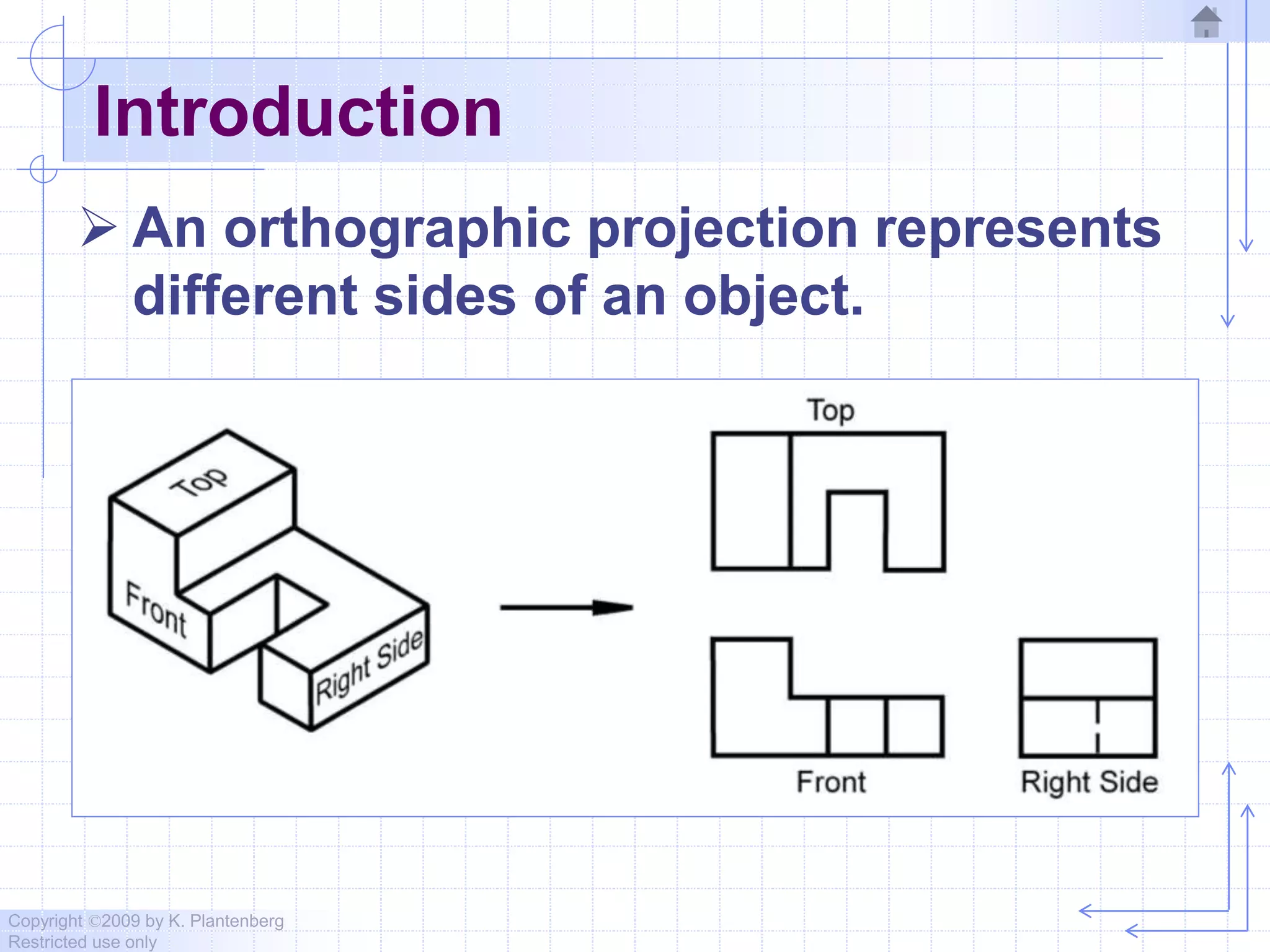
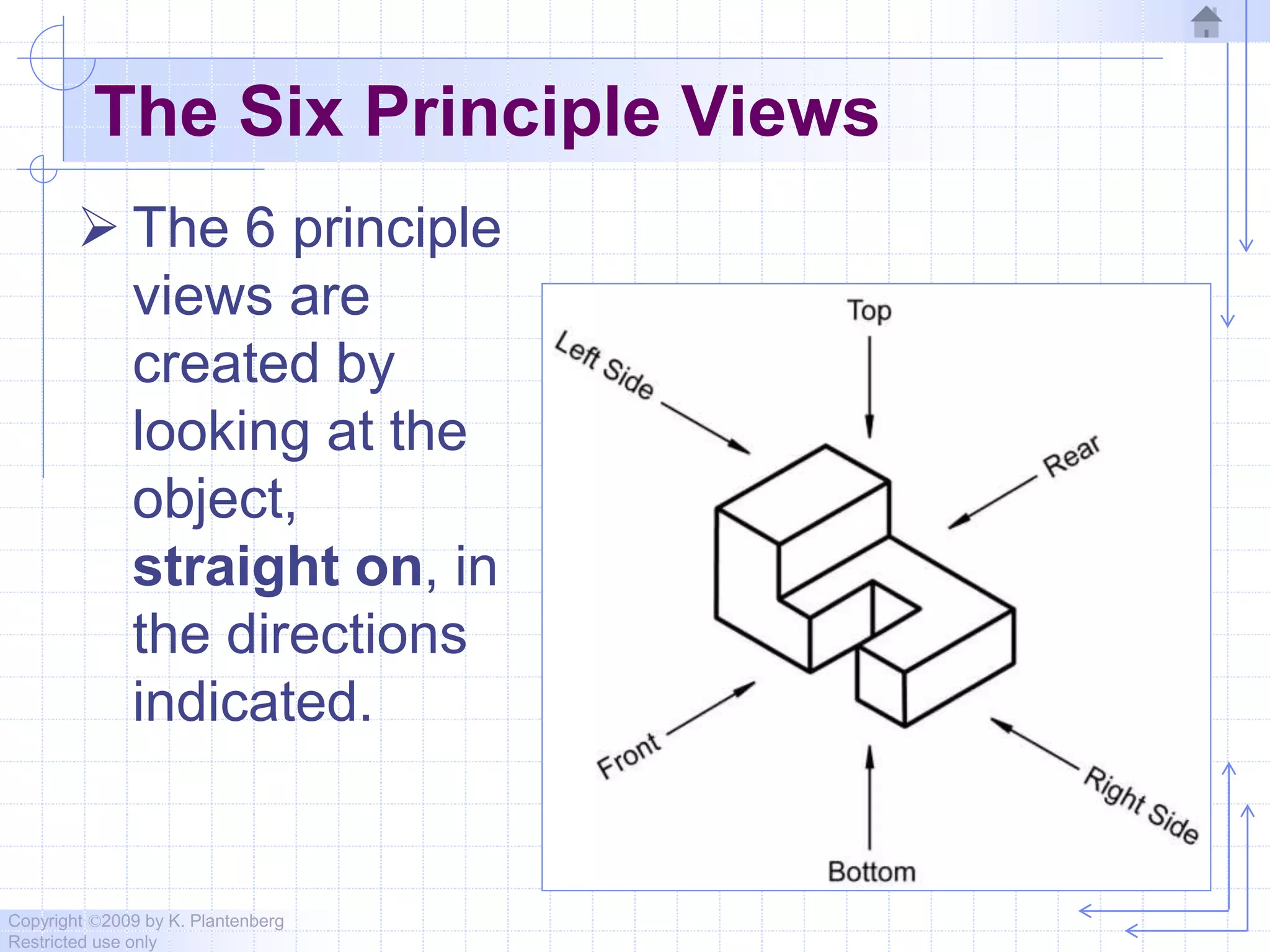
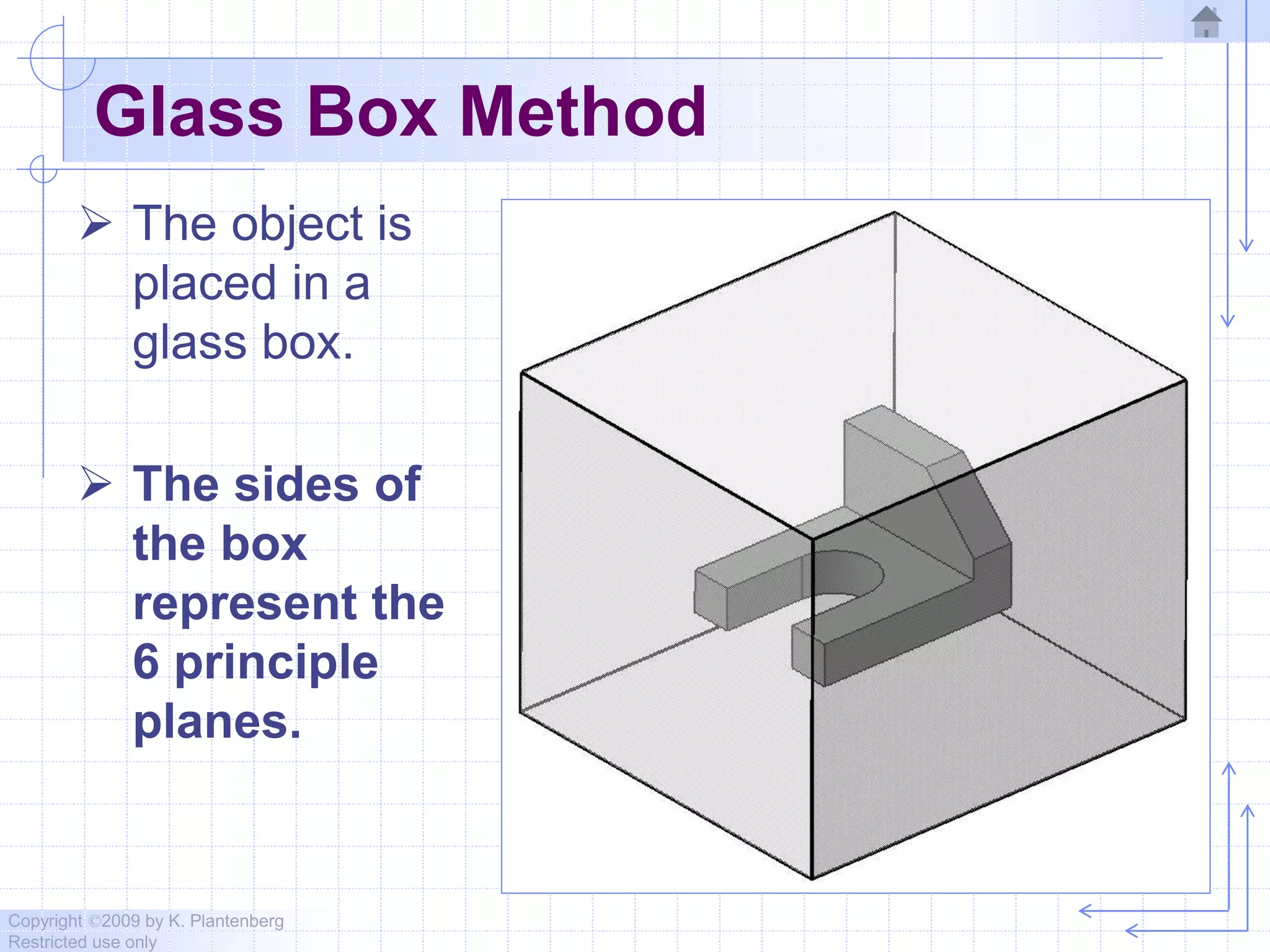
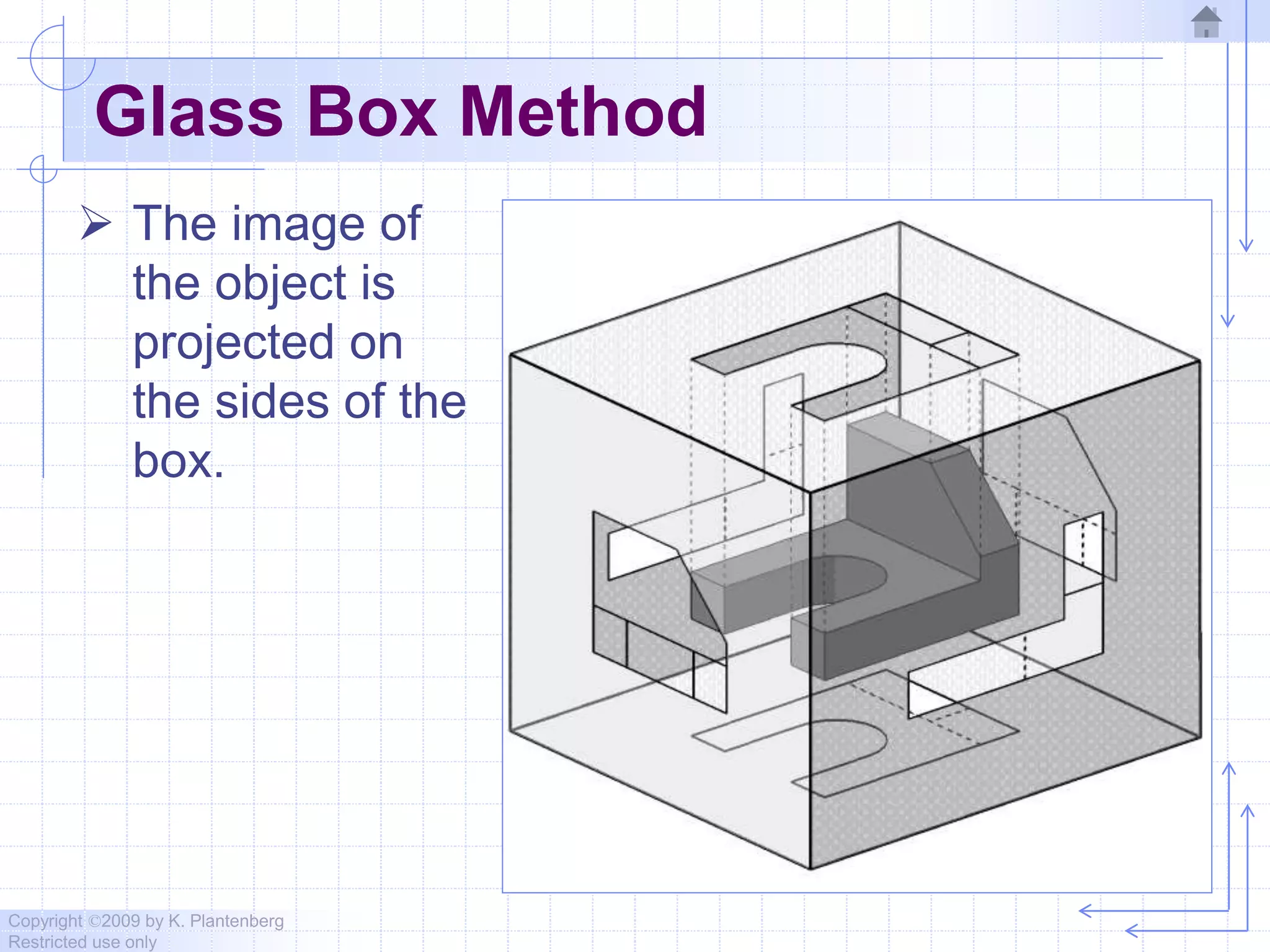
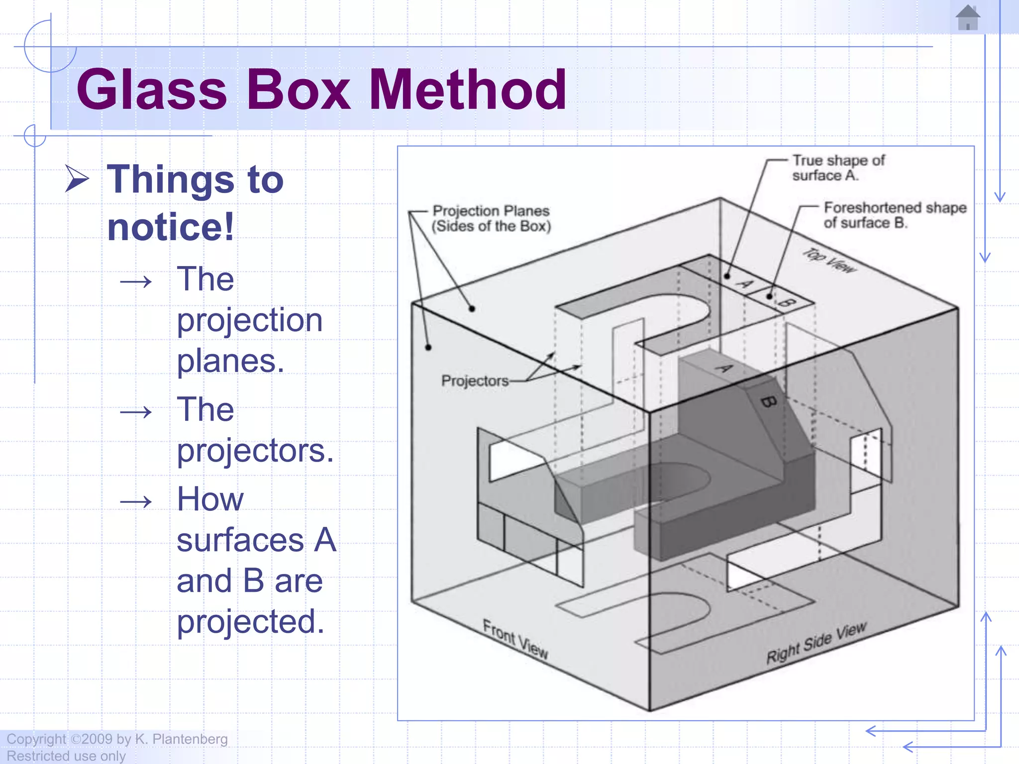
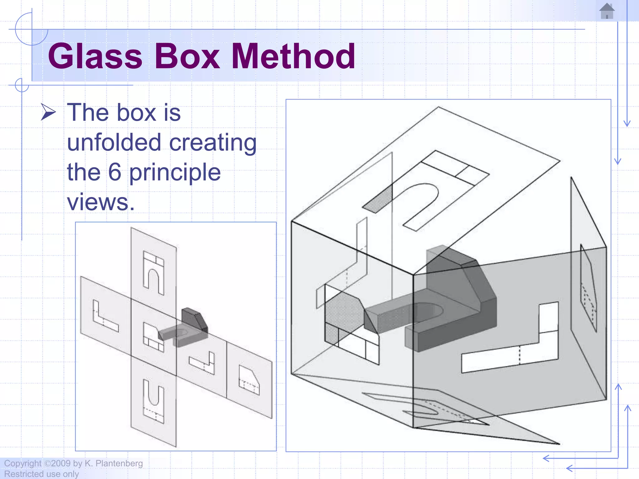
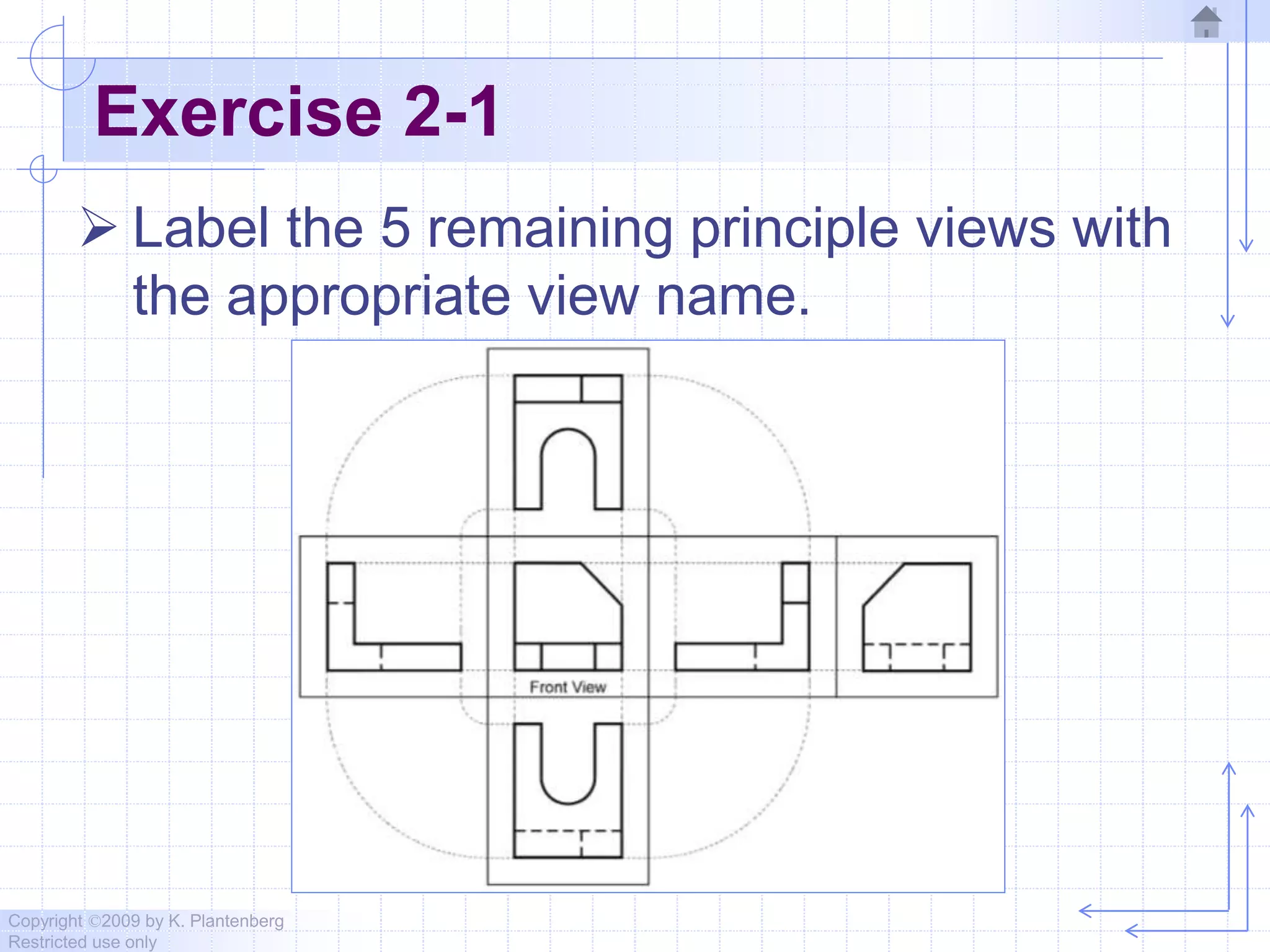
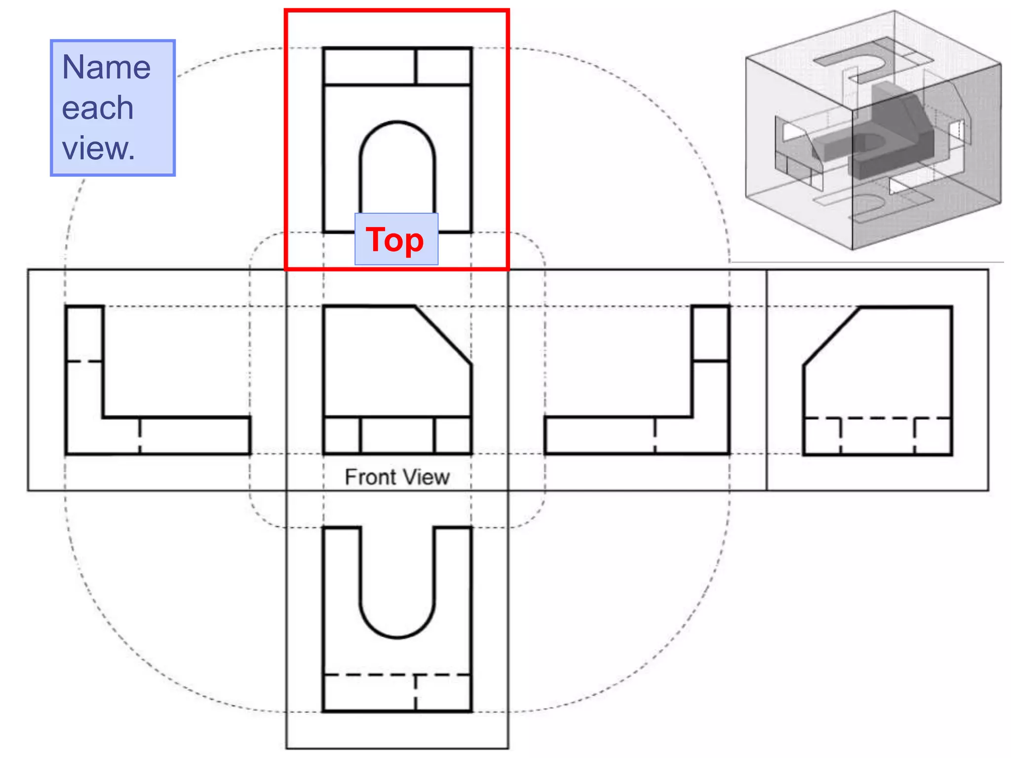
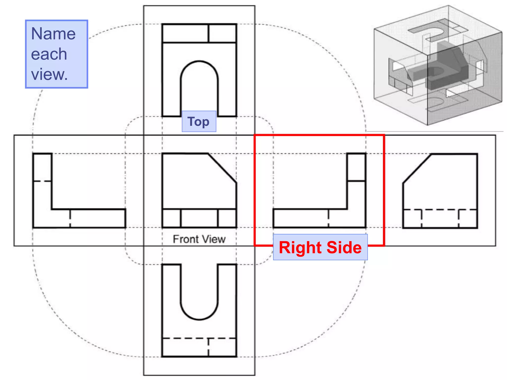
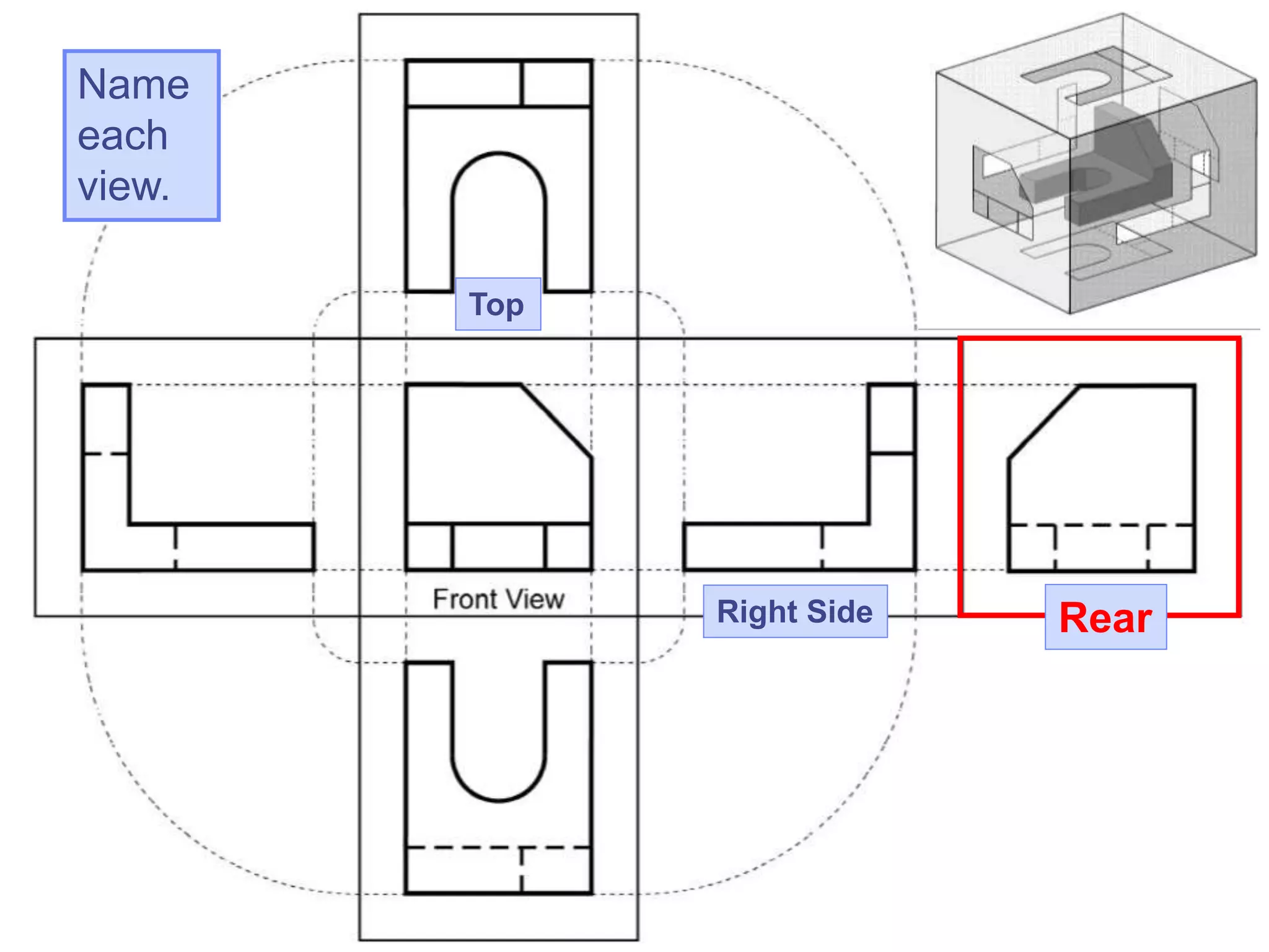
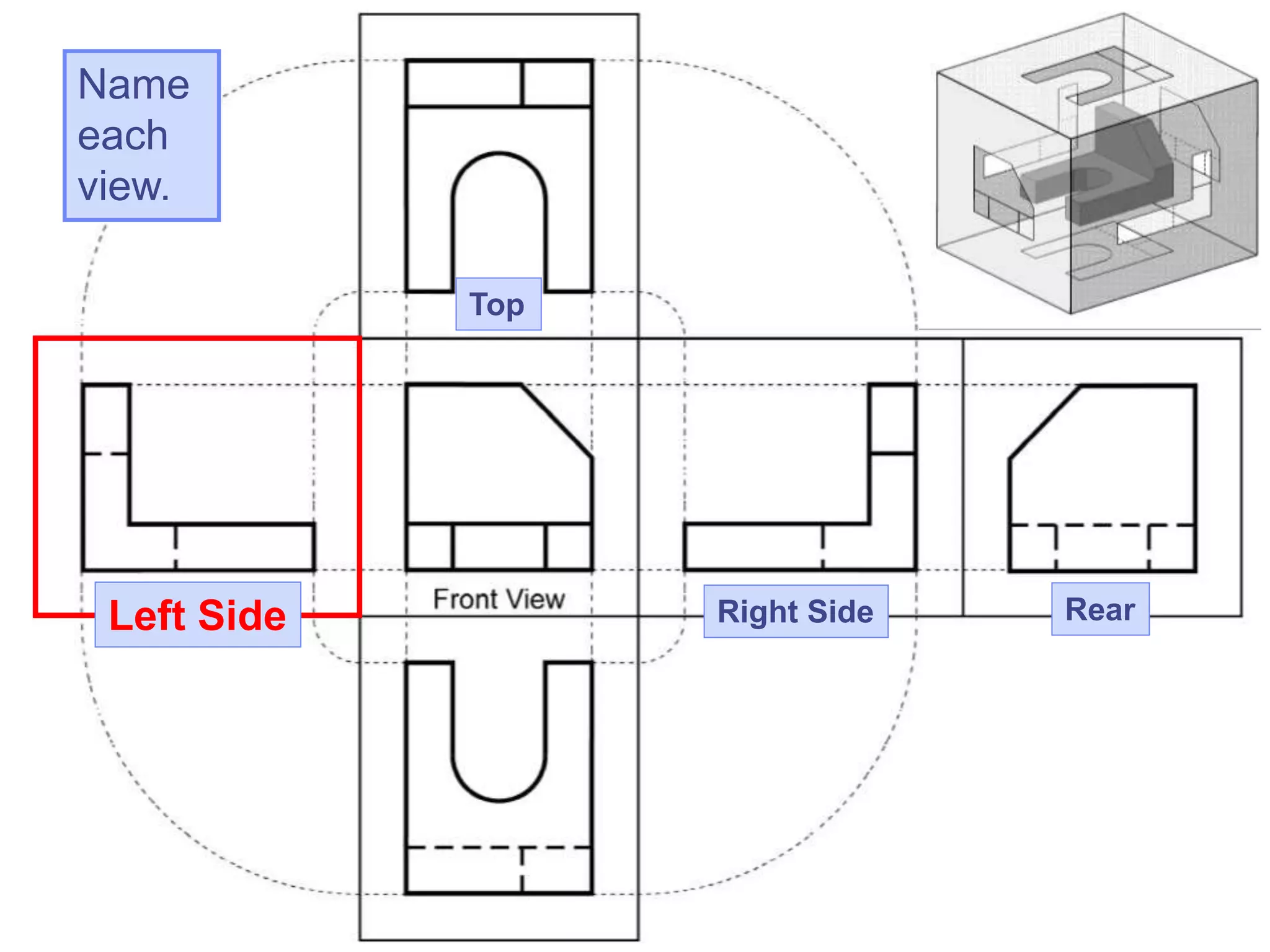
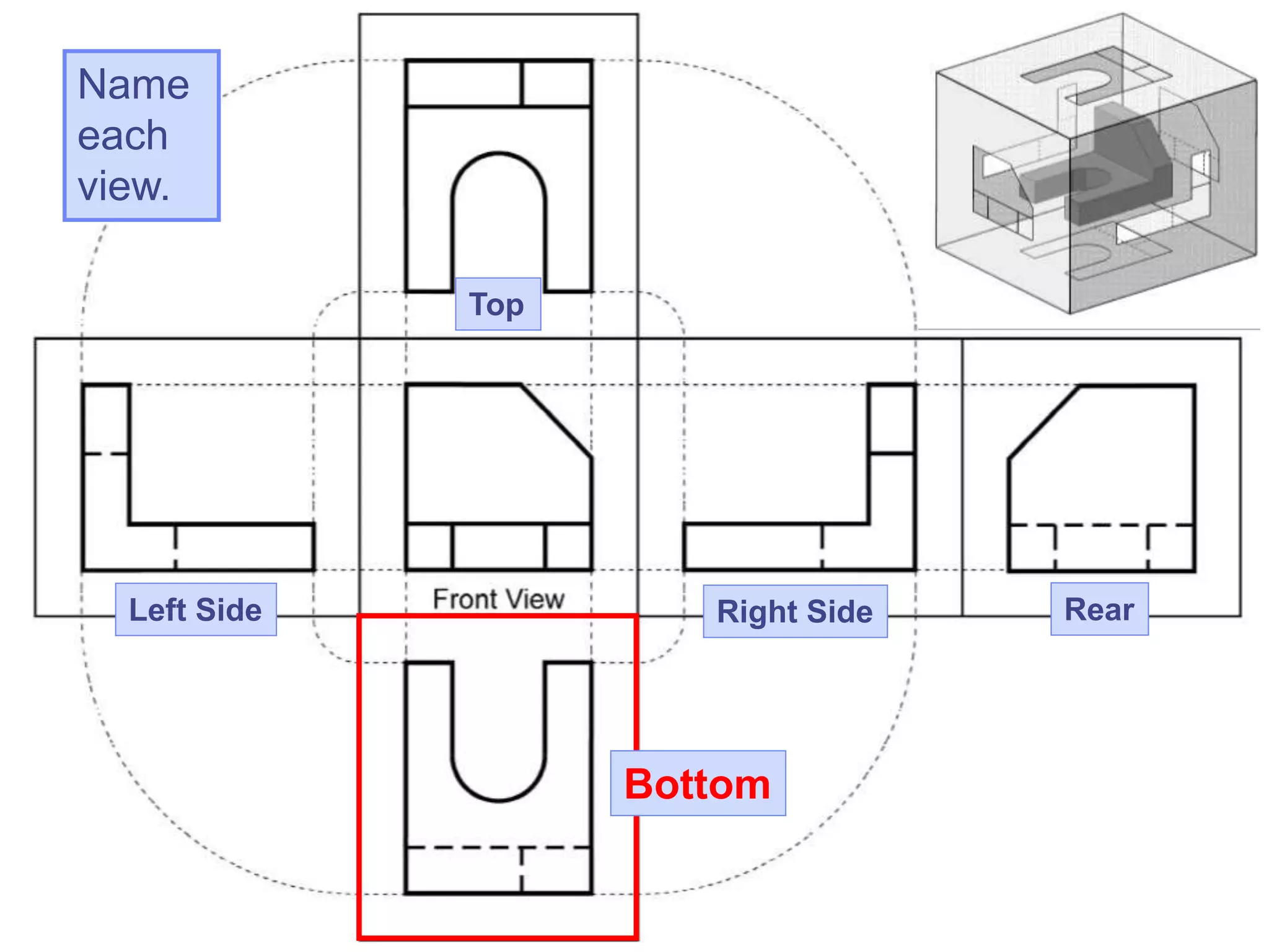
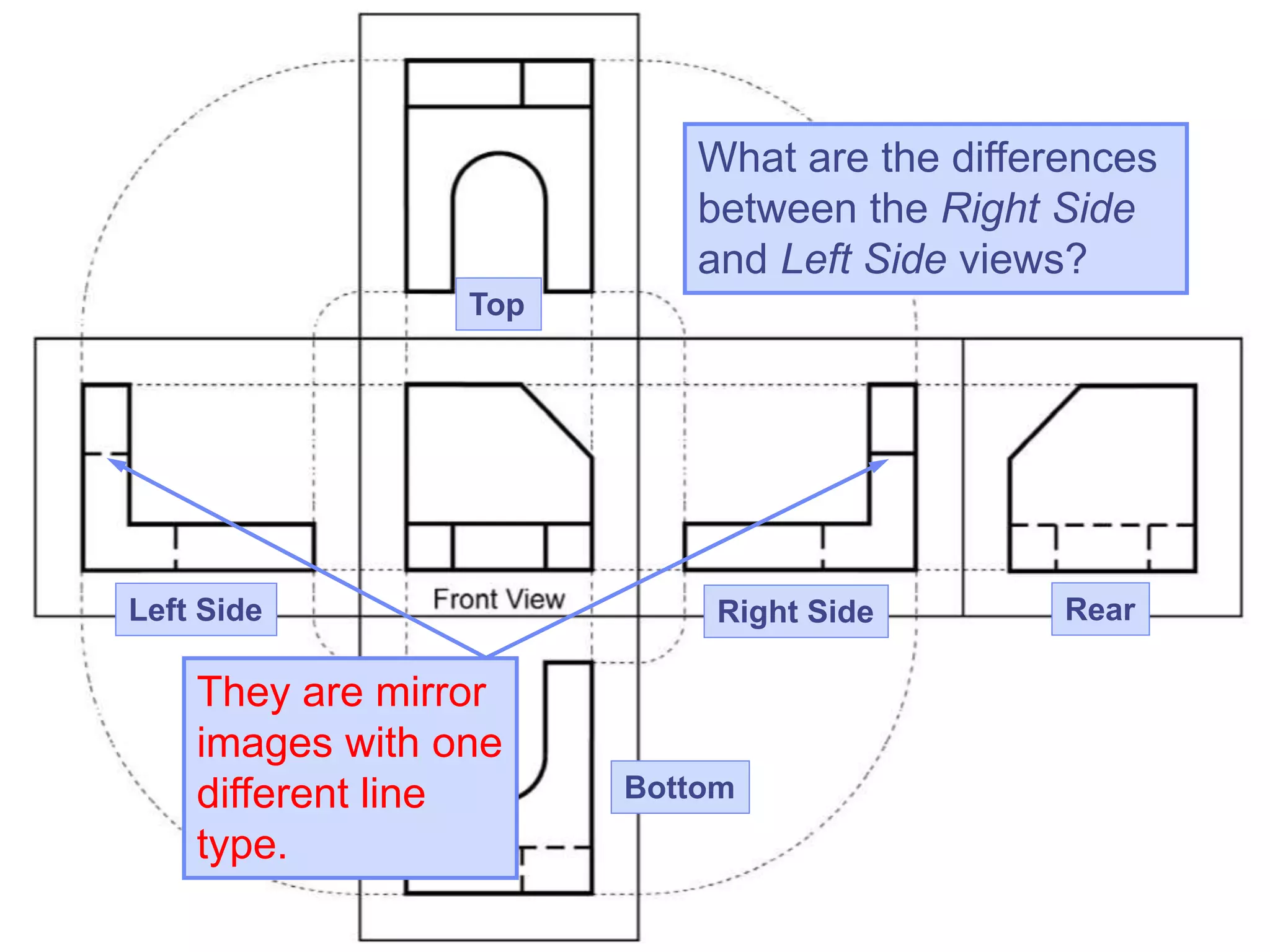
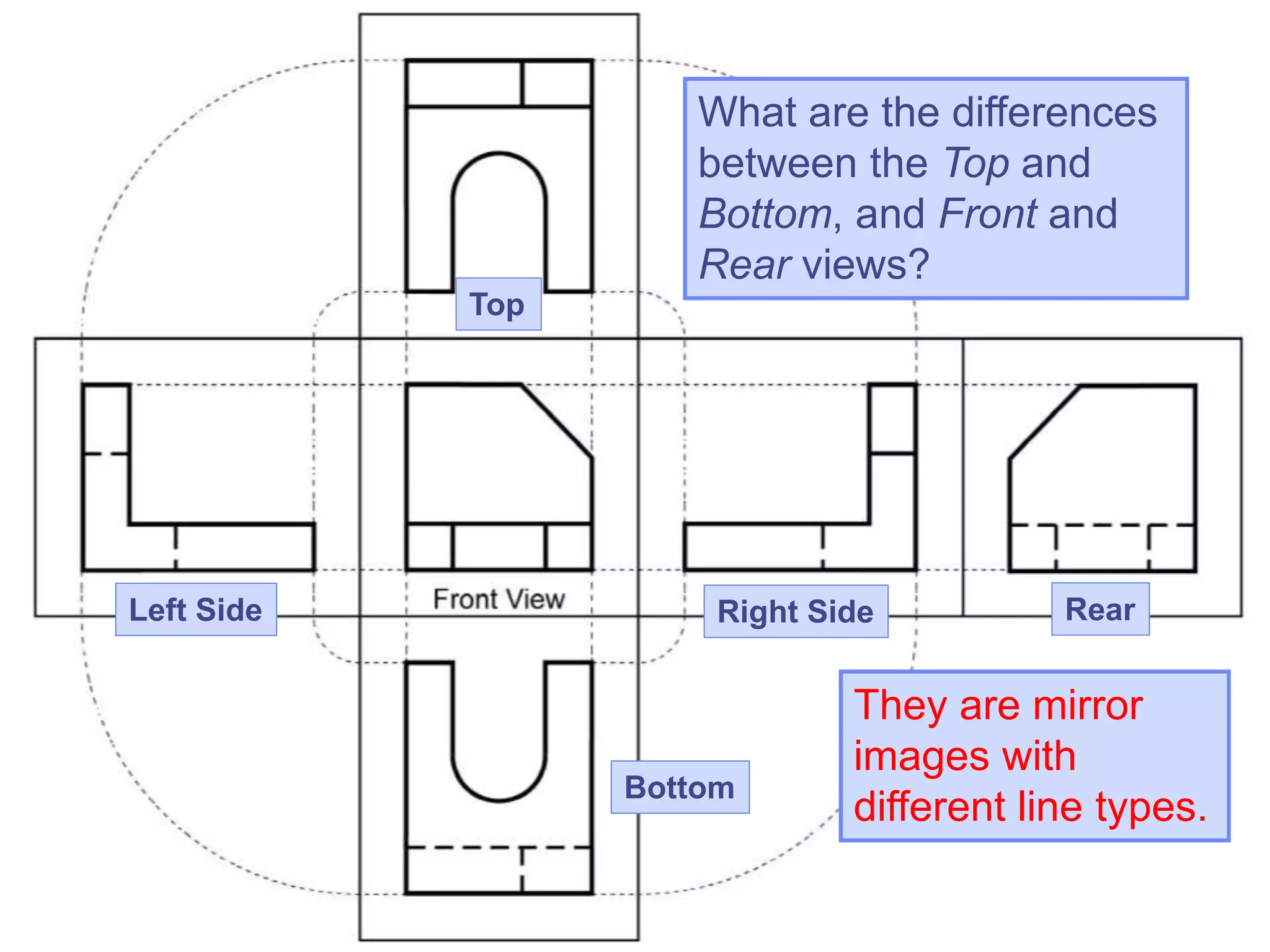
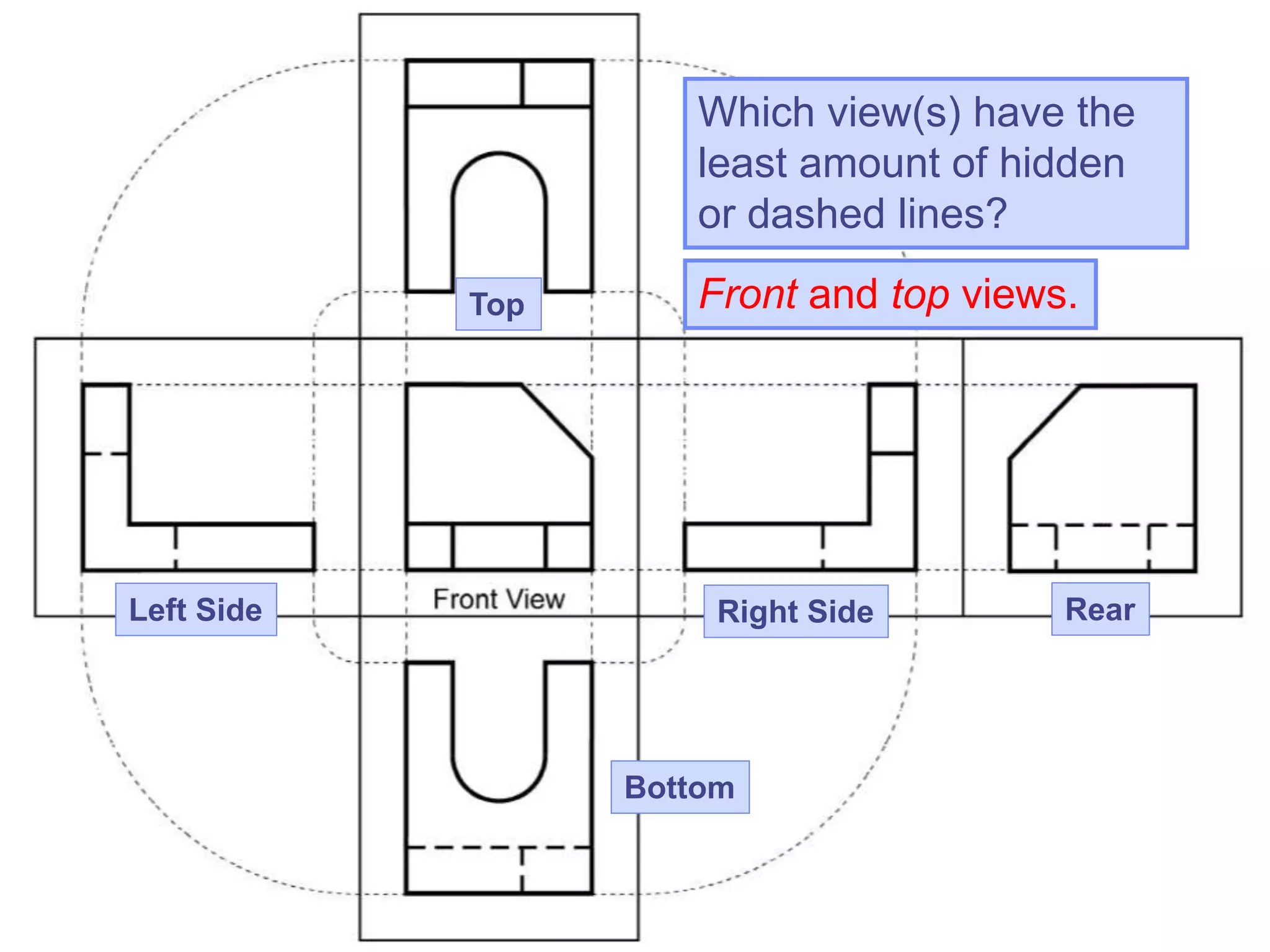
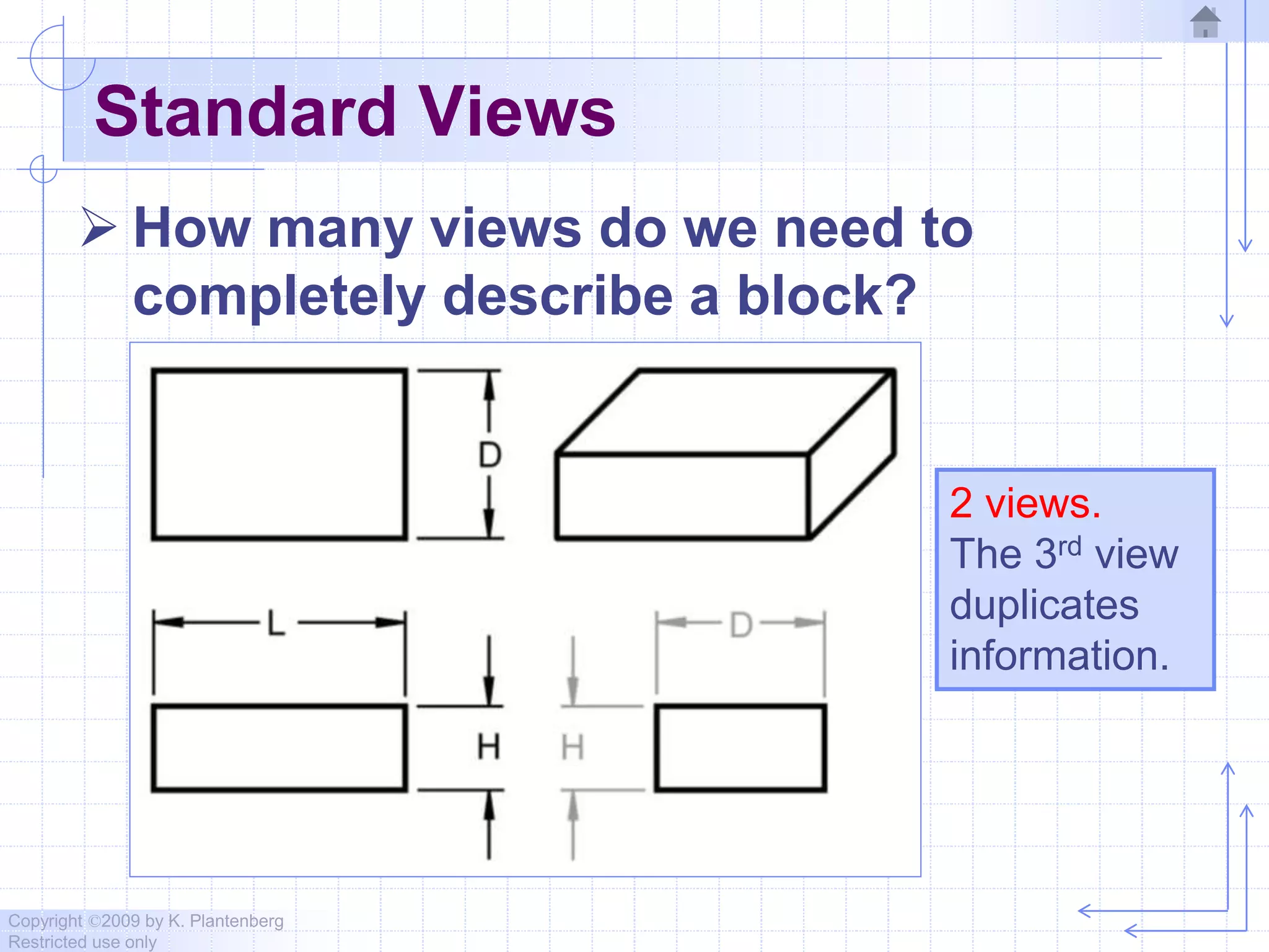
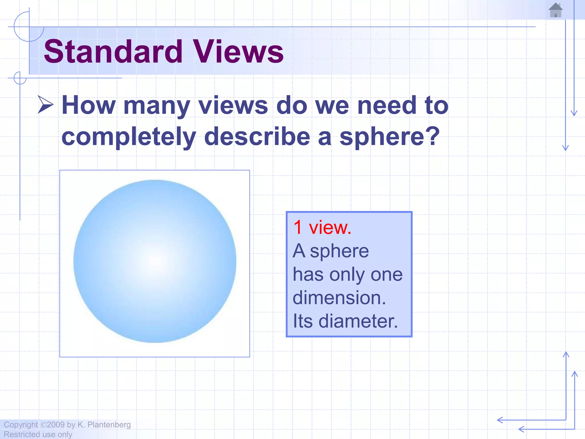
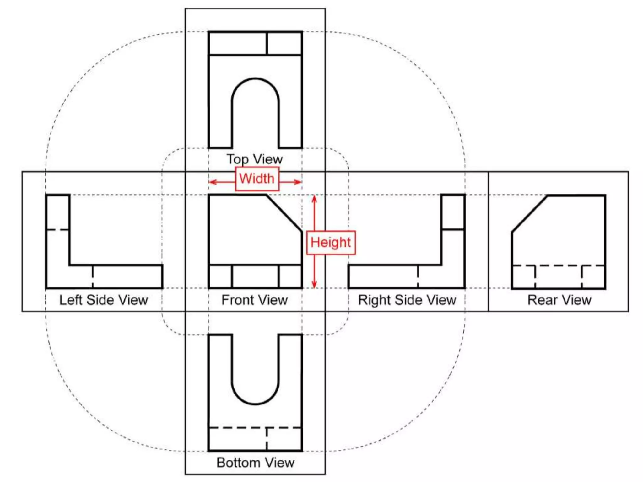
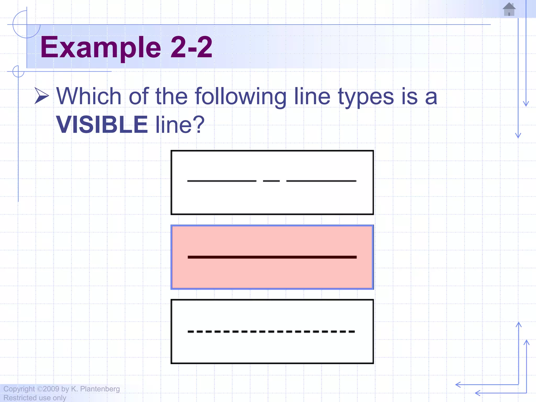
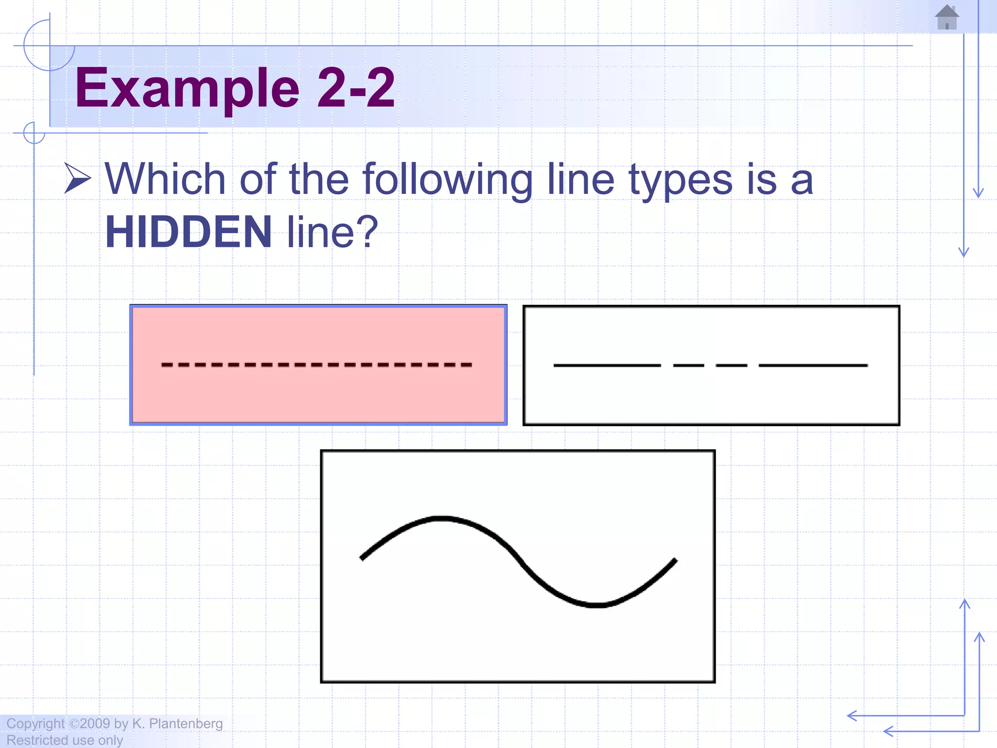
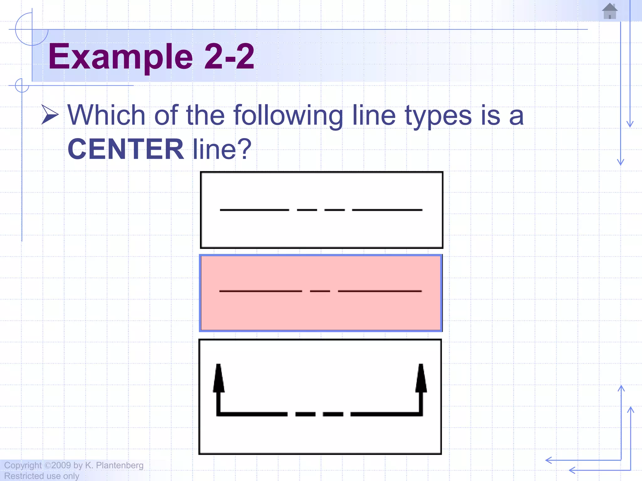
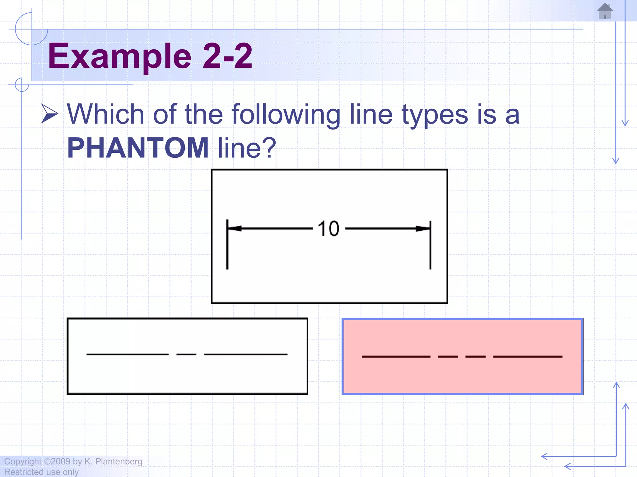
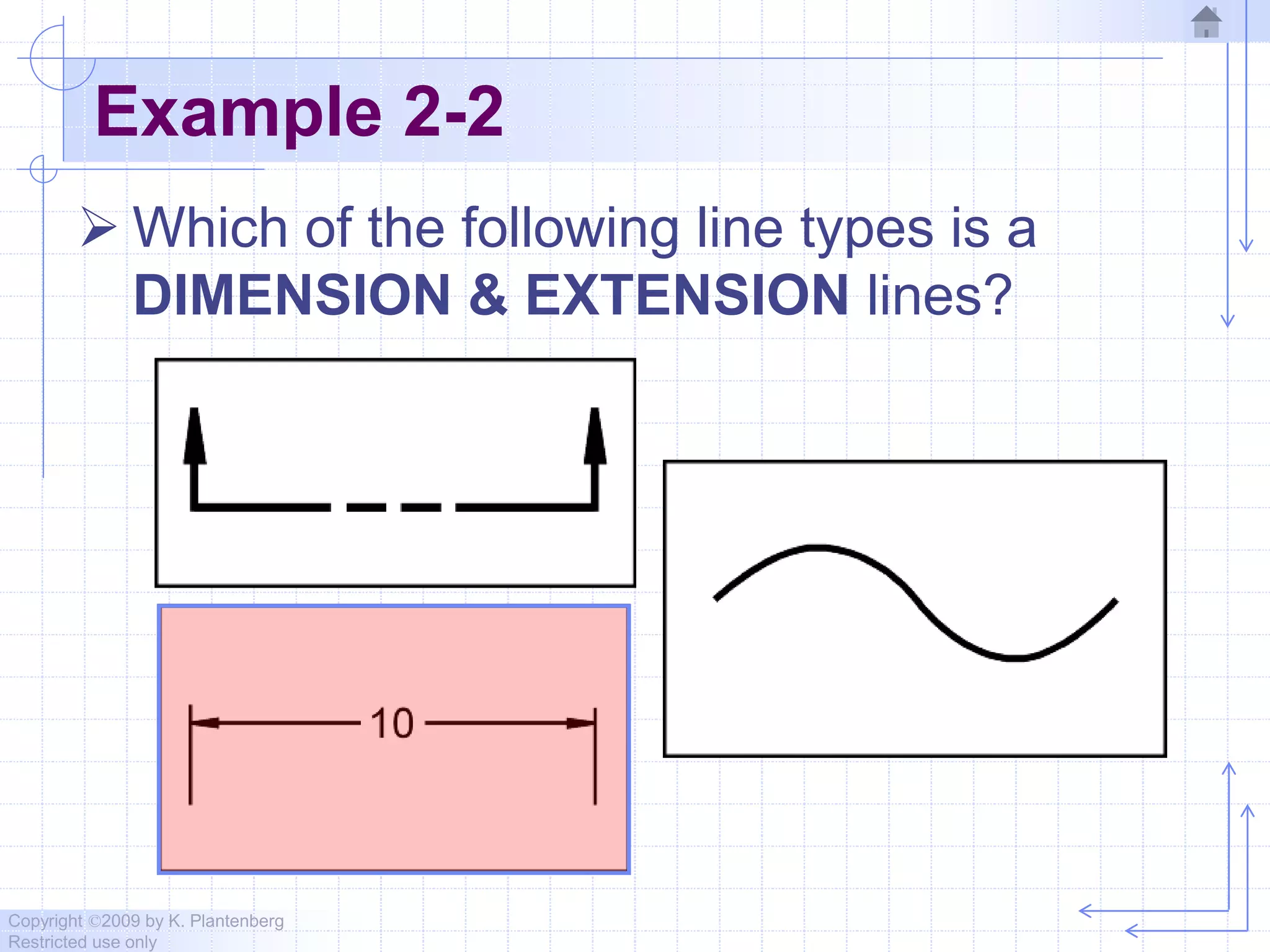
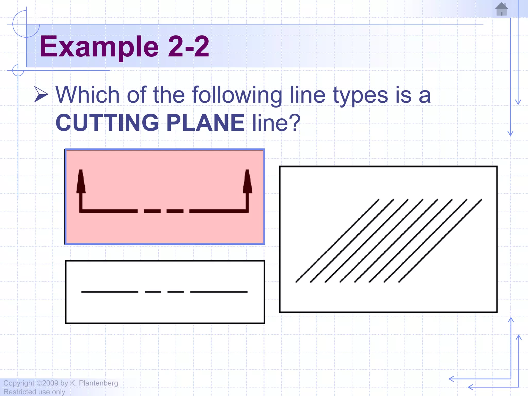
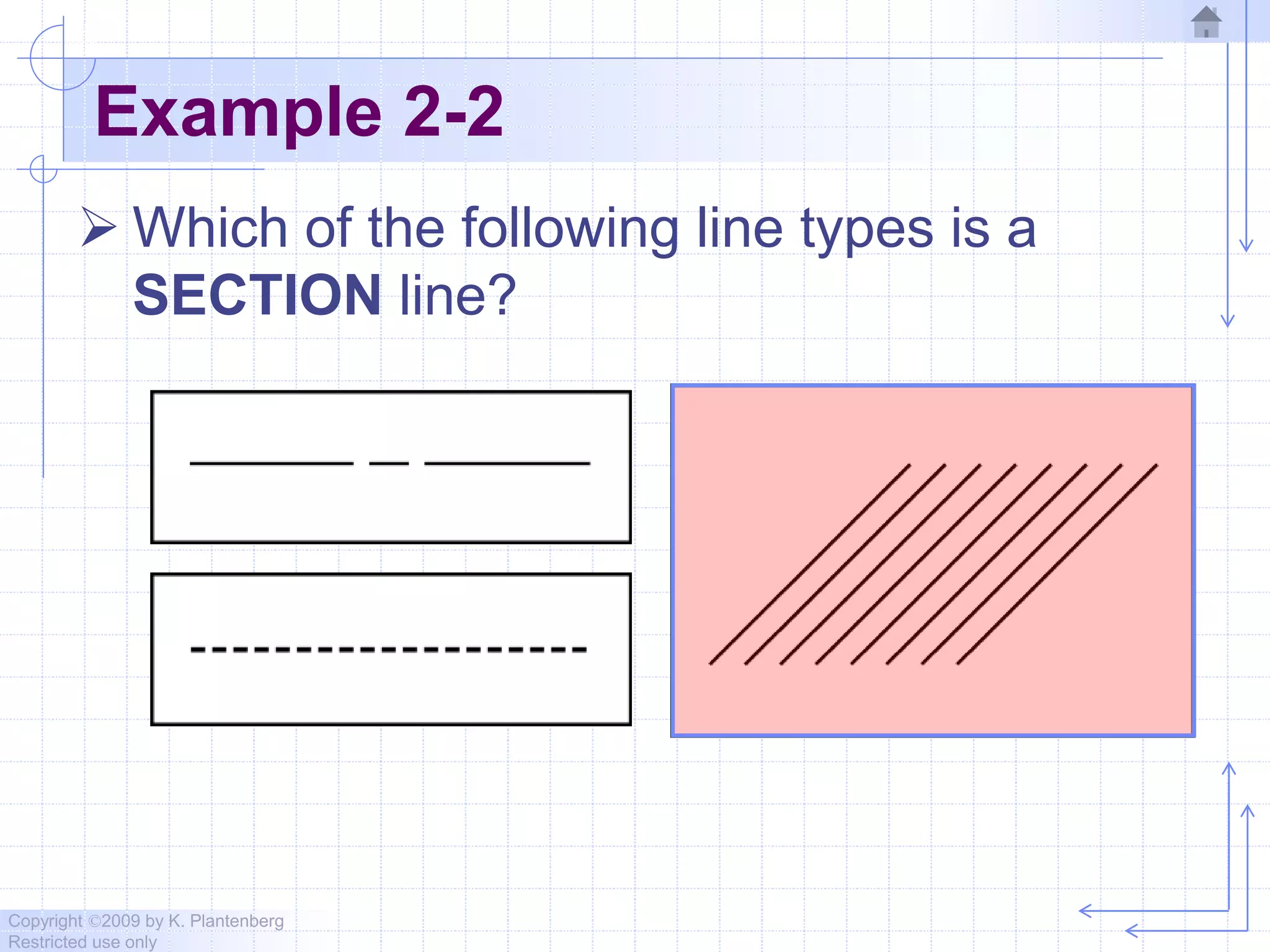
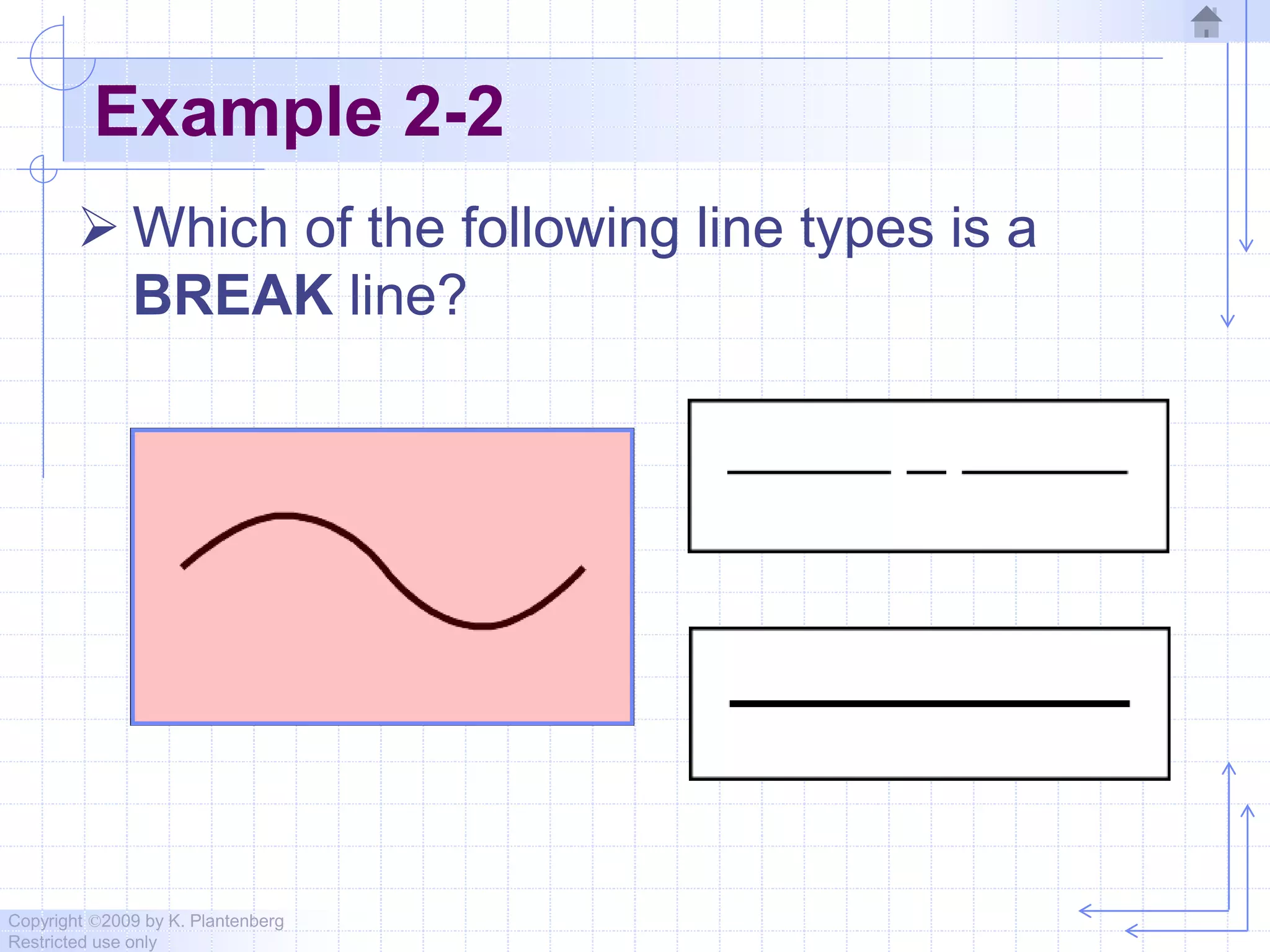
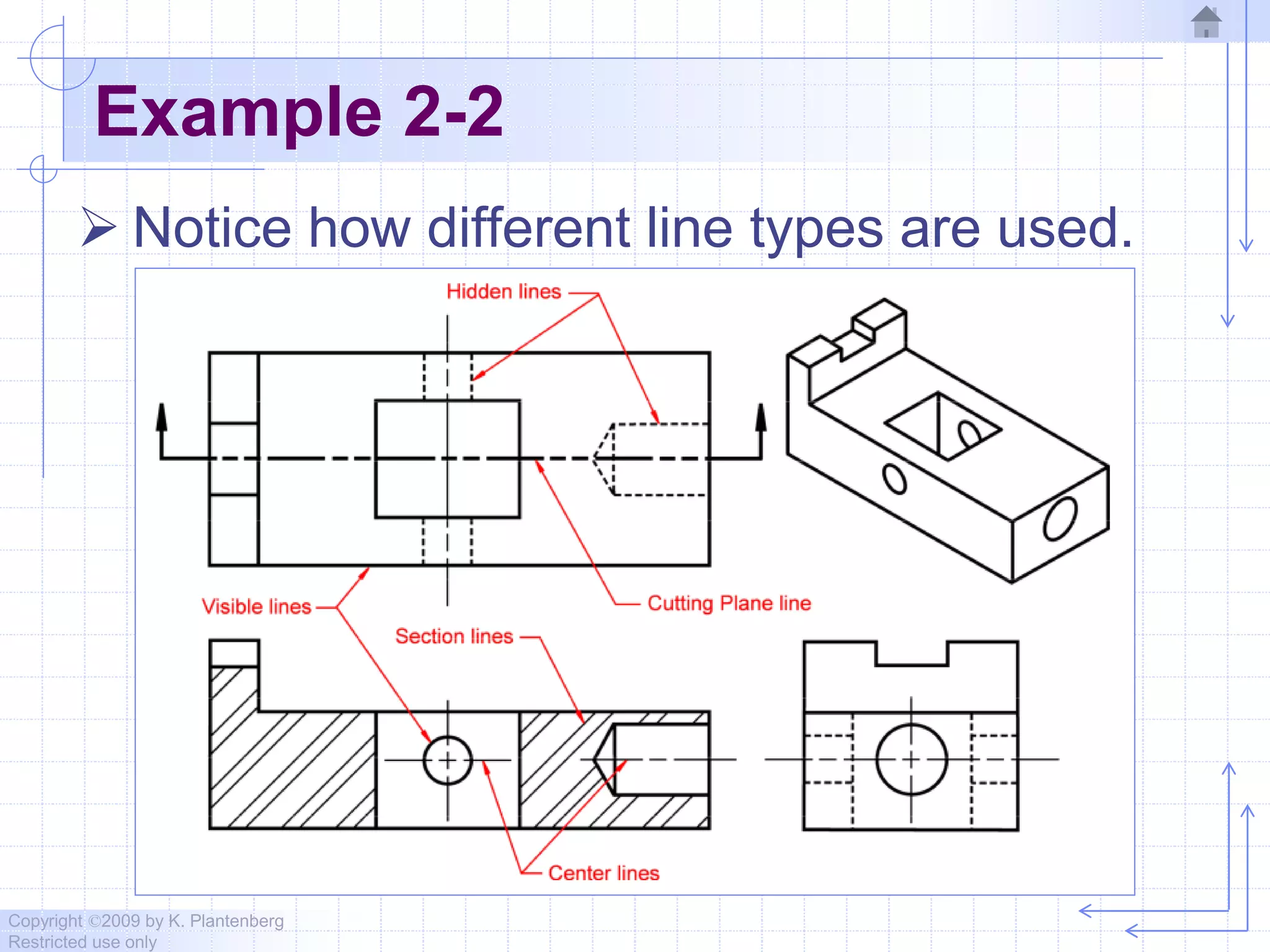
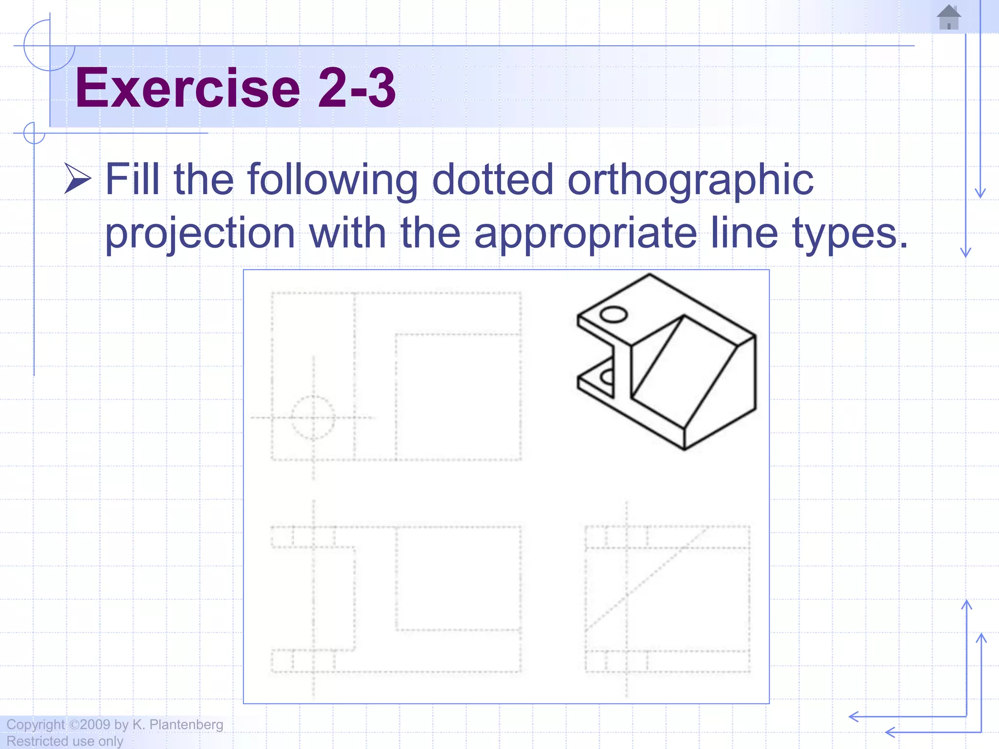
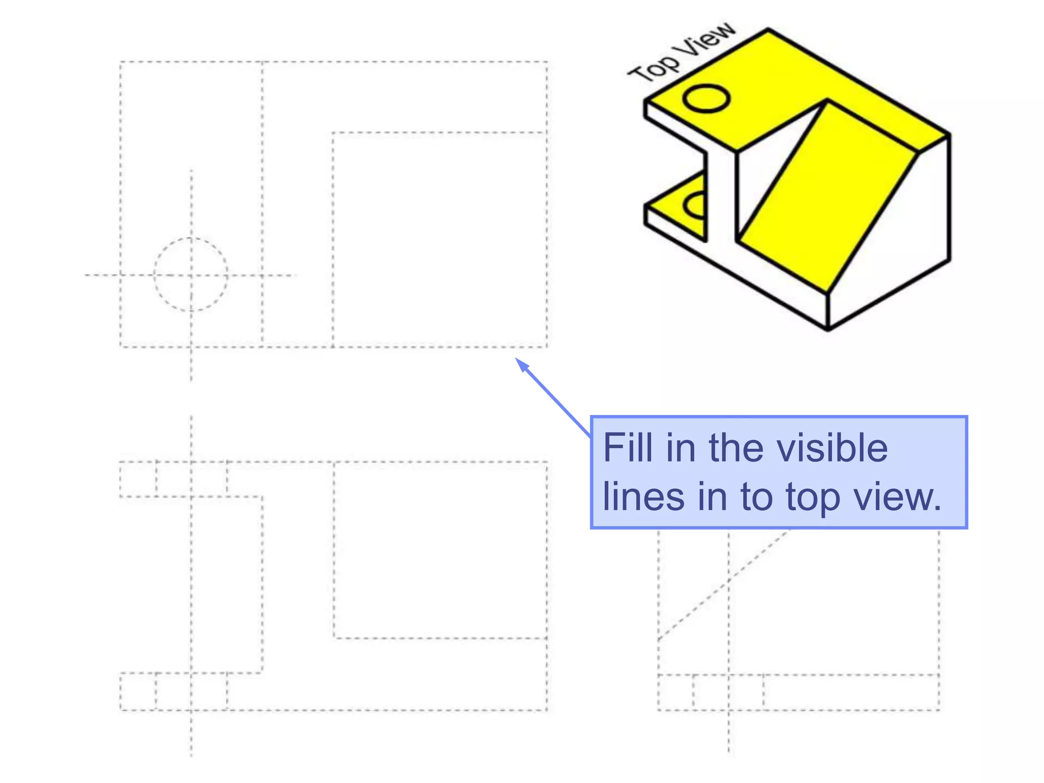
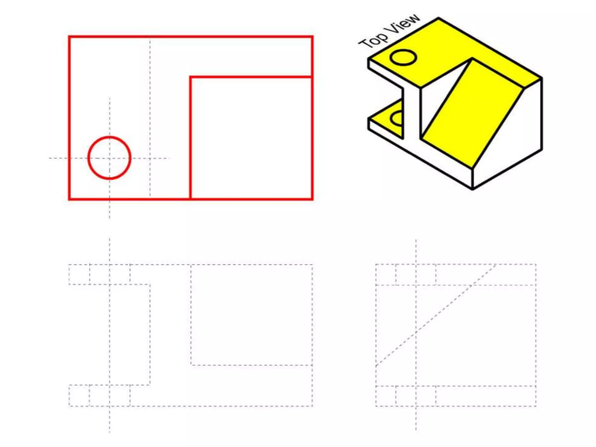
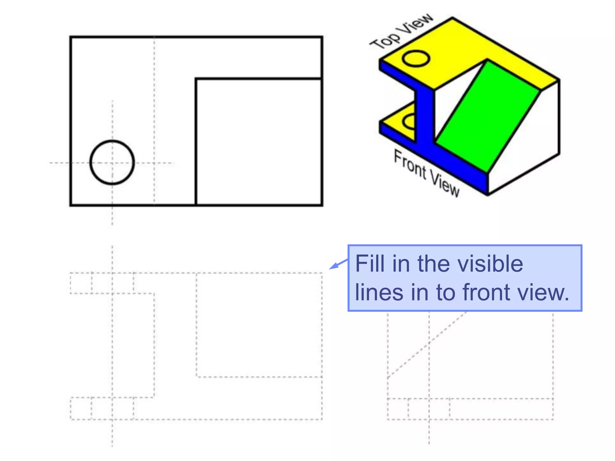
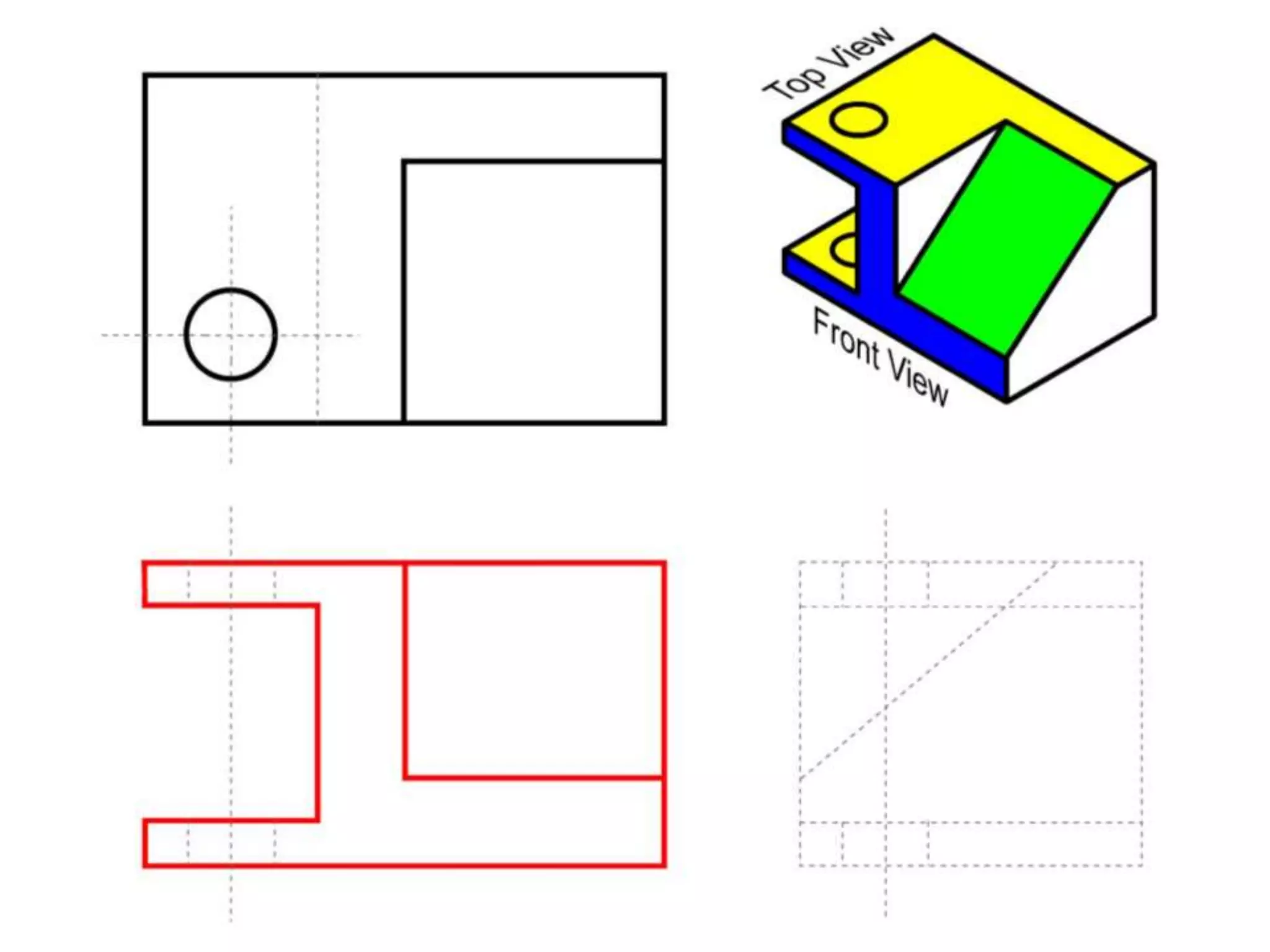
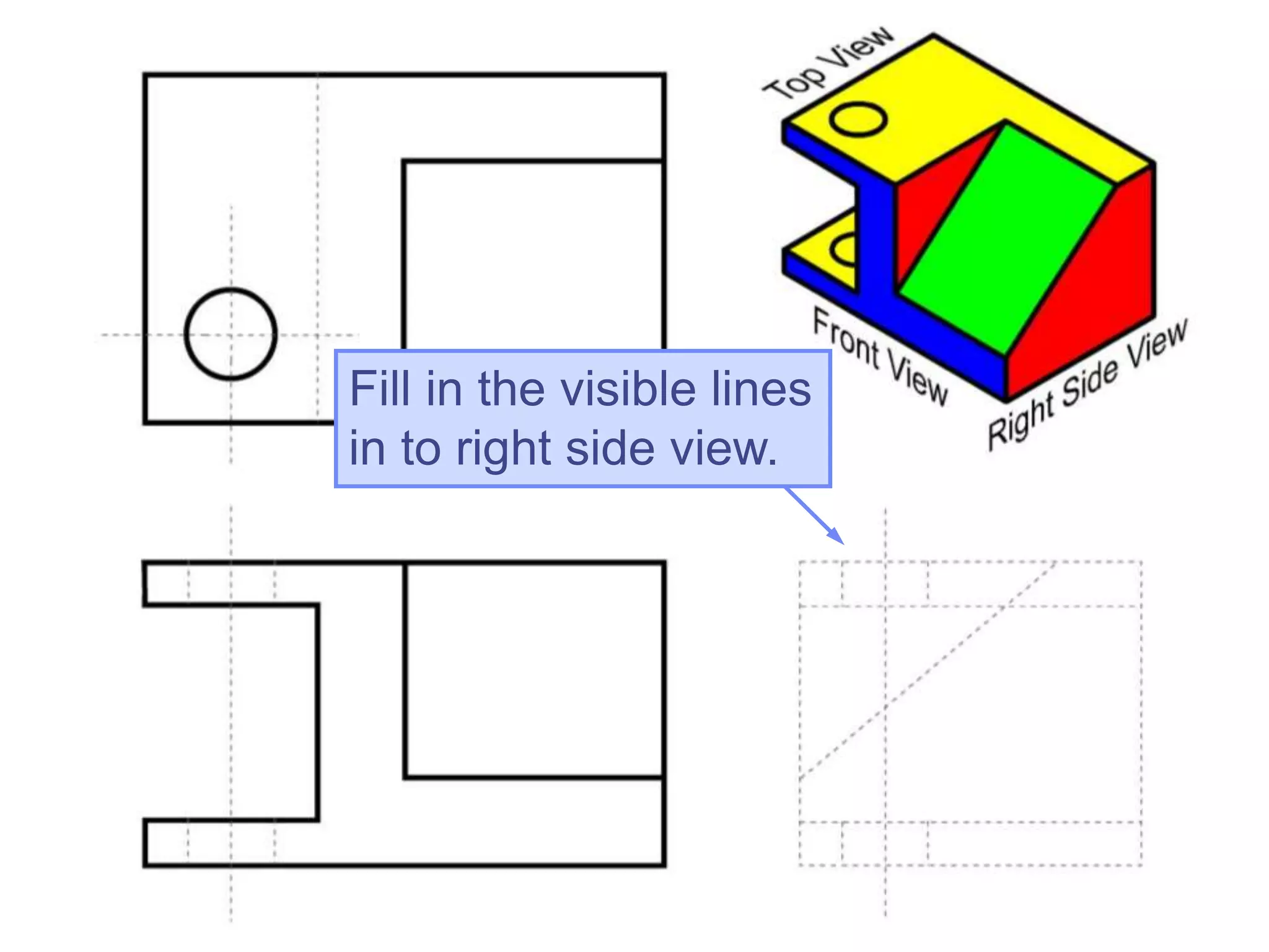
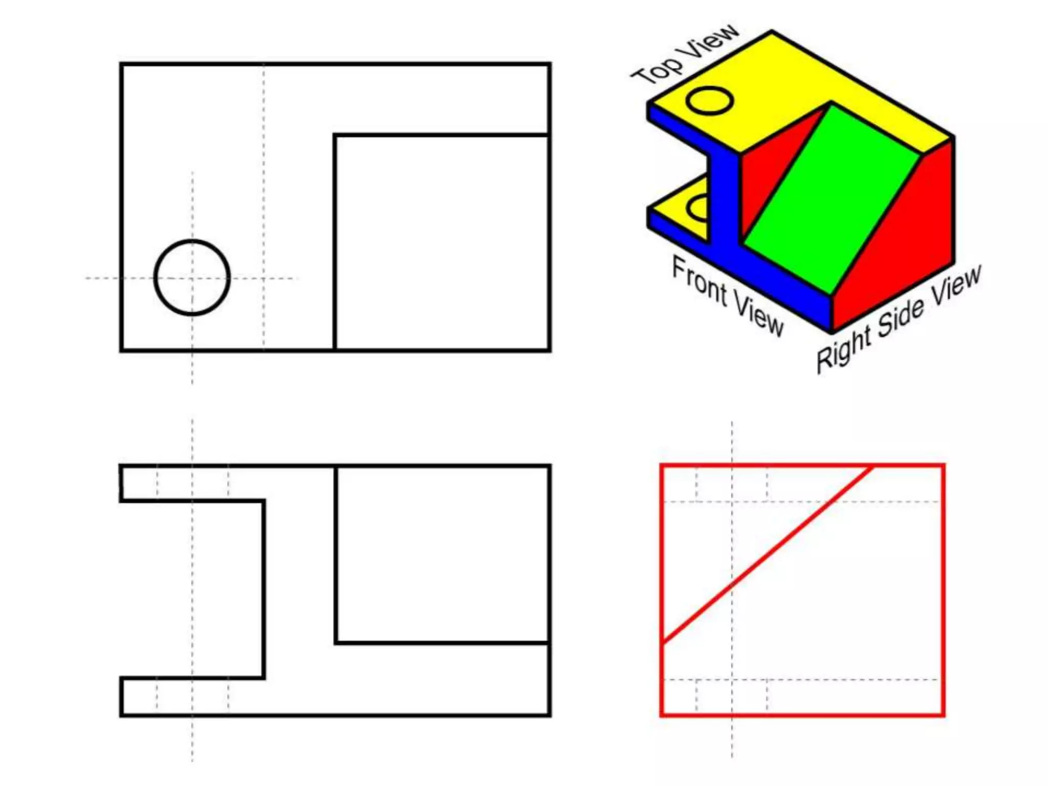
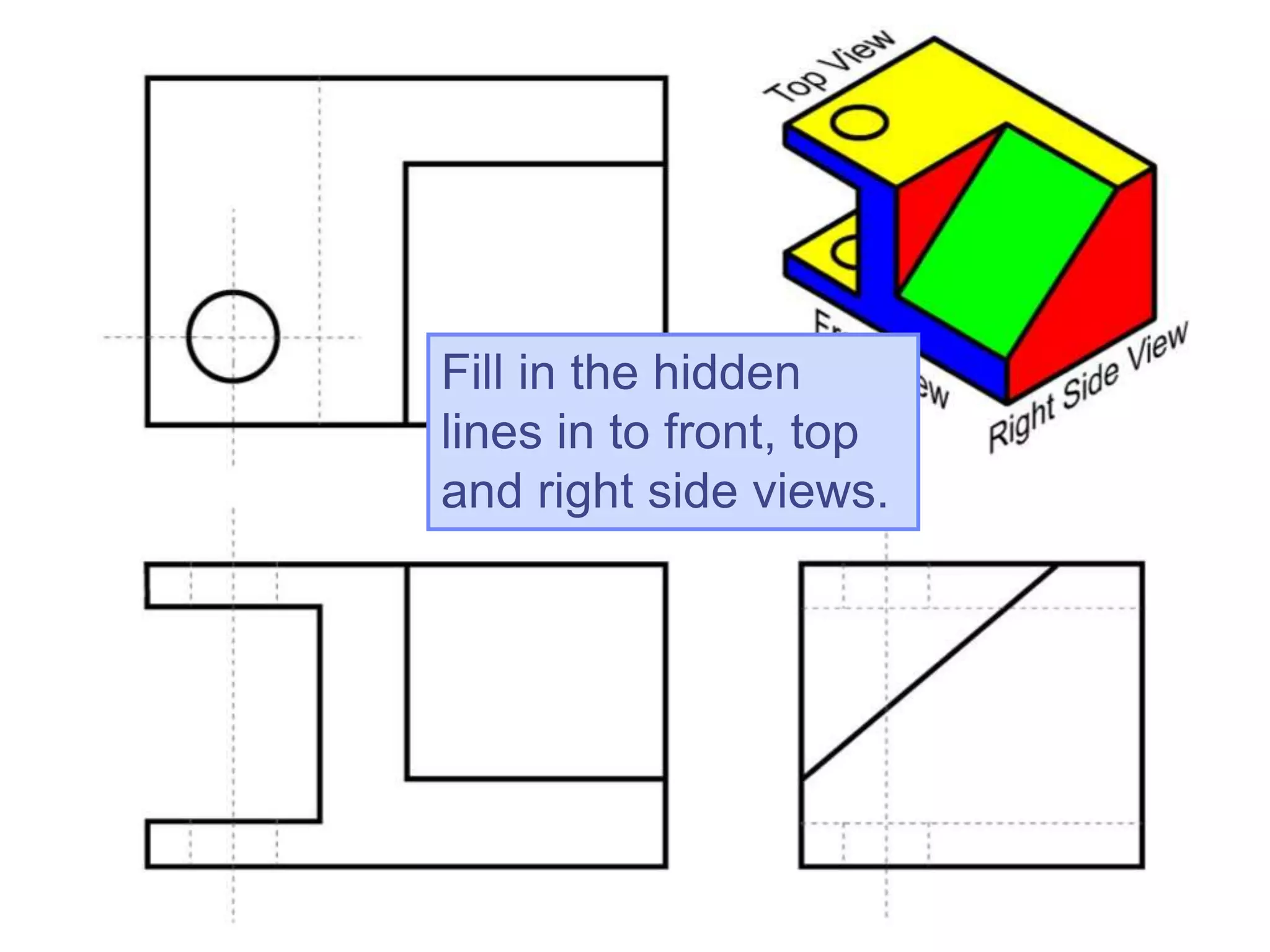
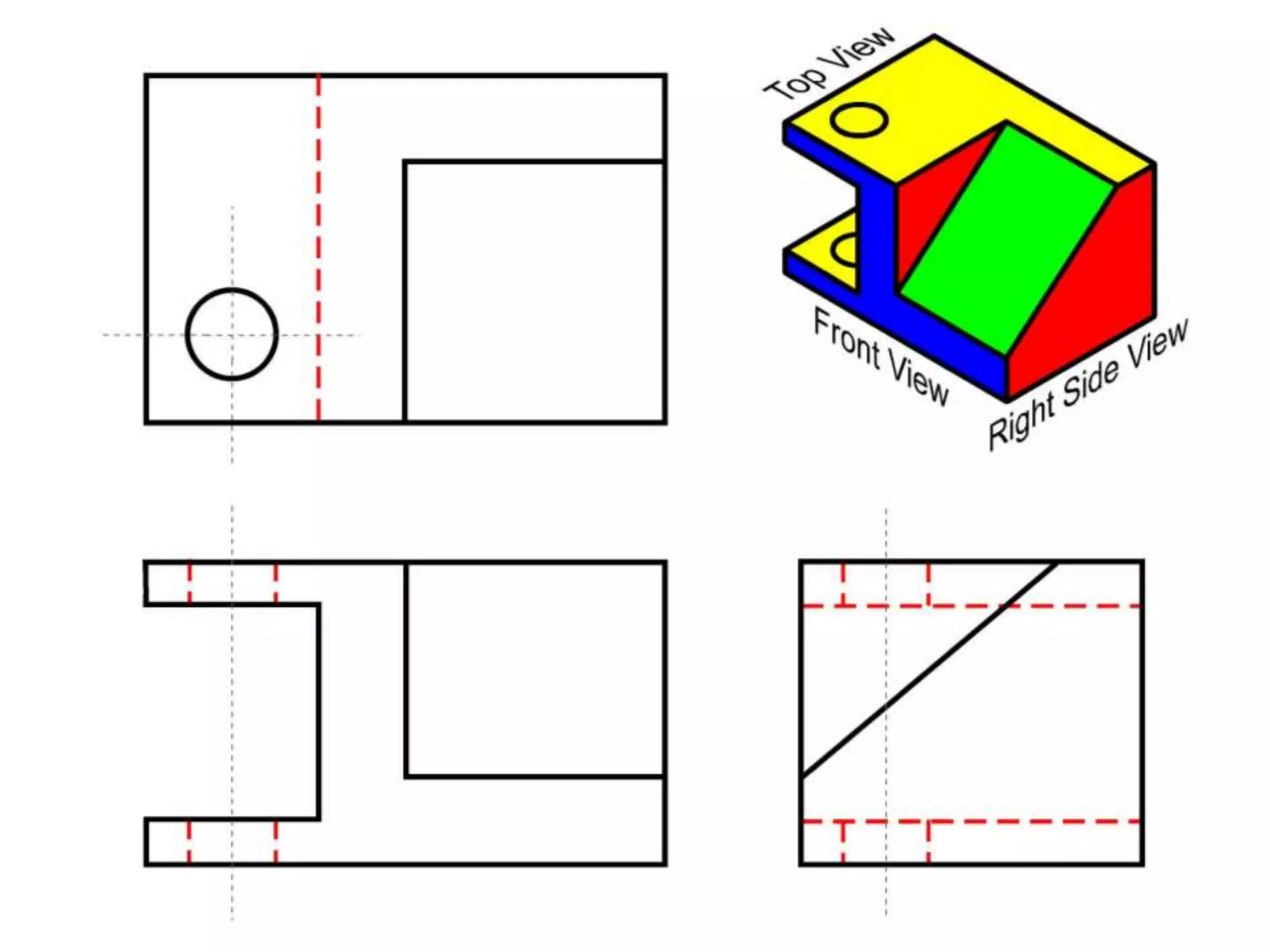
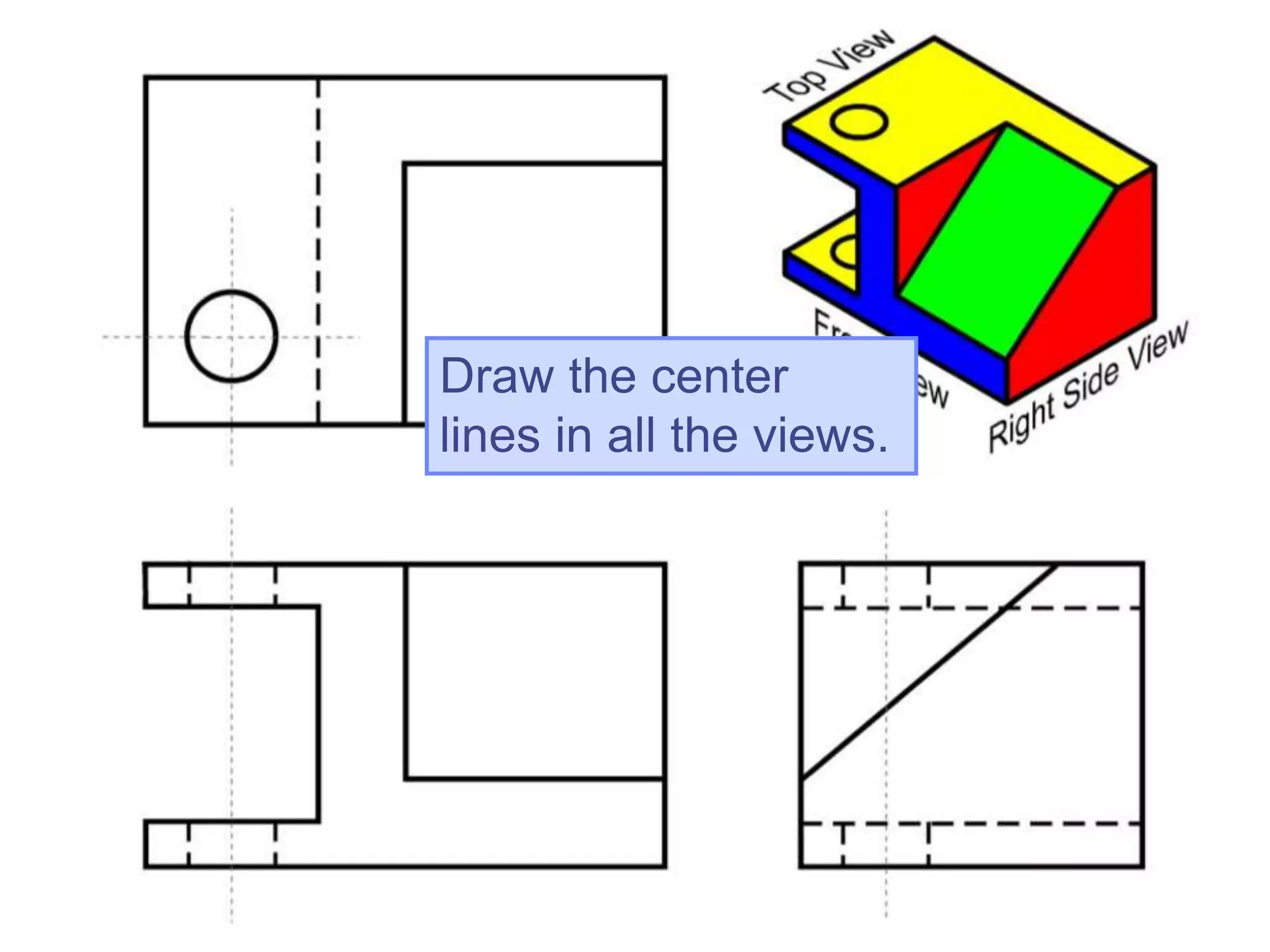
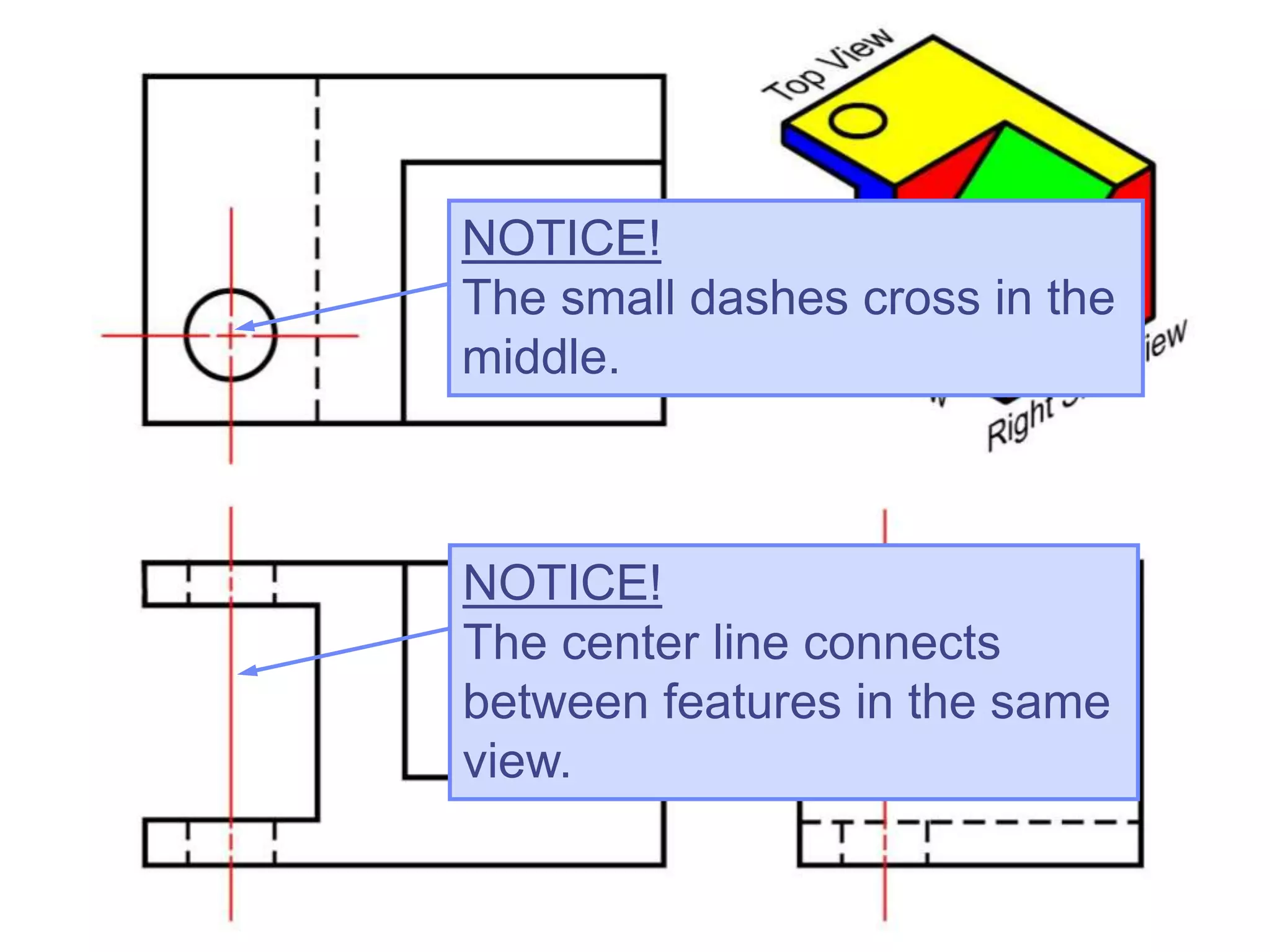
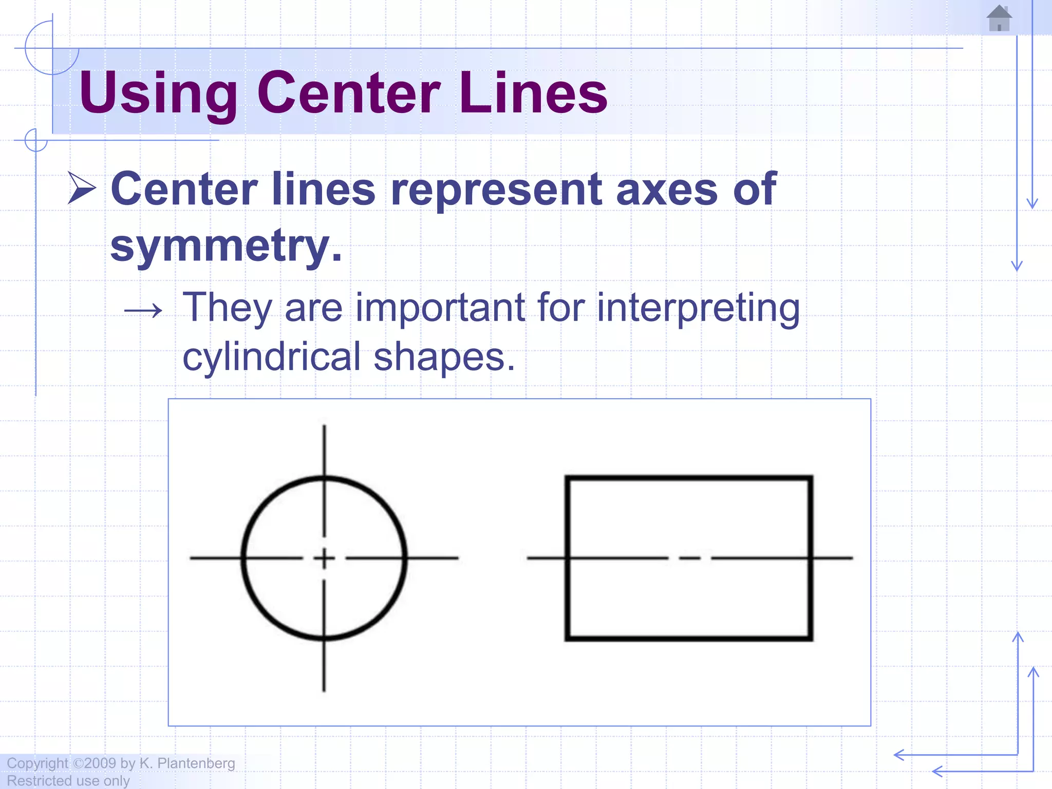
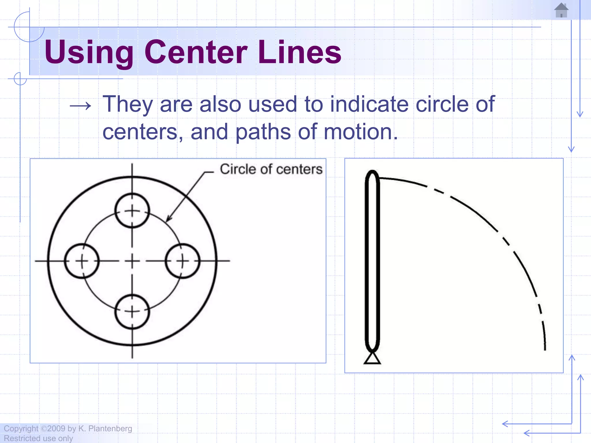
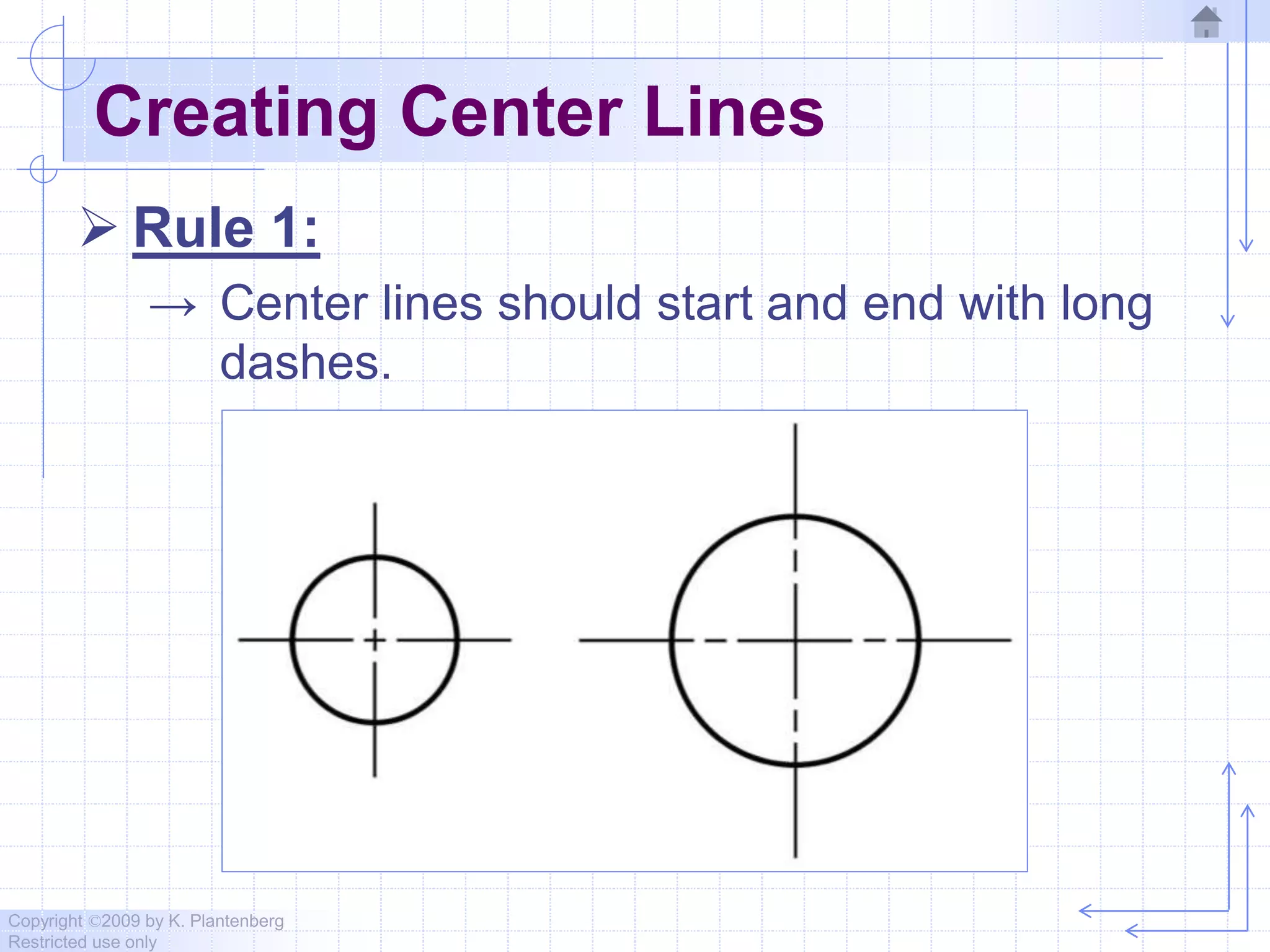
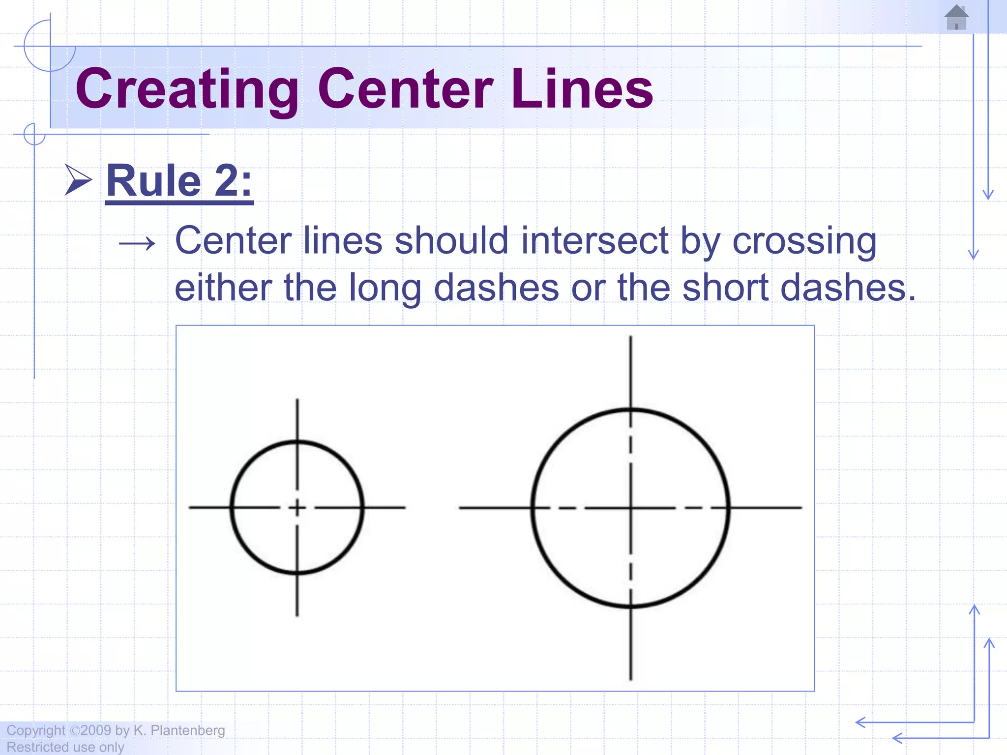
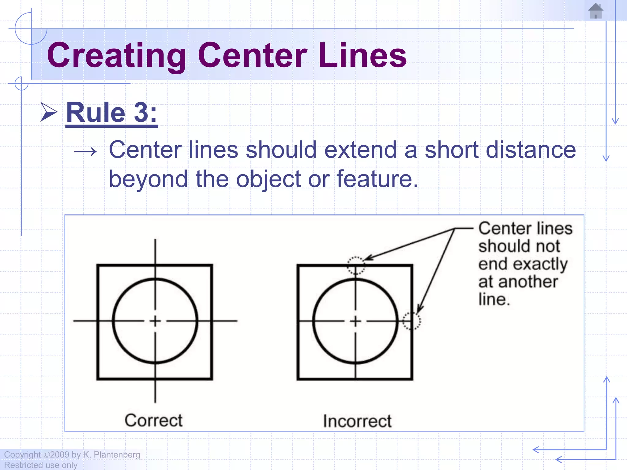
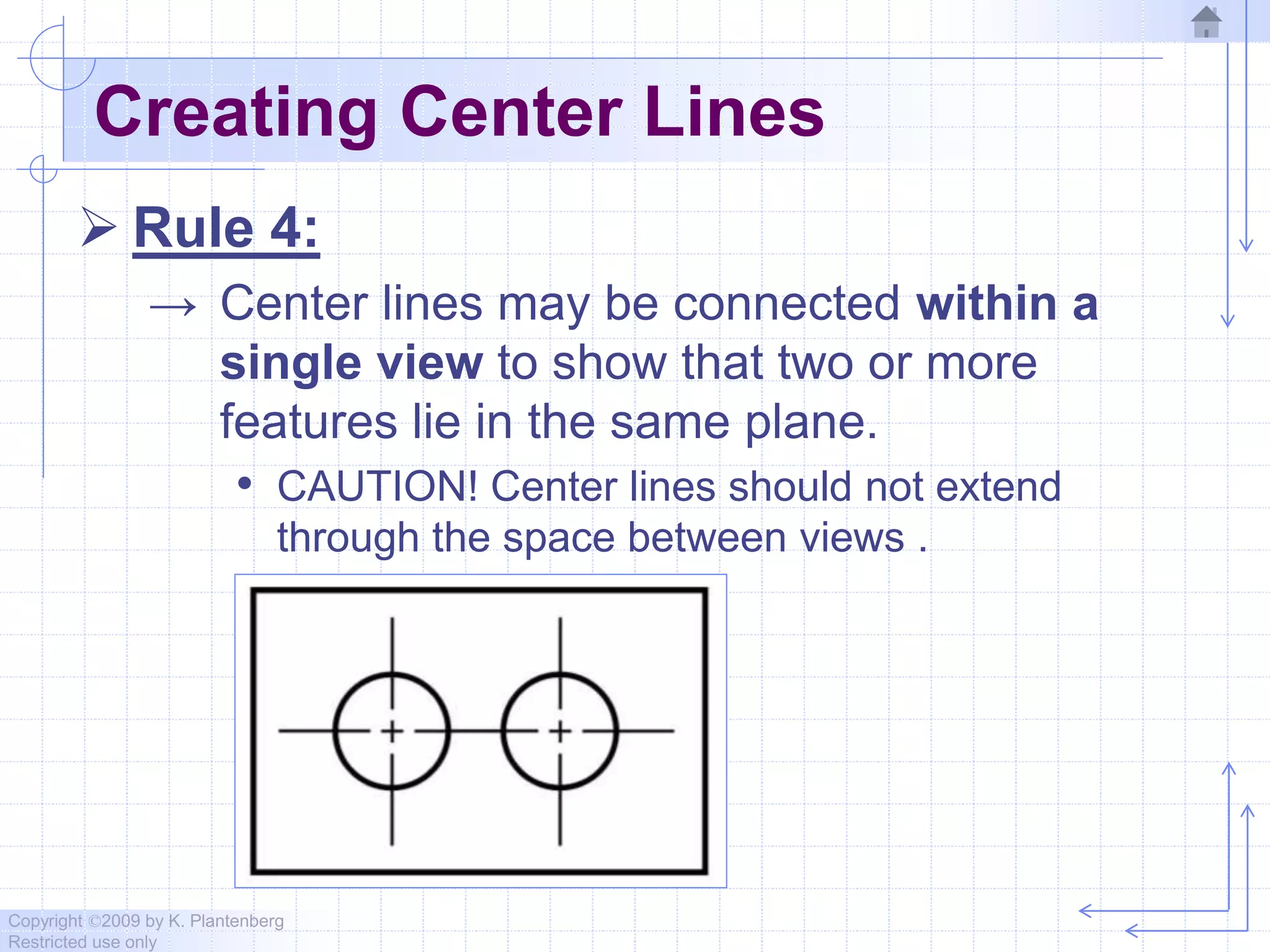
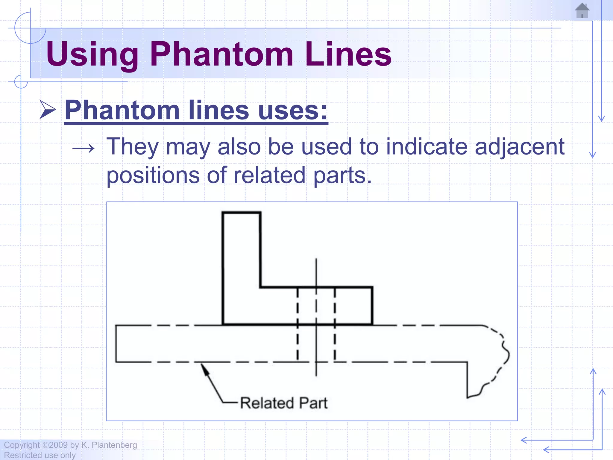
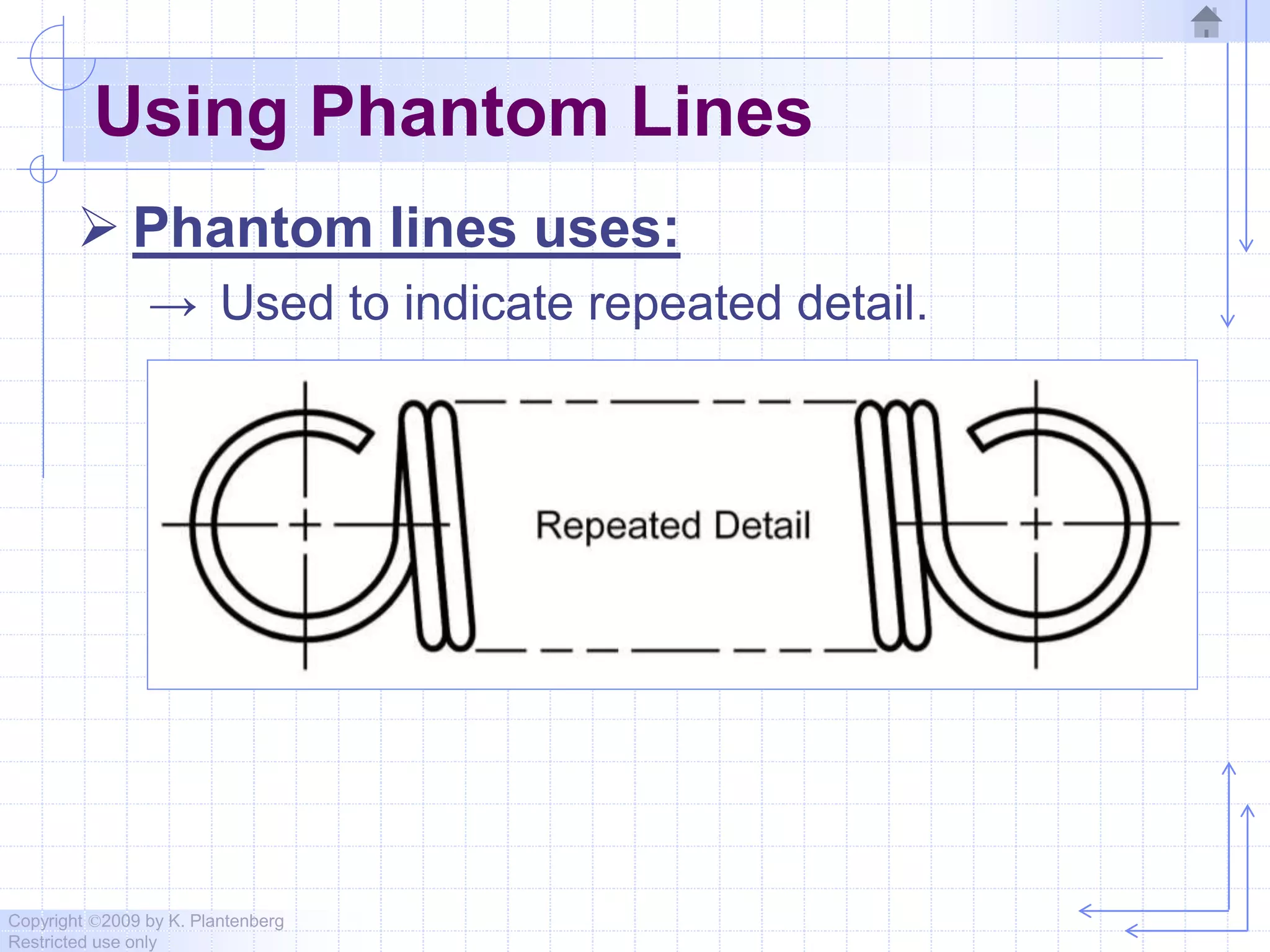
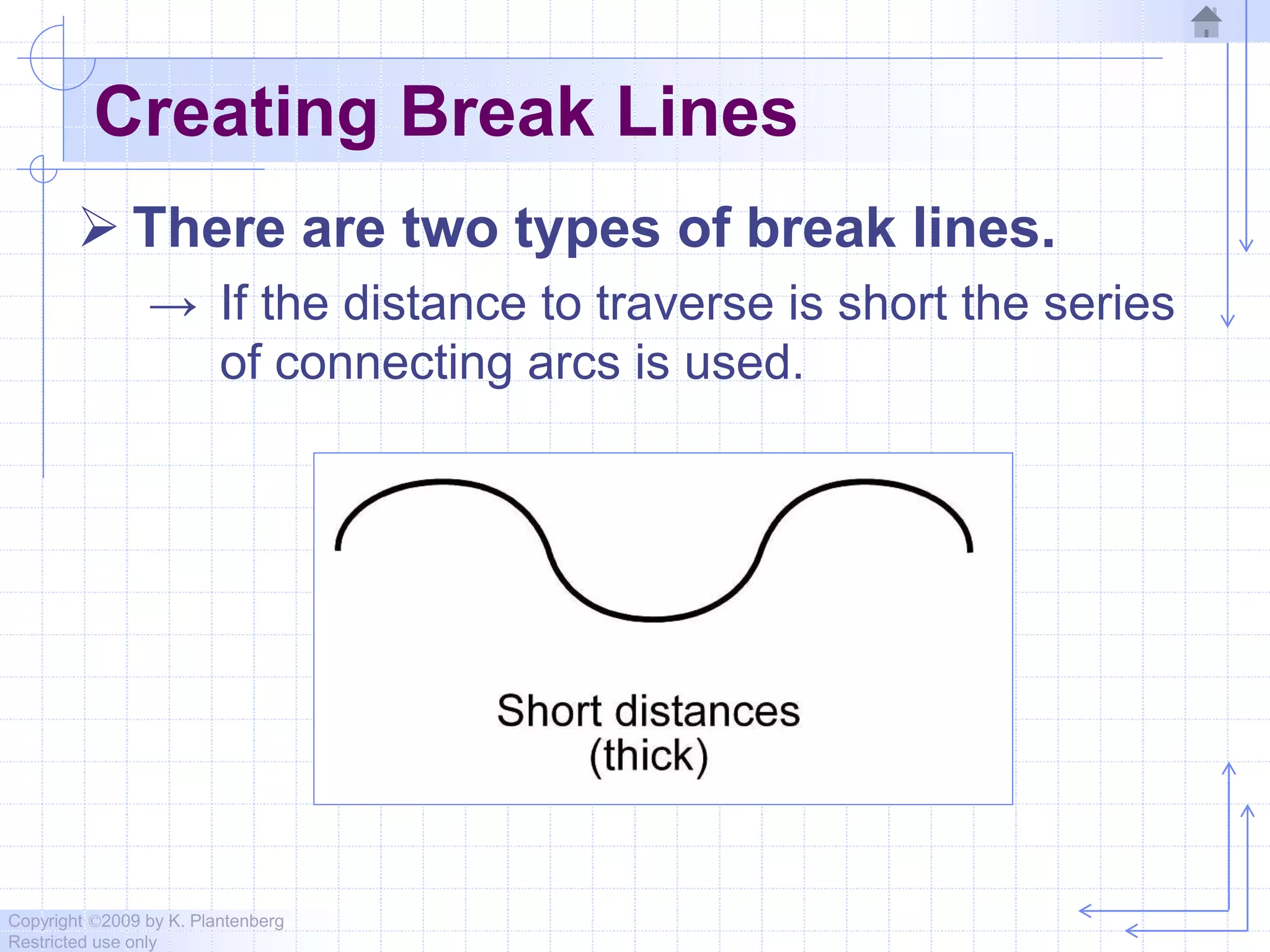
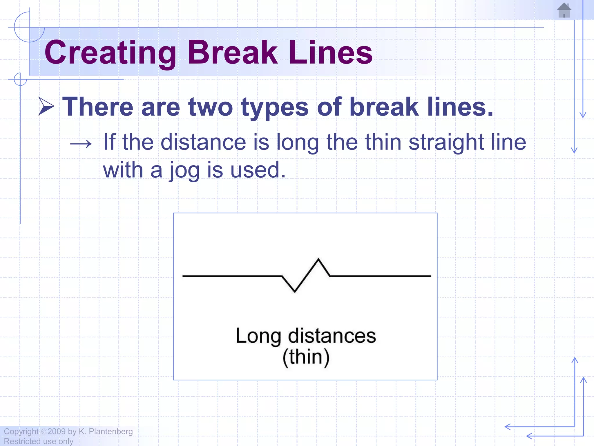
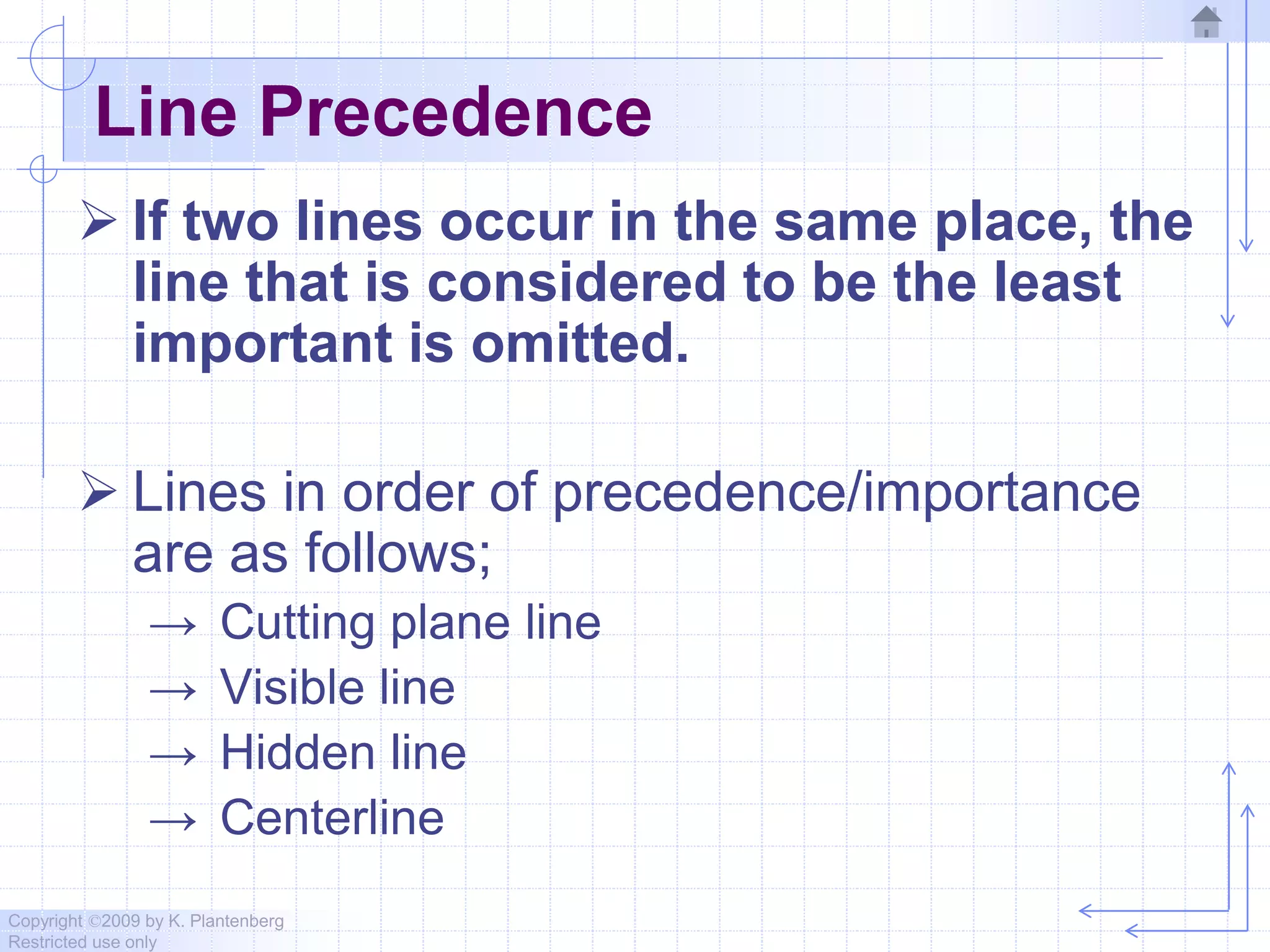
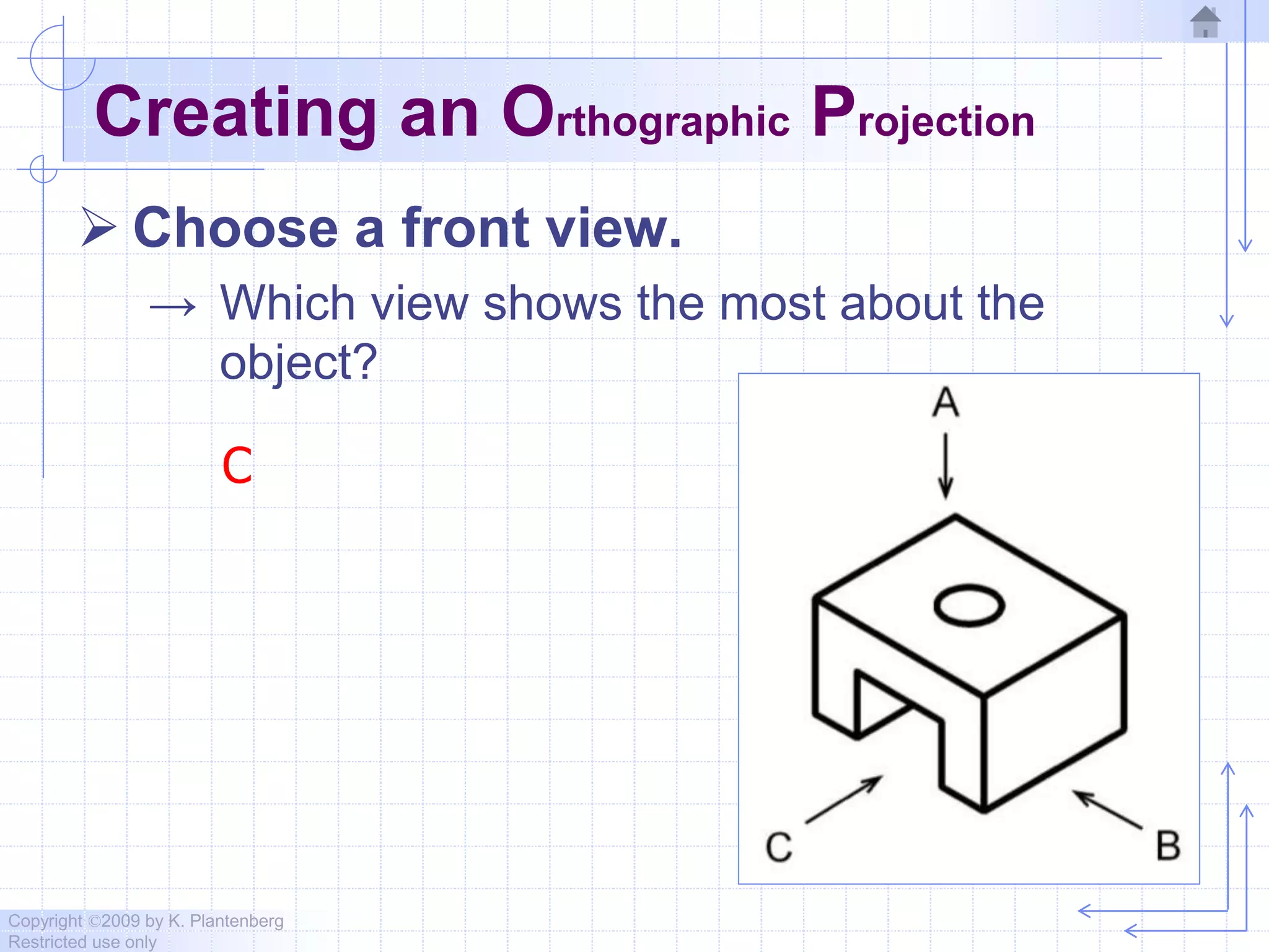
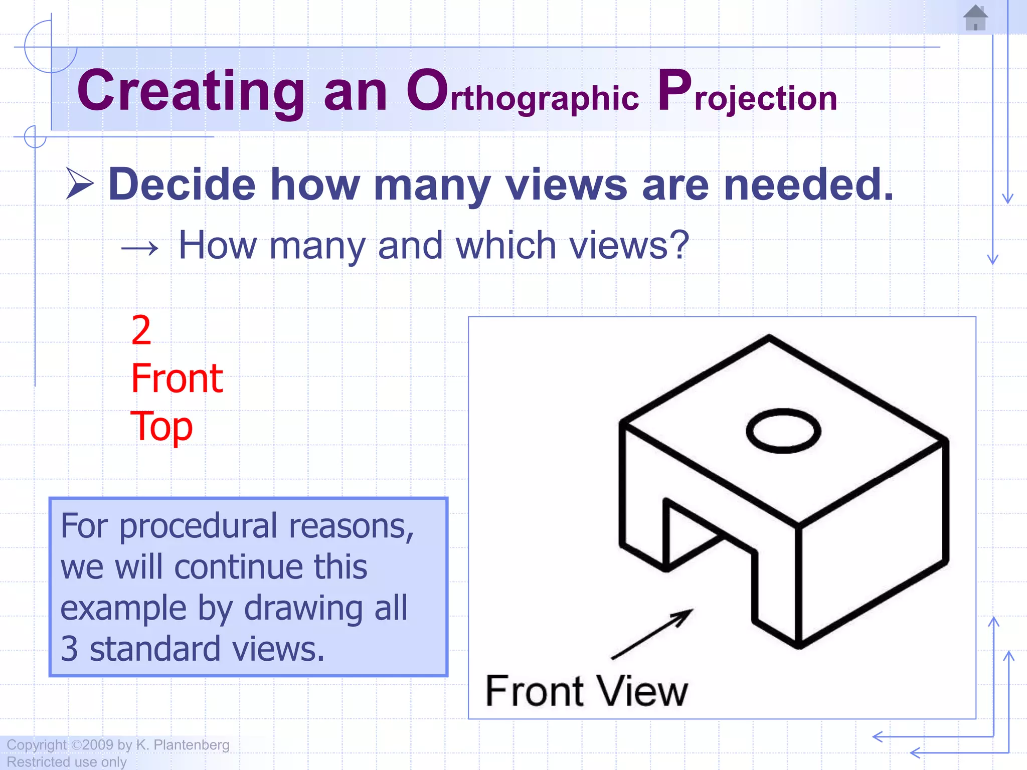
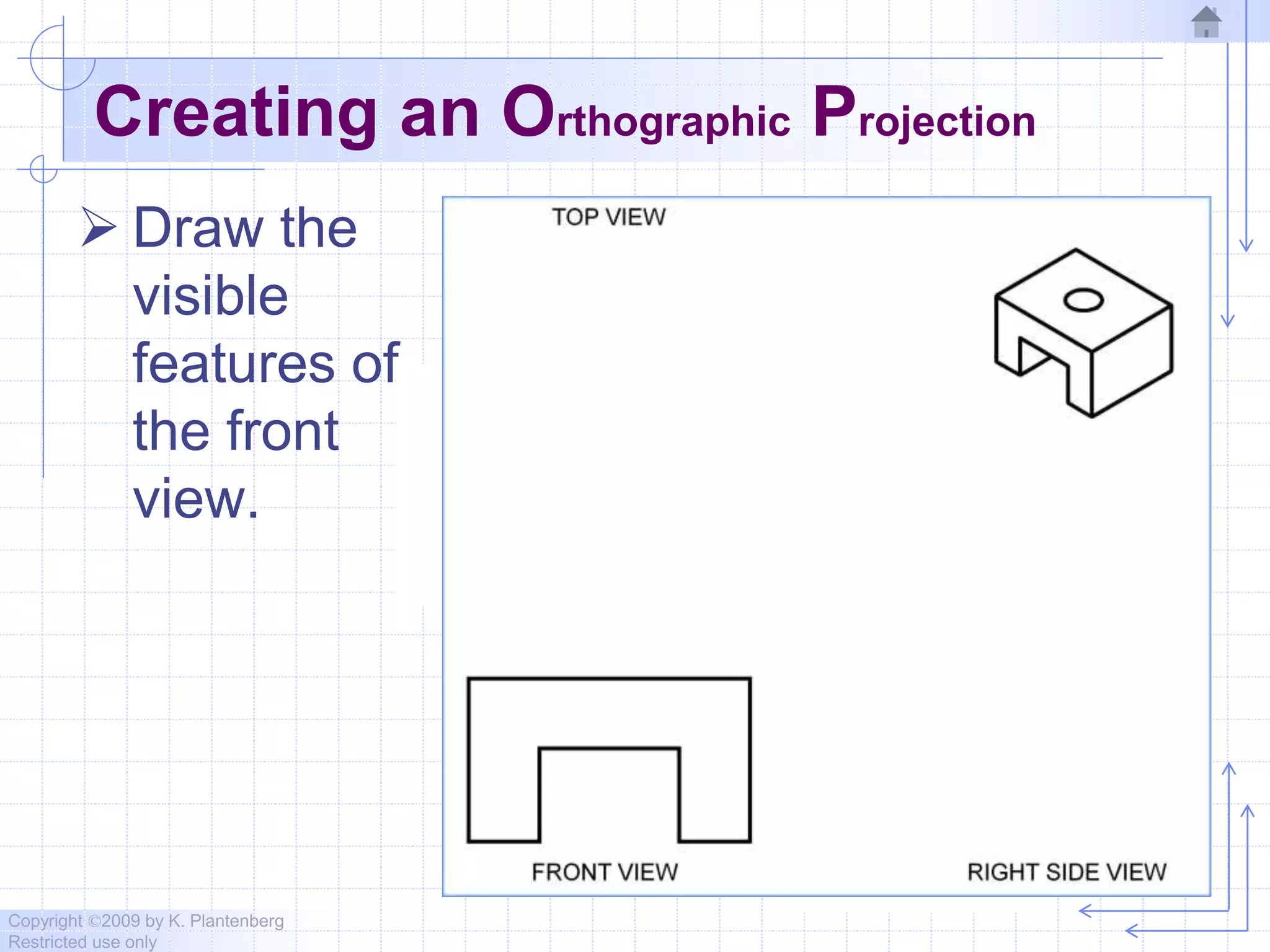
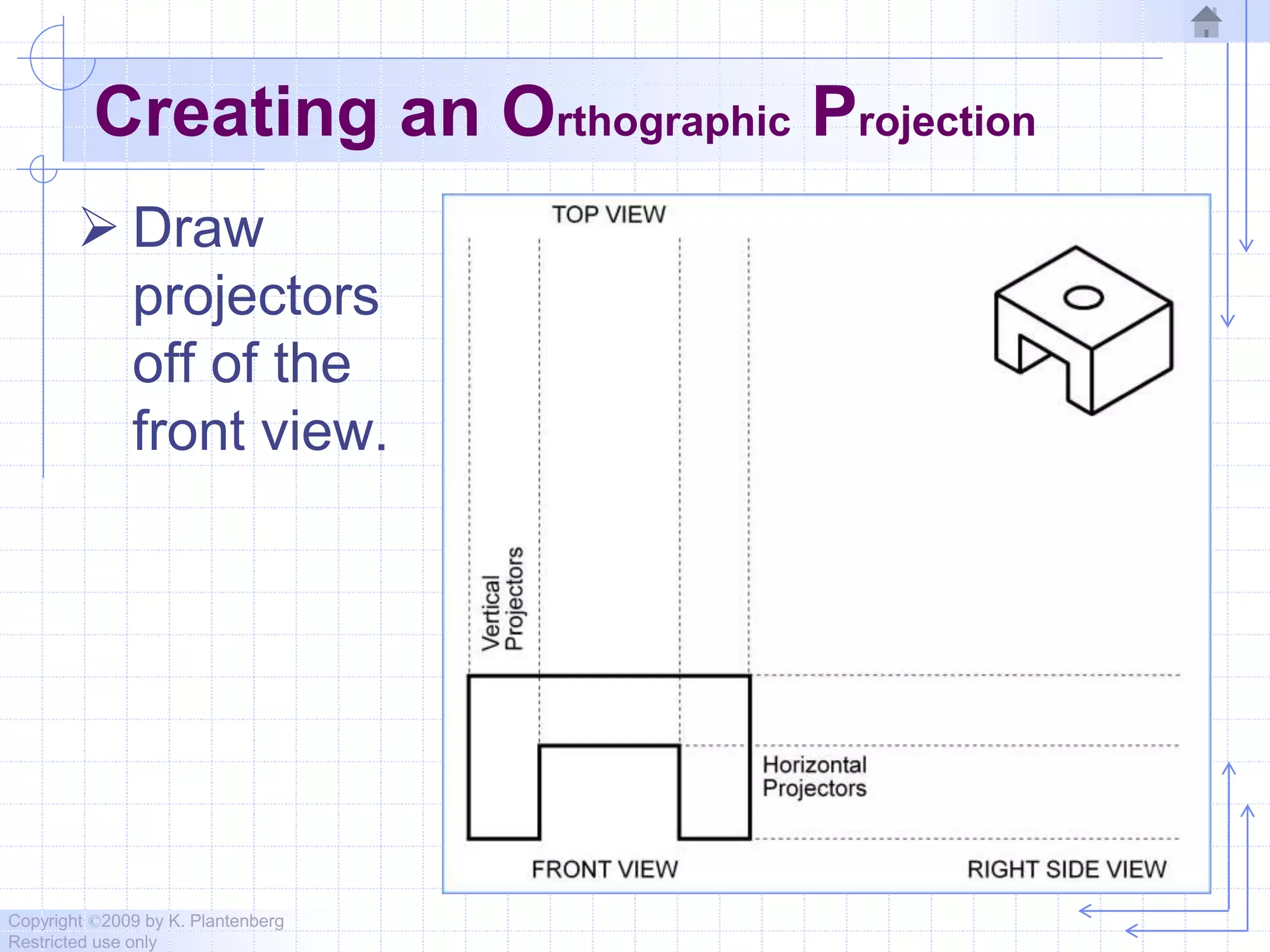
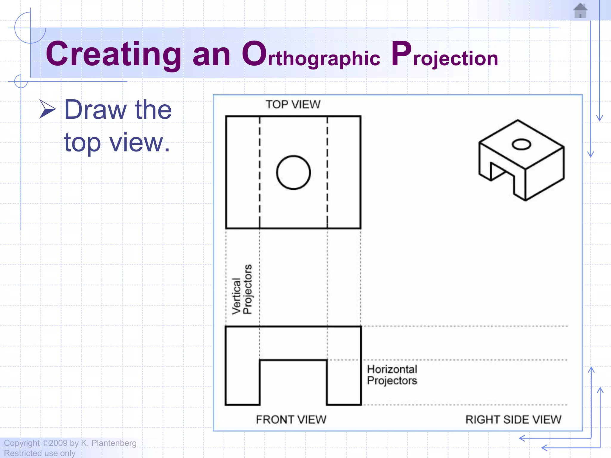
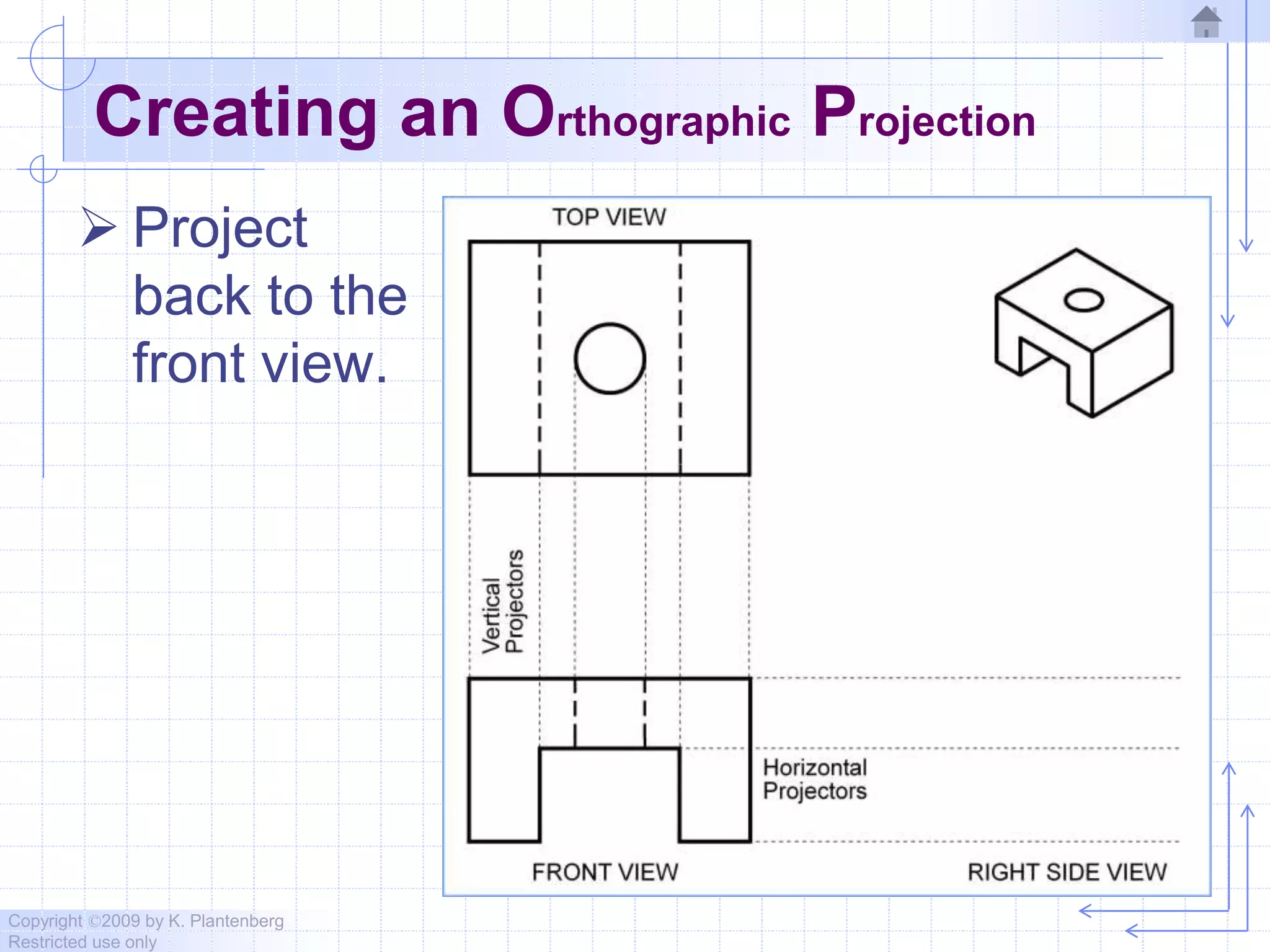
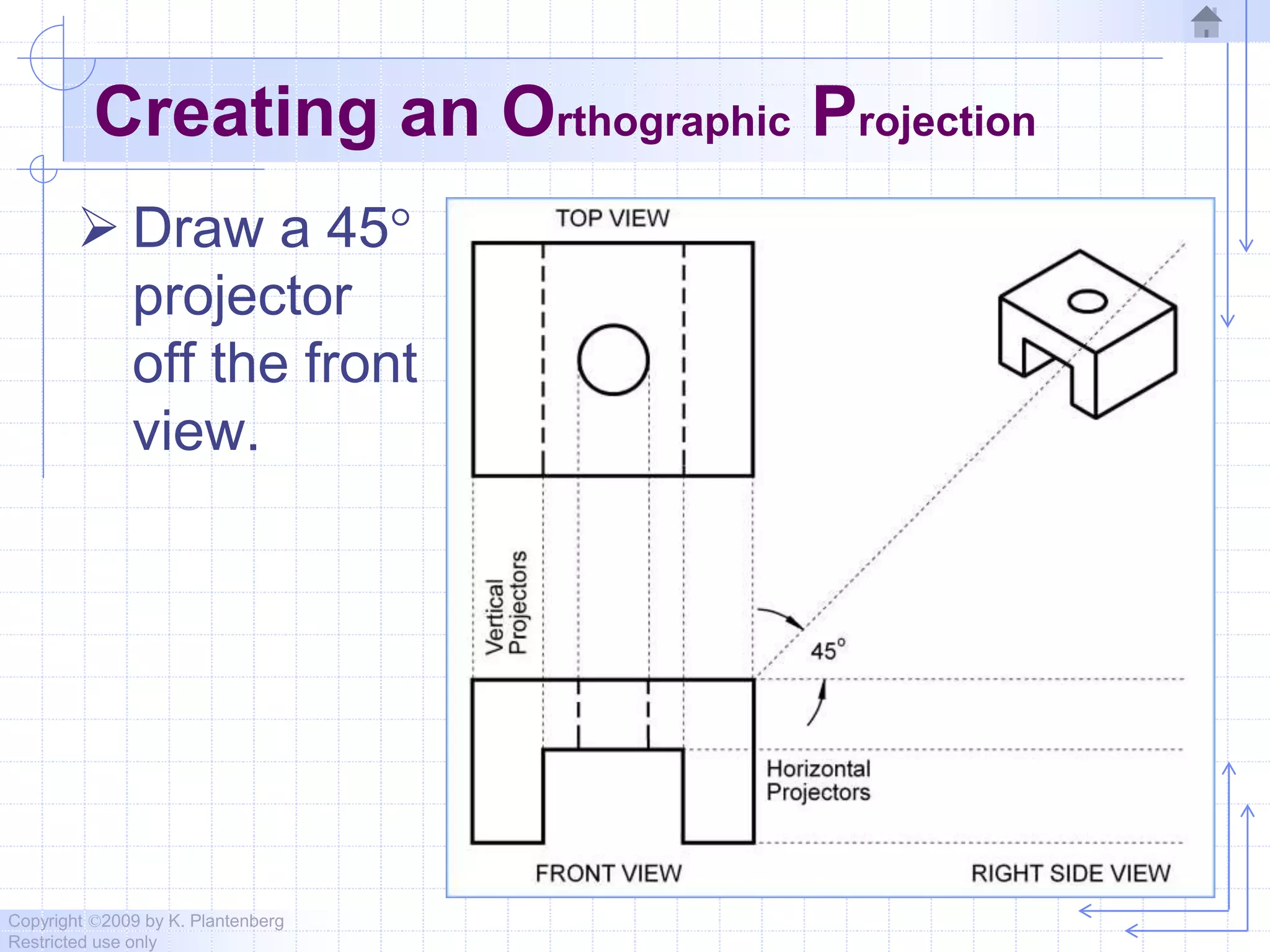
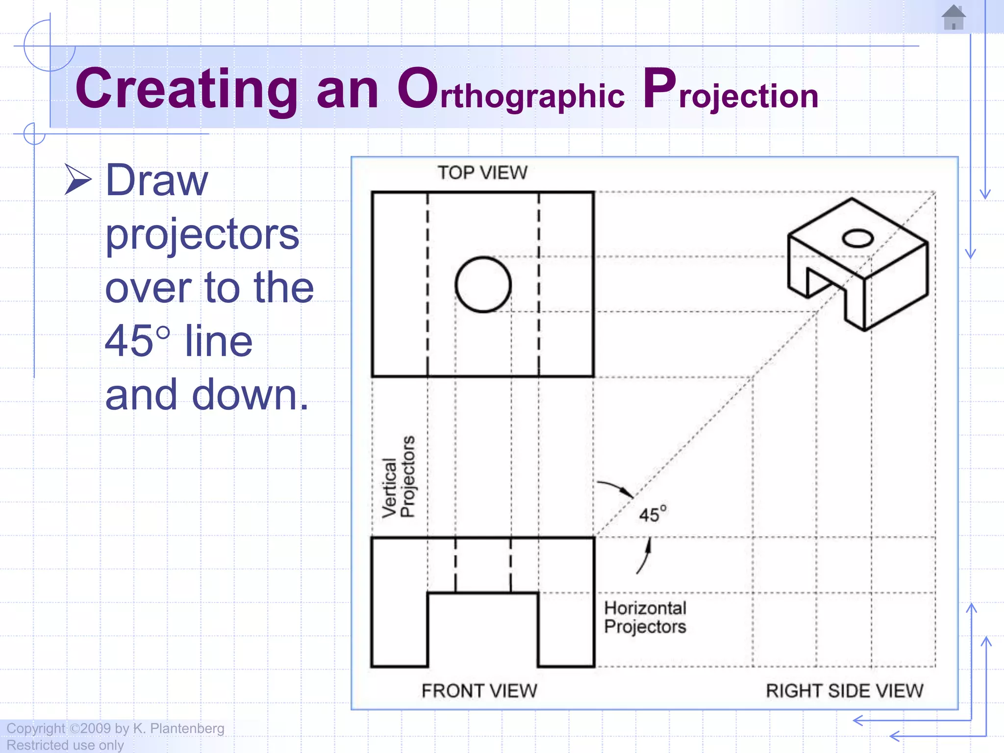
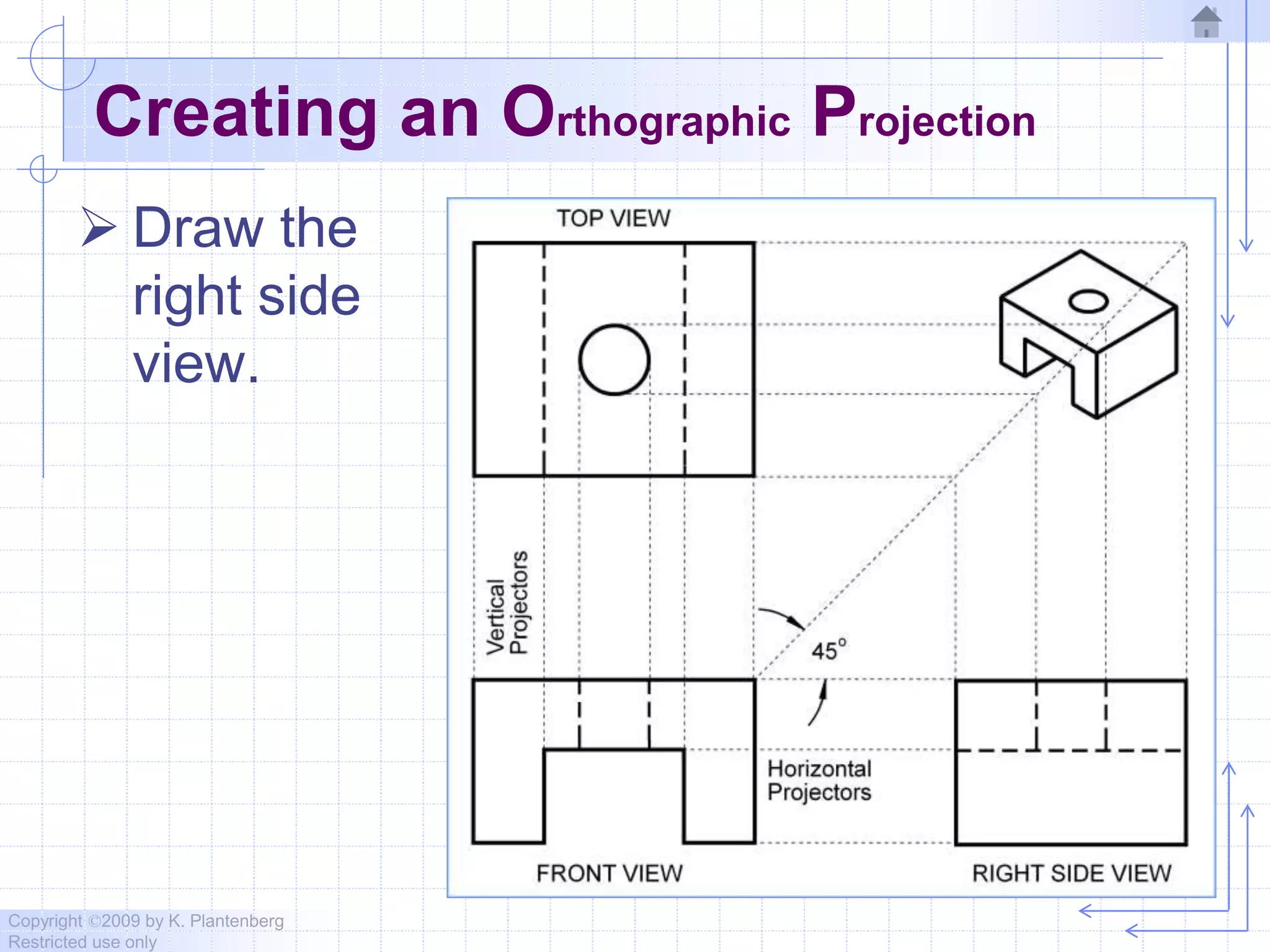
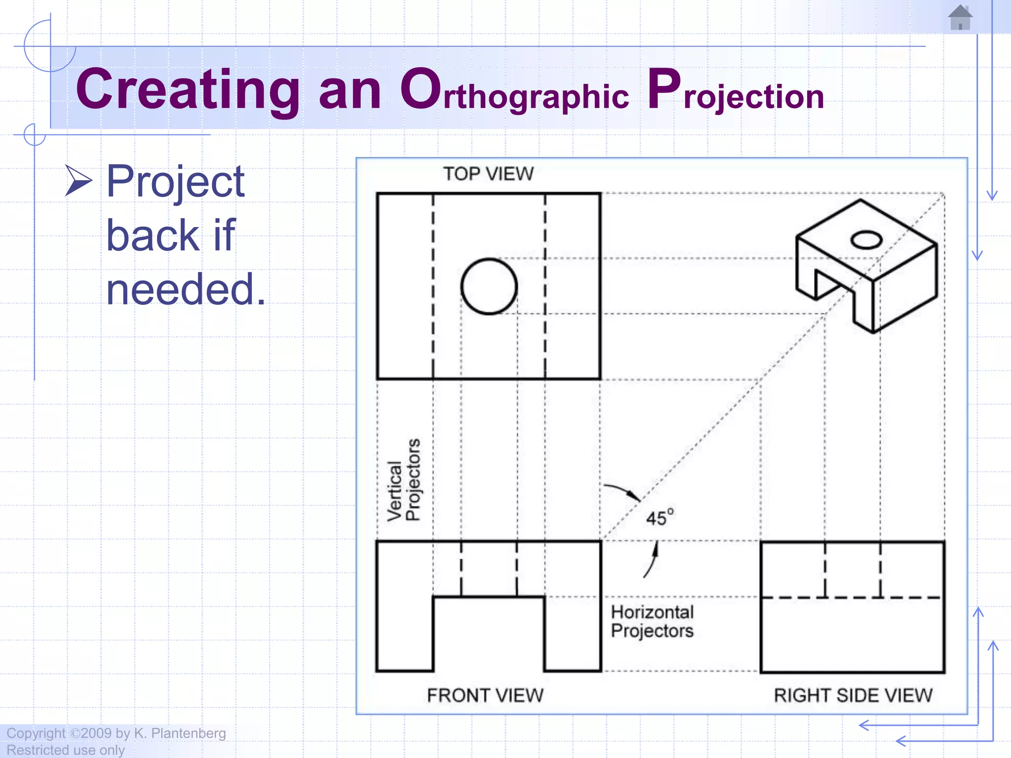
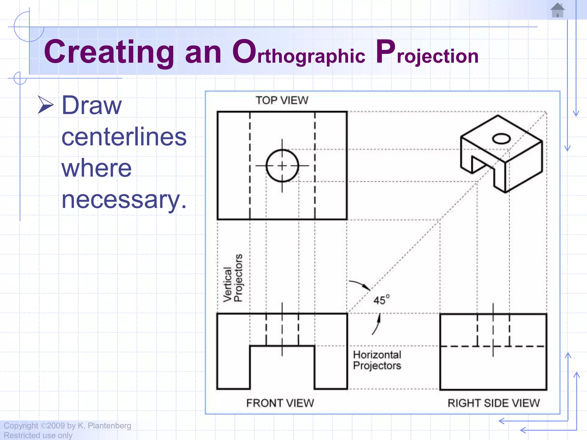
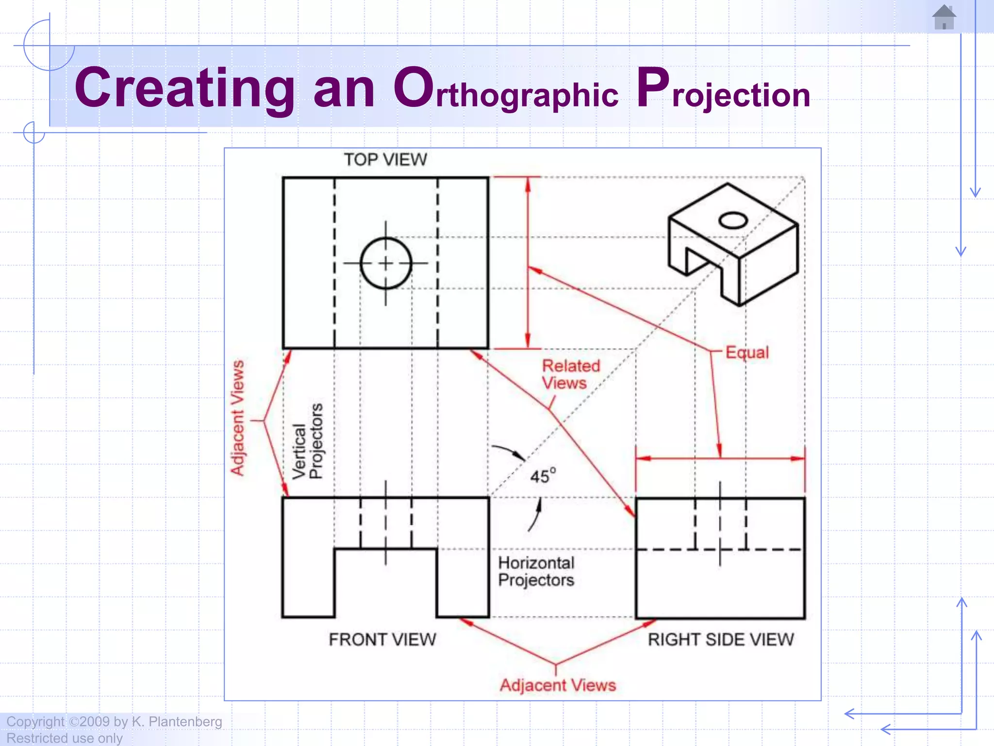
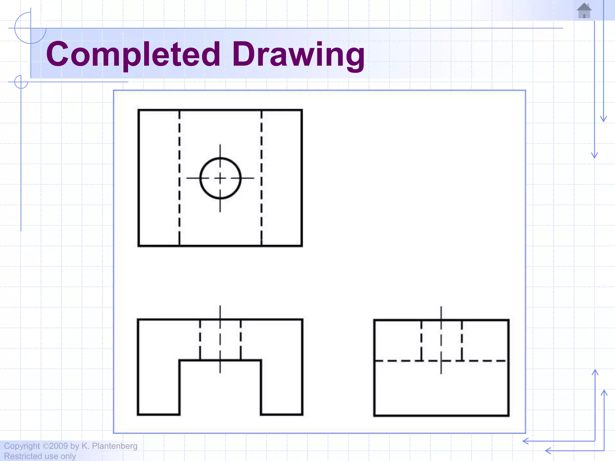
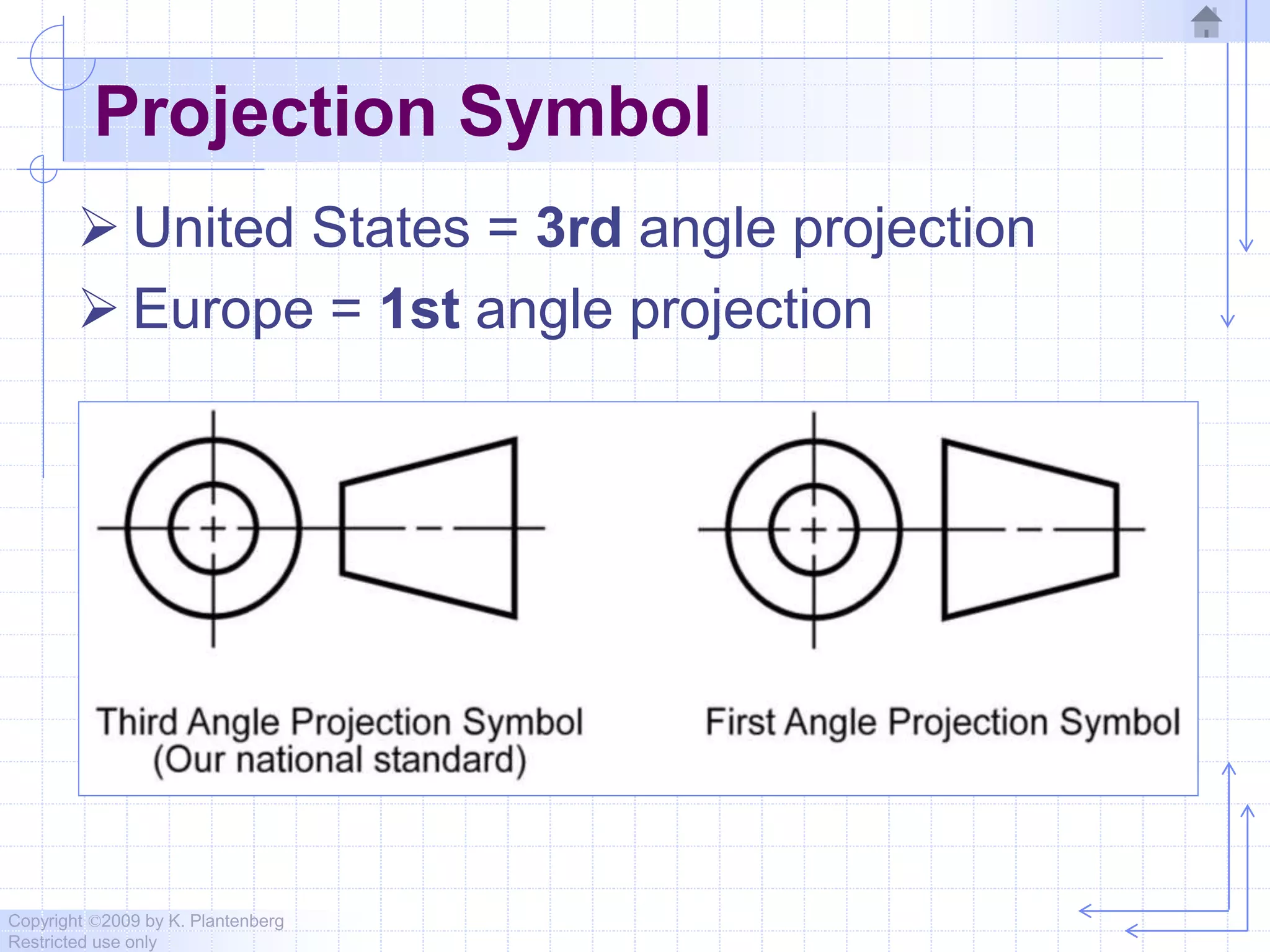
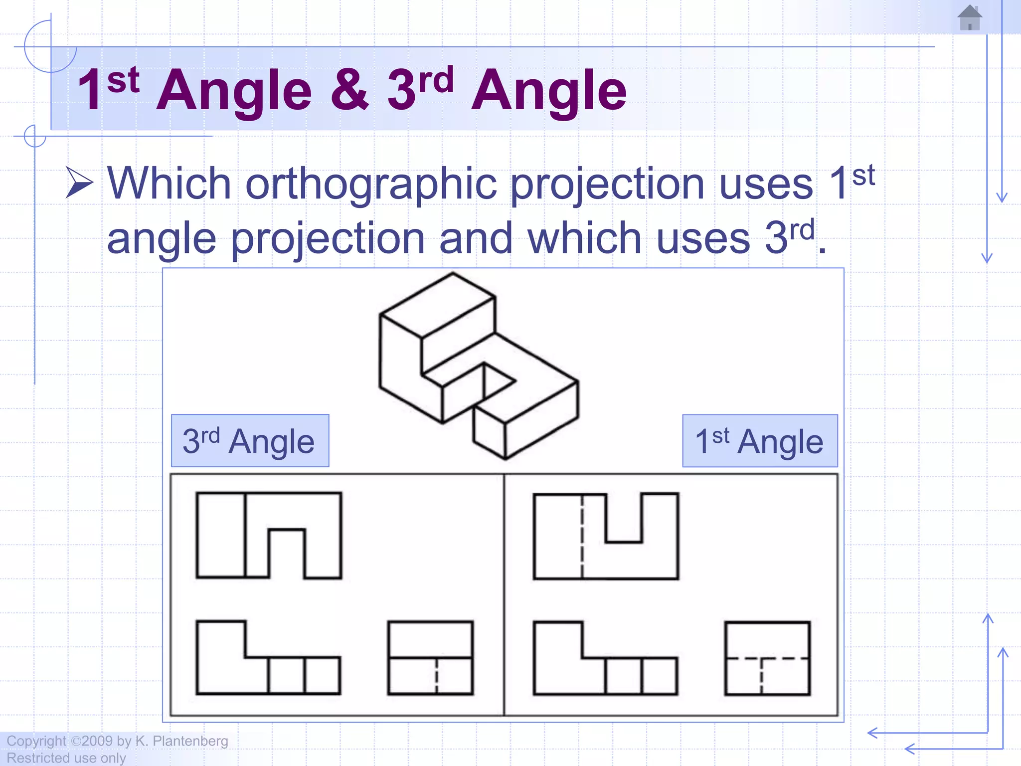
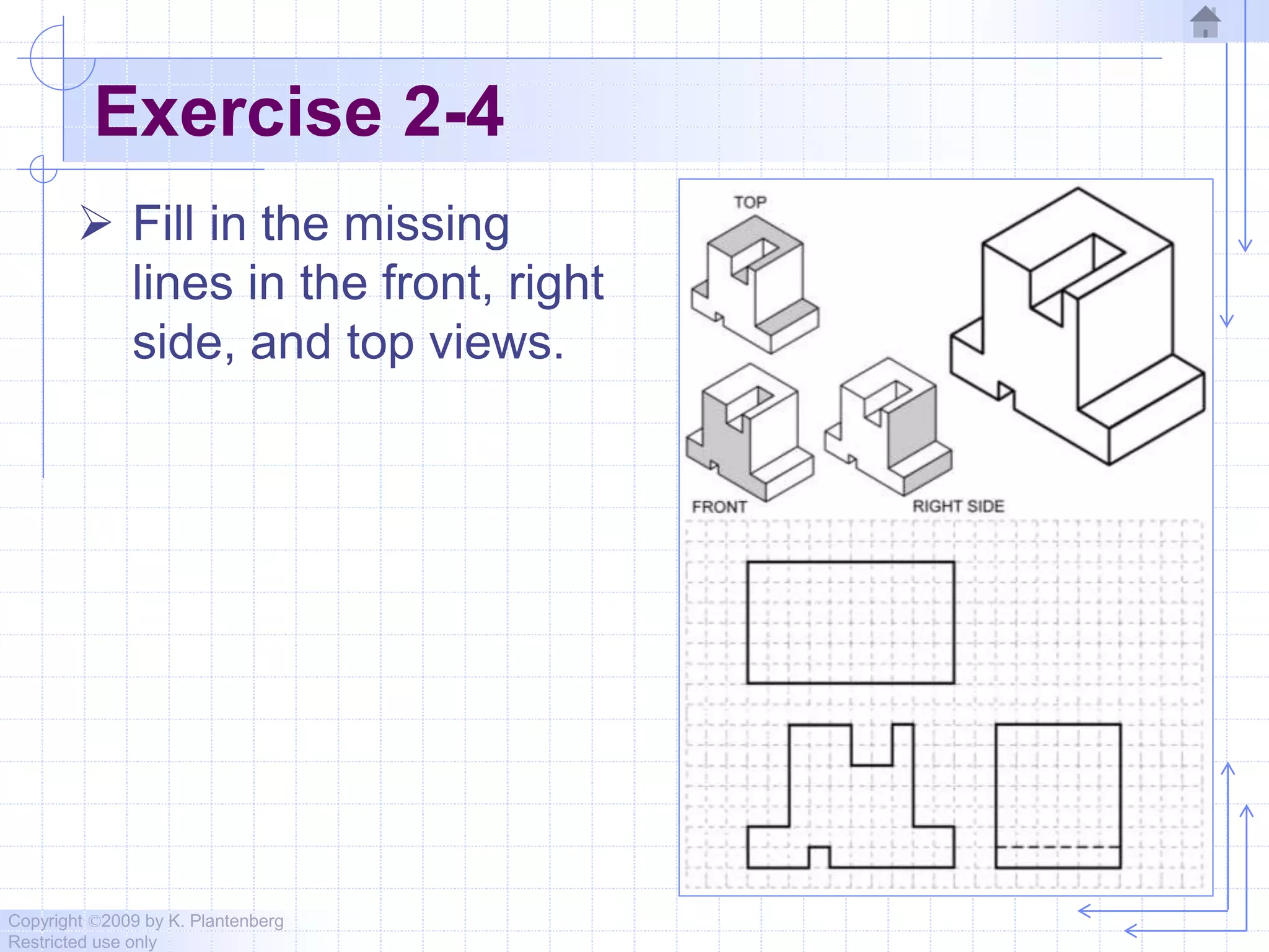
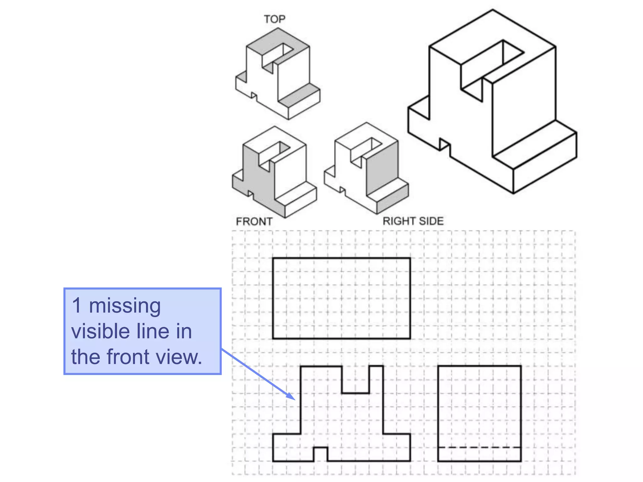
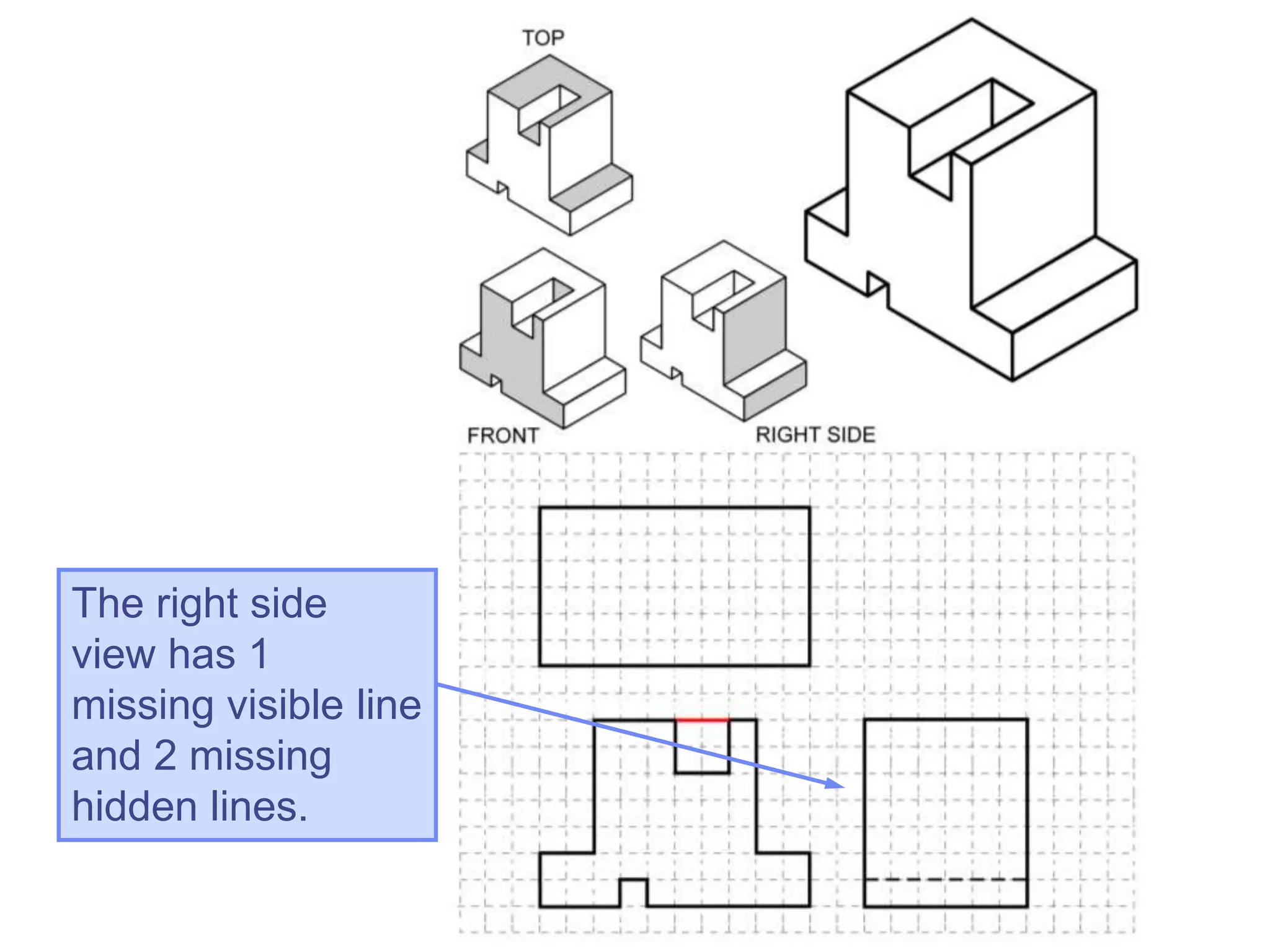
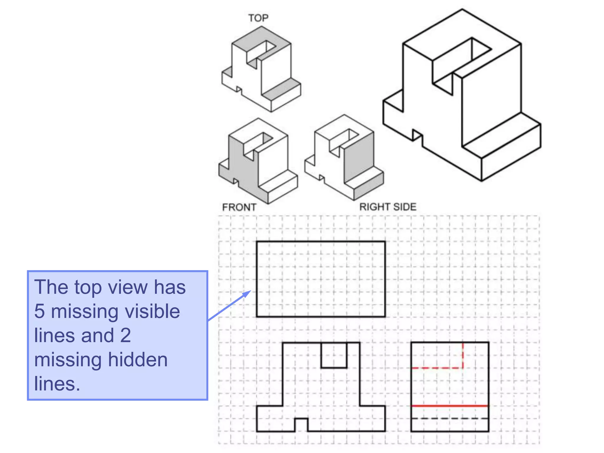


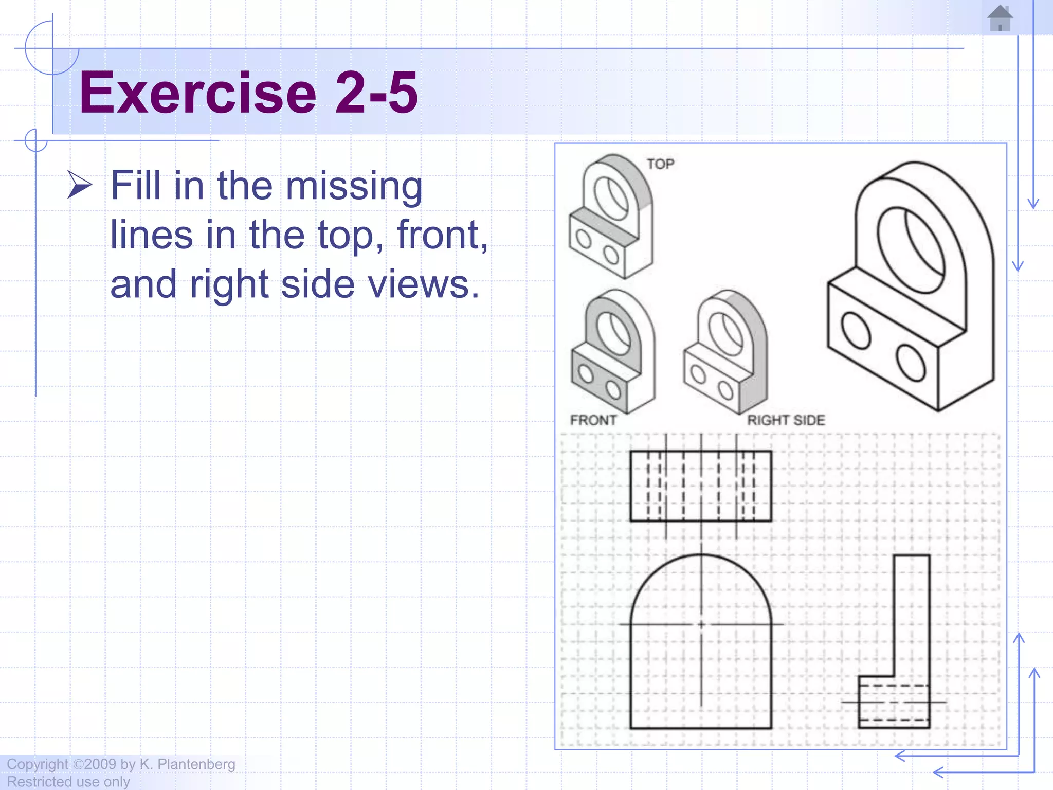
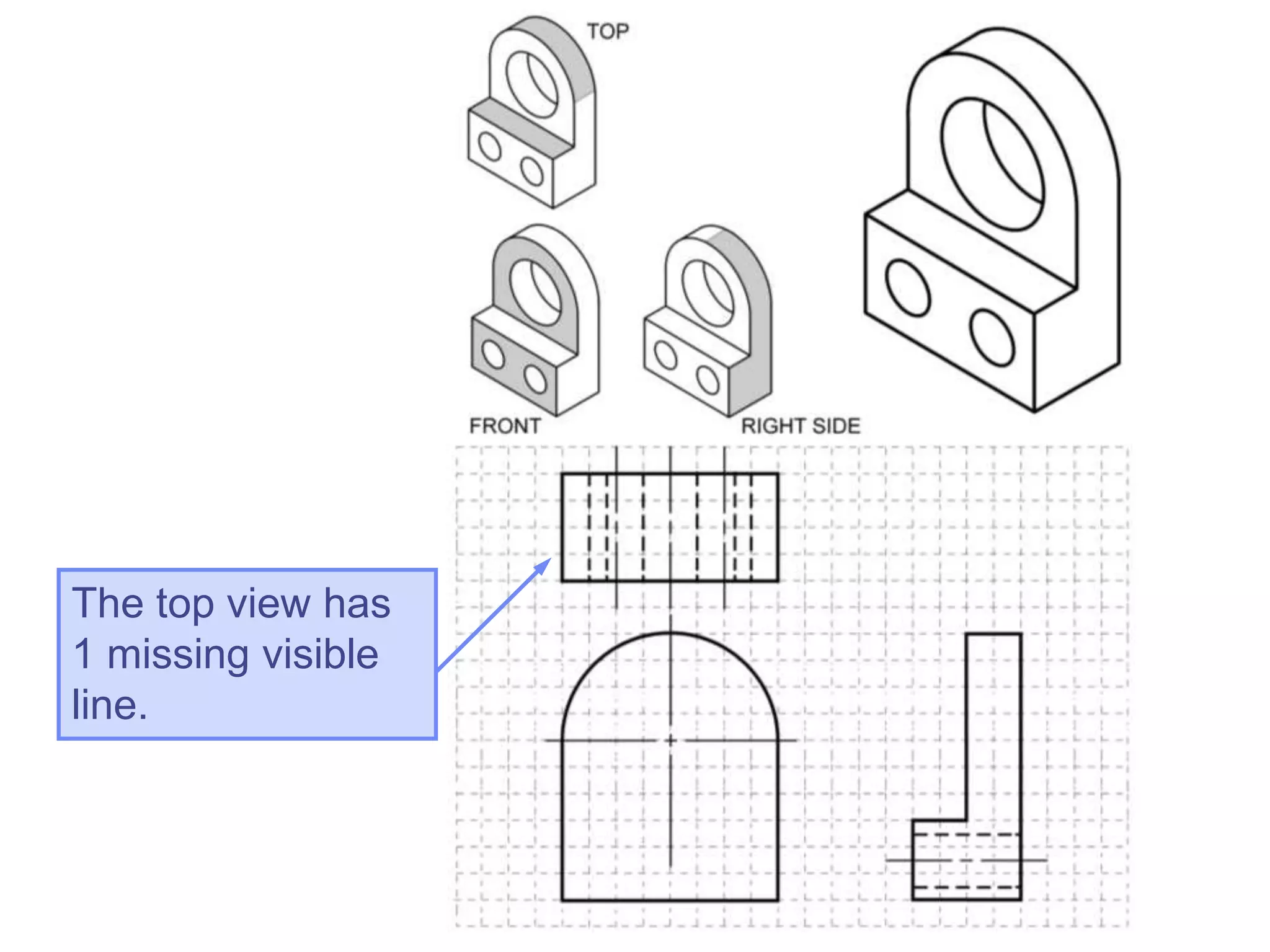
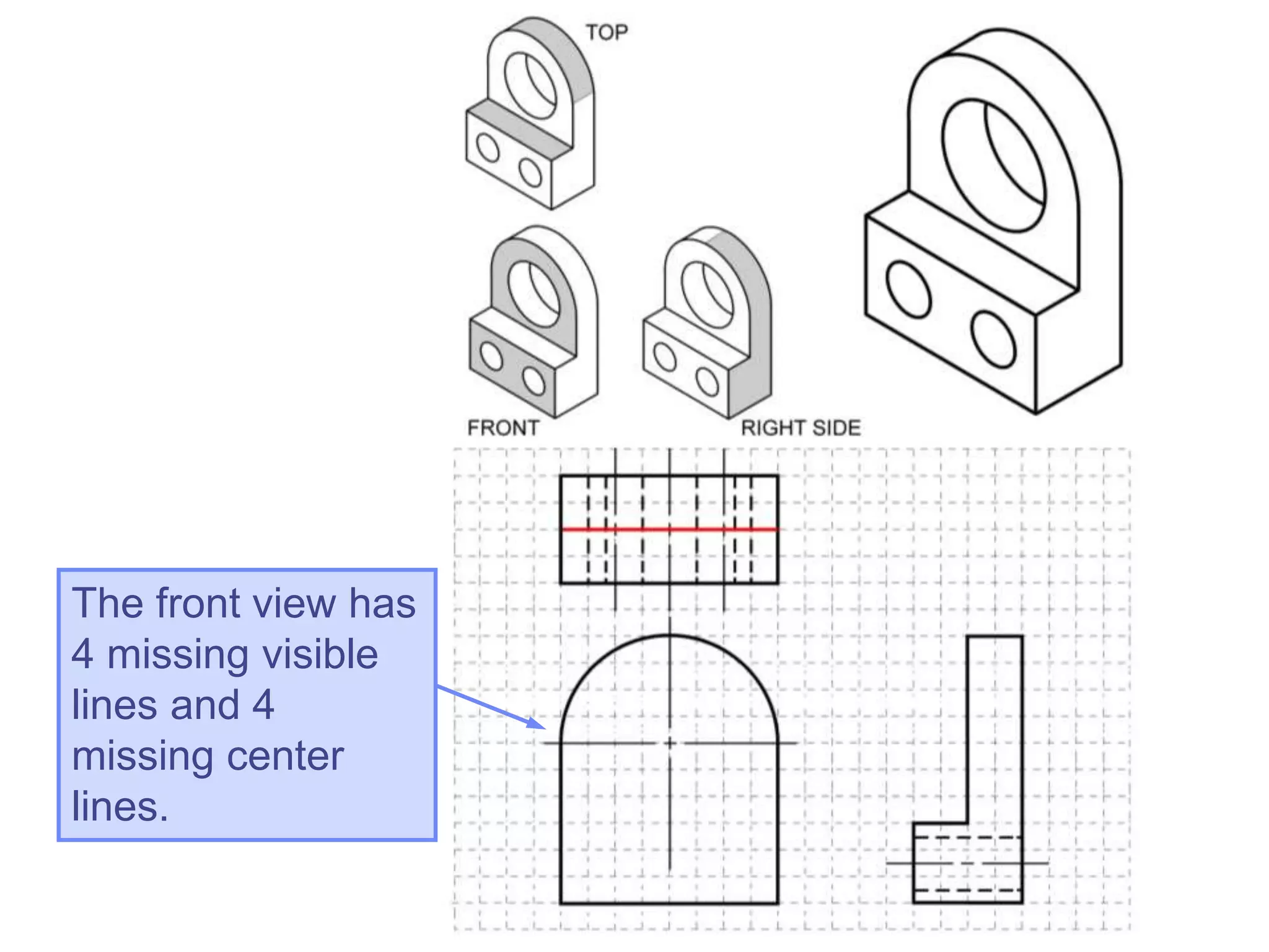
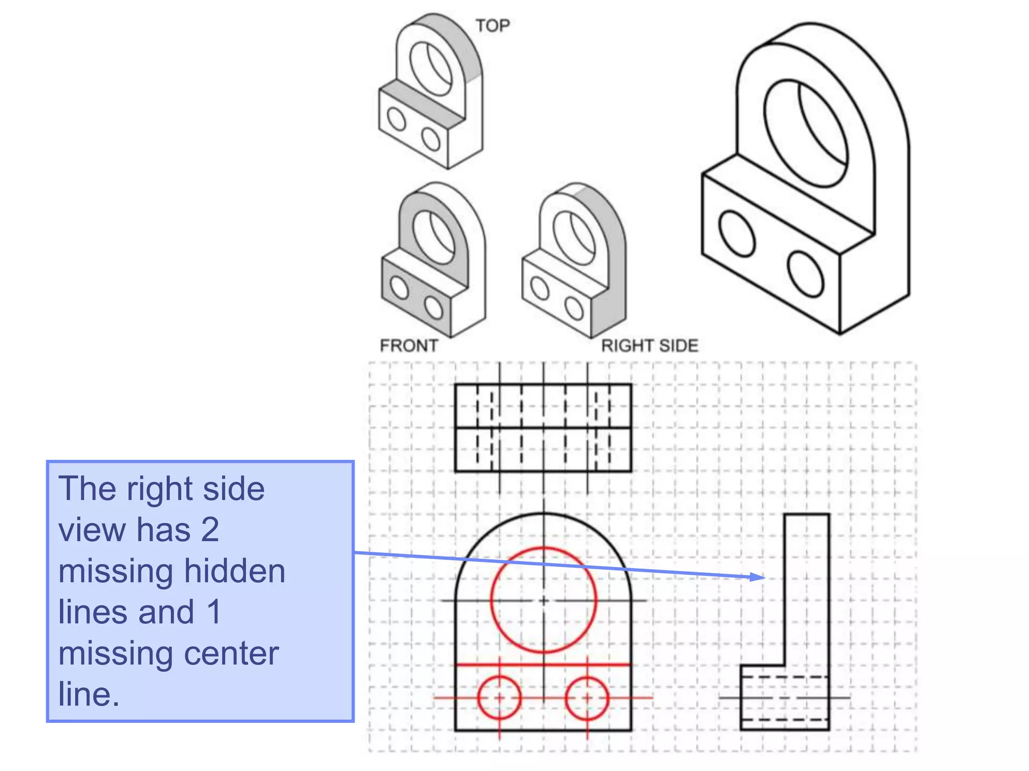
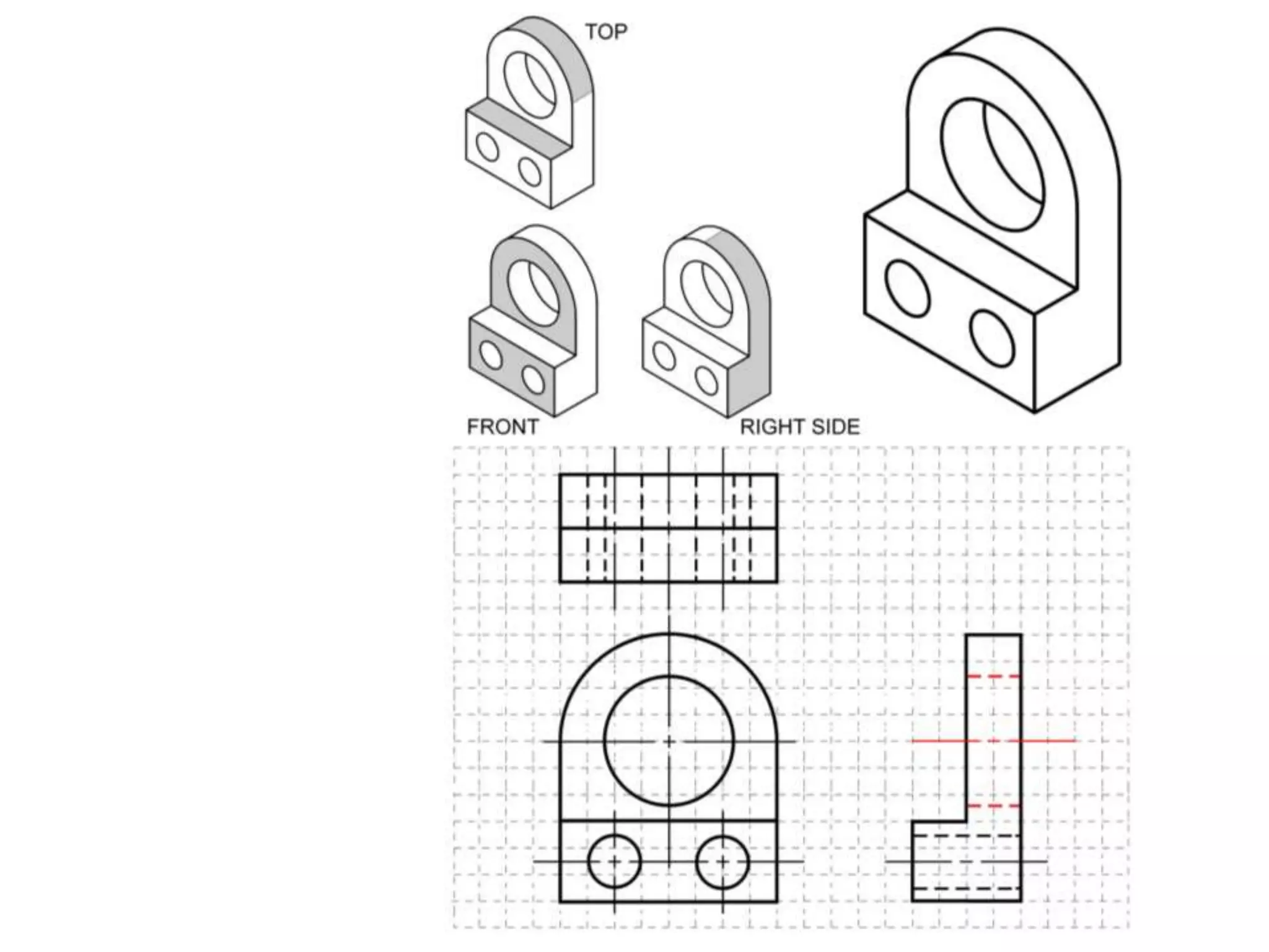
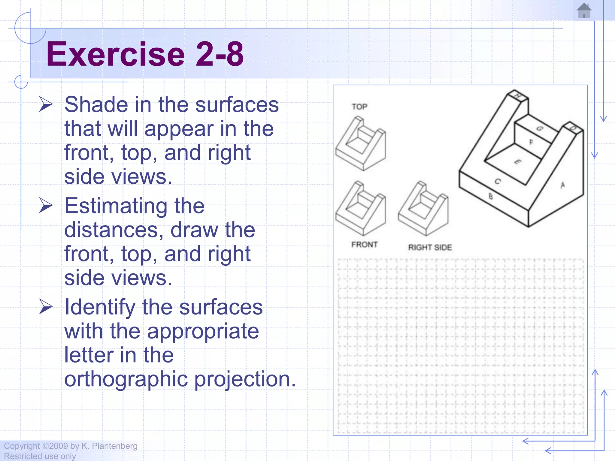
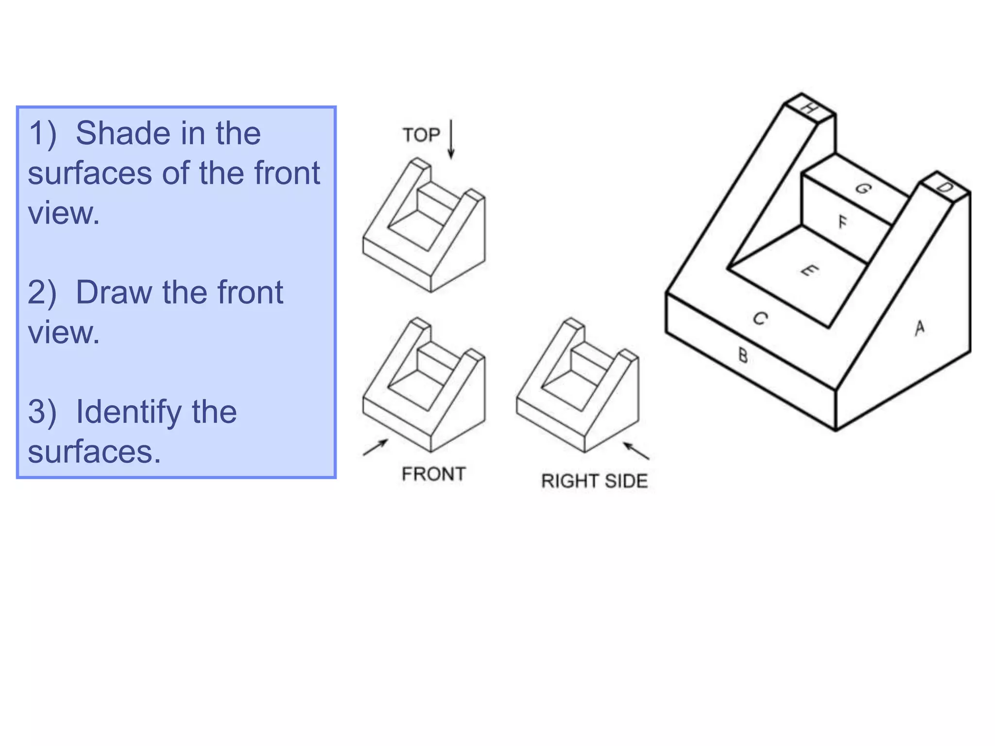
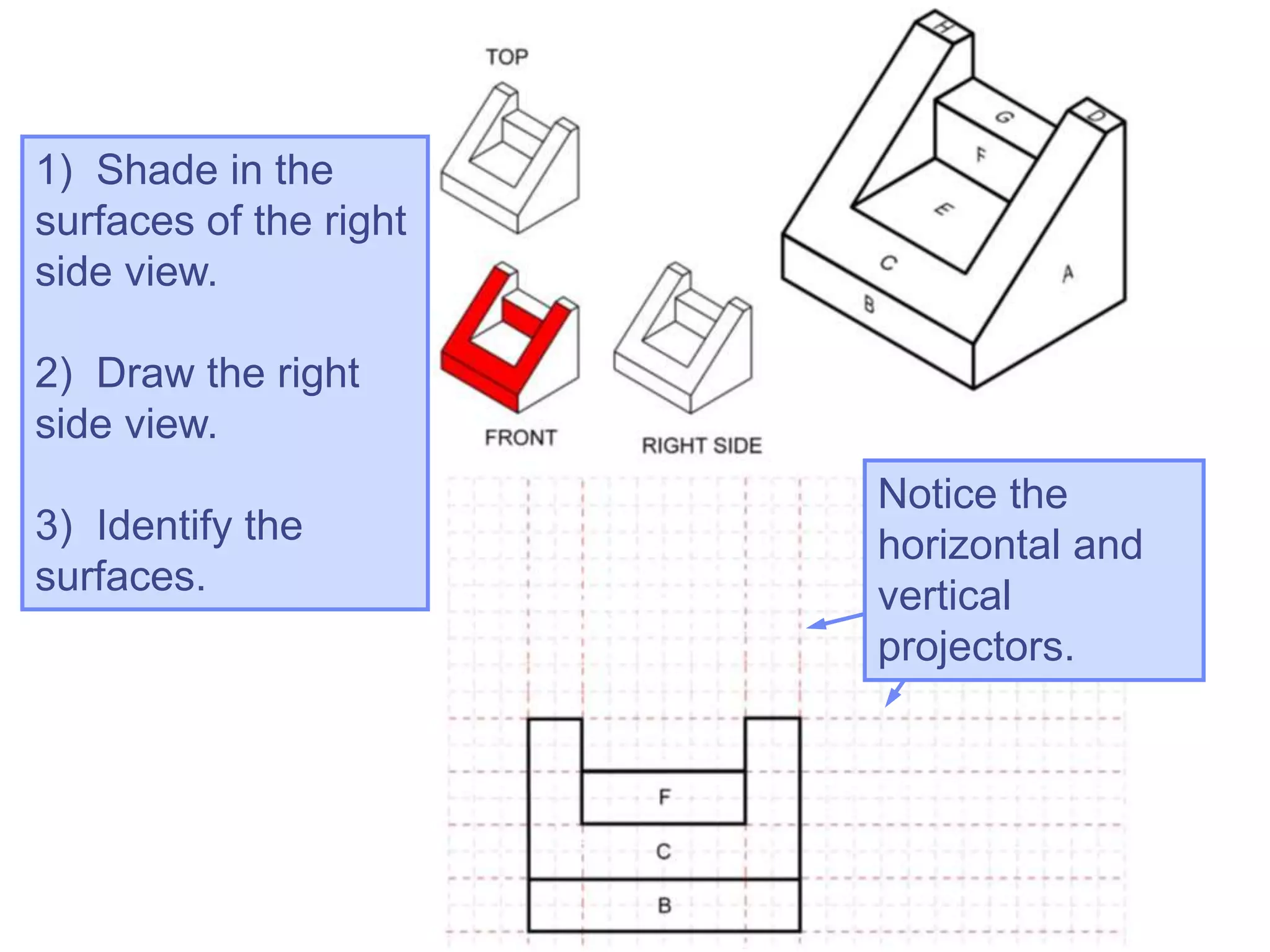
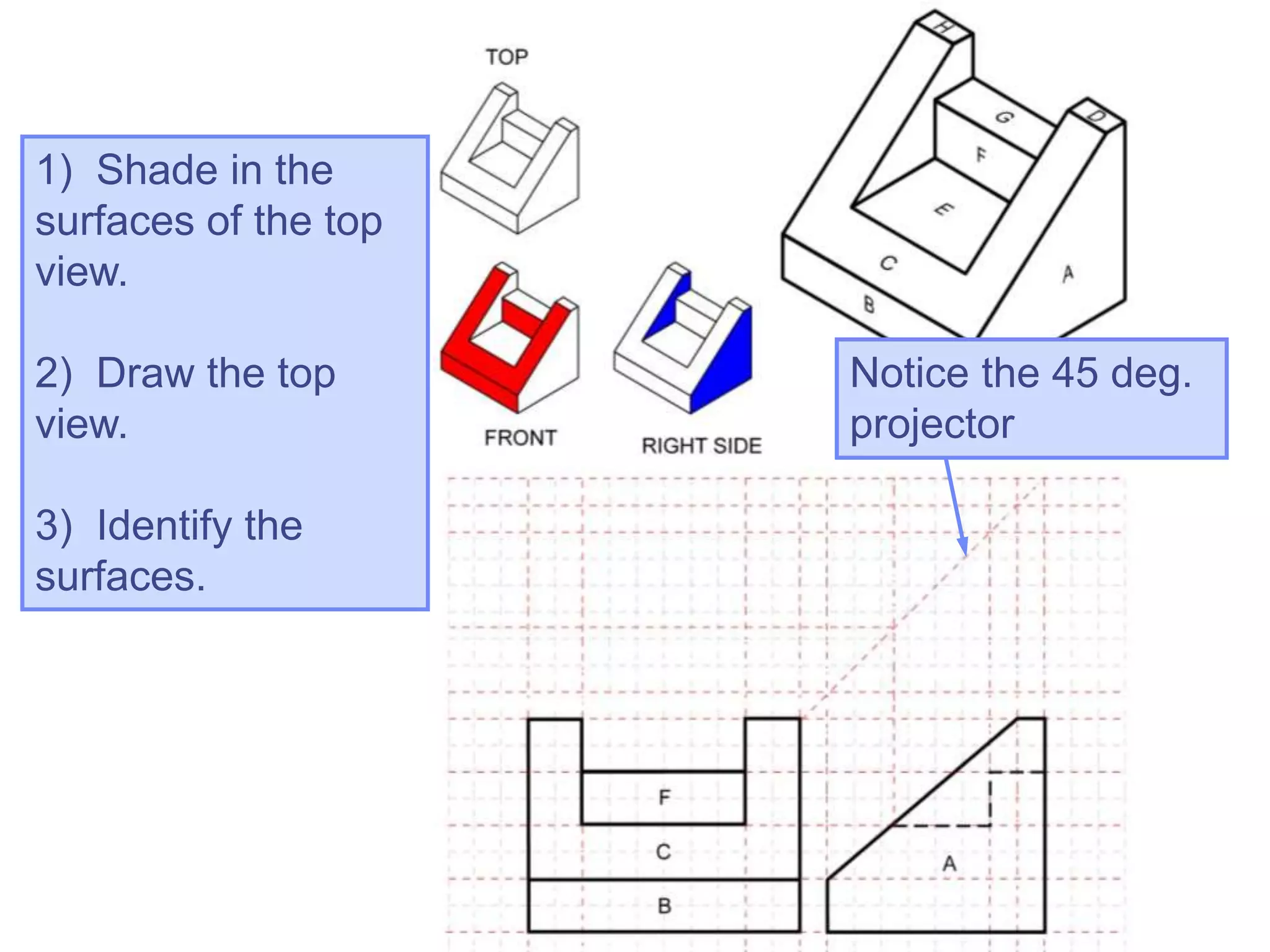
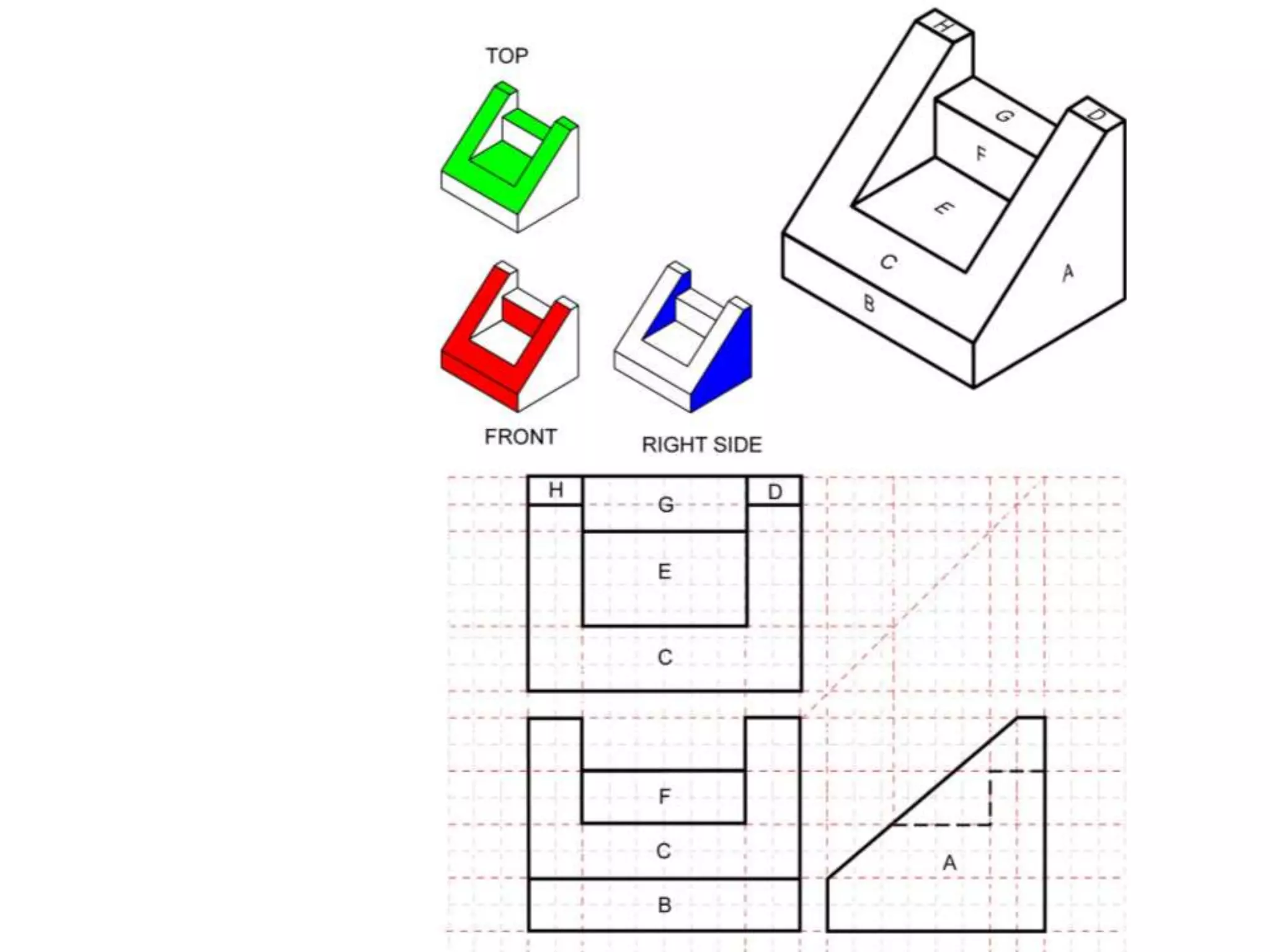
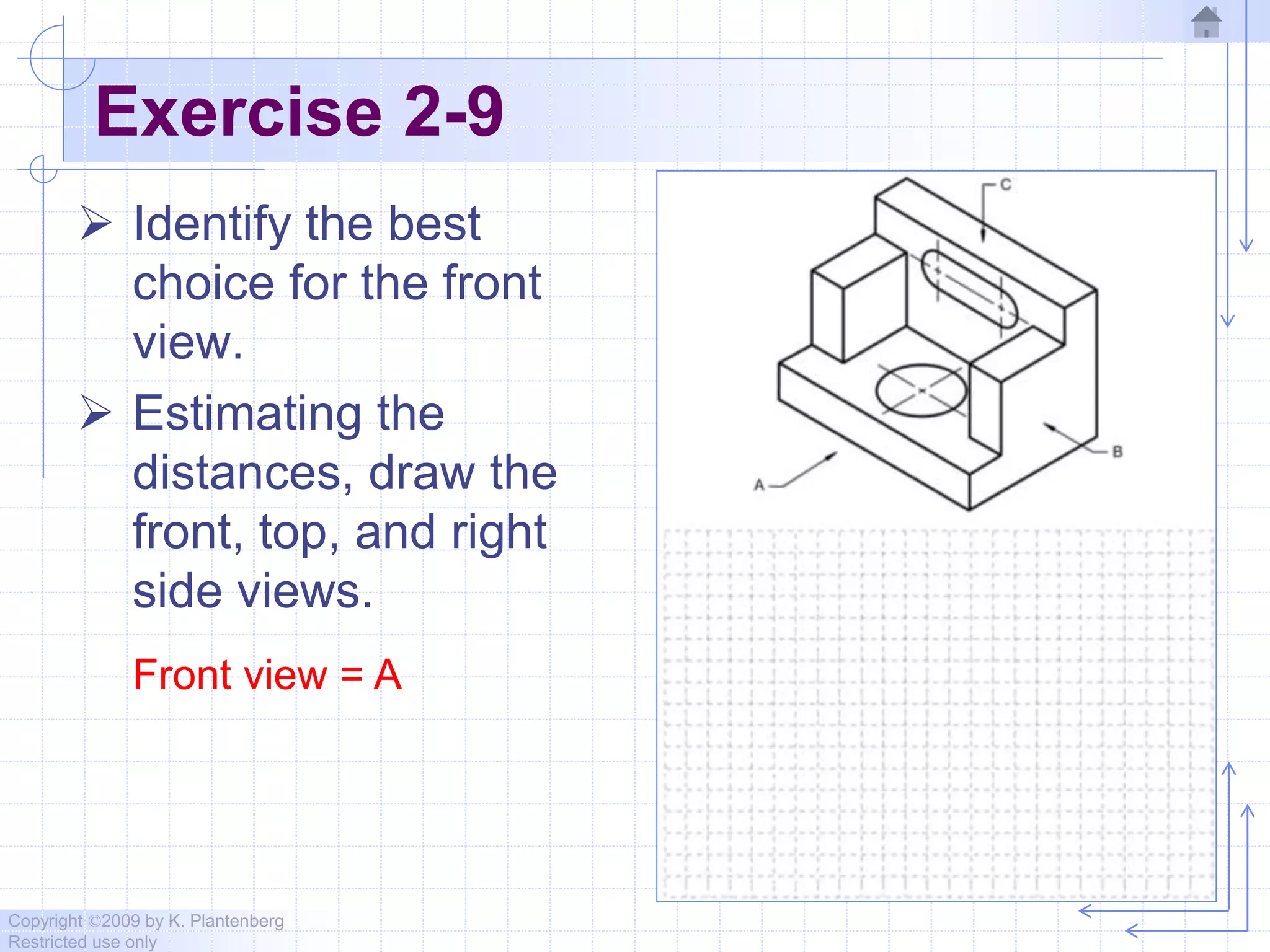
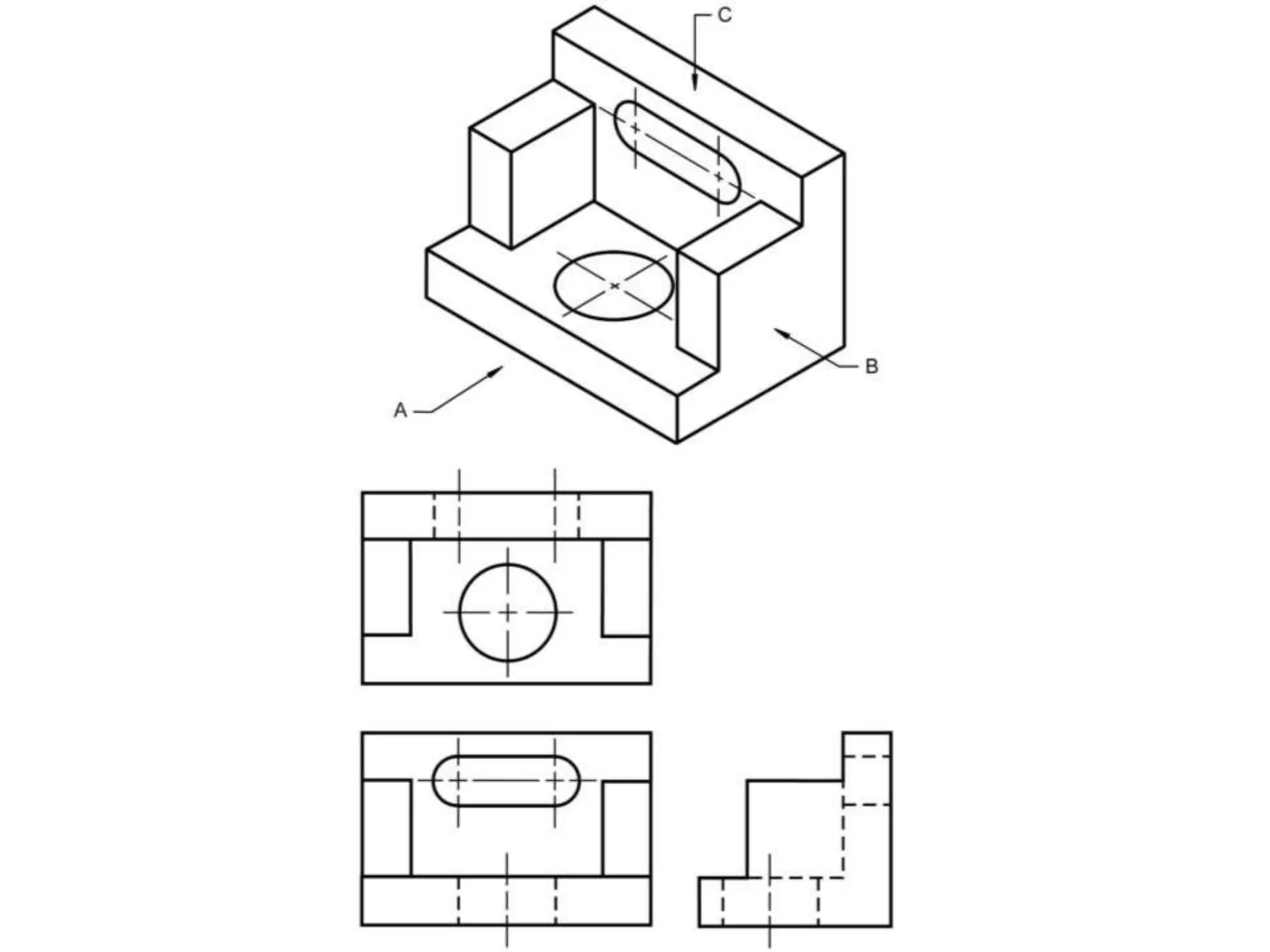
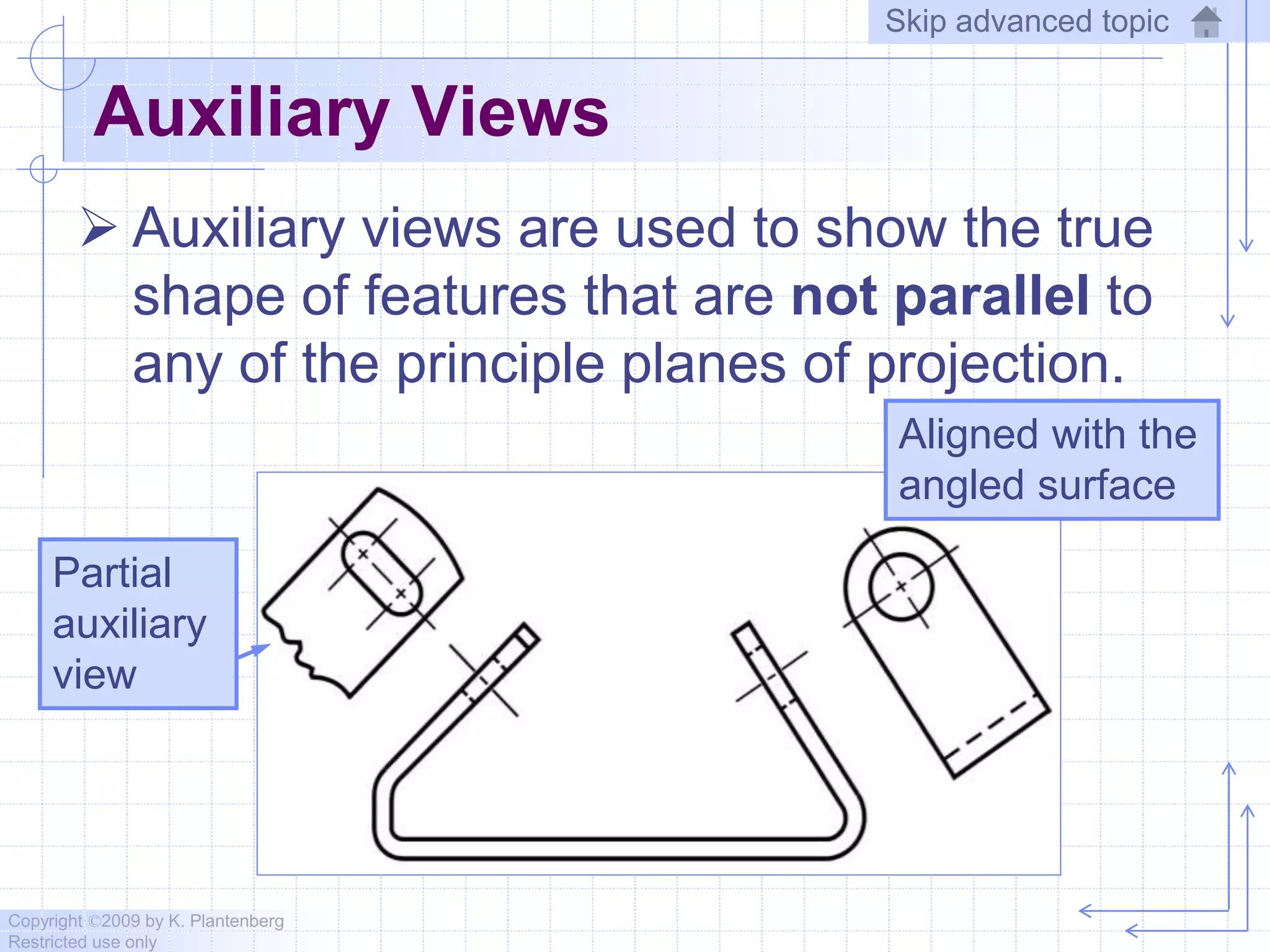

This document discusses orthographic projection and engineering graphics. It covers topics such as the glass box method for creating orthographic views, standard views used in projections, and different line types like visible, hidden, and center lines. Exercises are provided to help learn orthographic projections and identify line types. The document is copyrighted and for restricted use only.