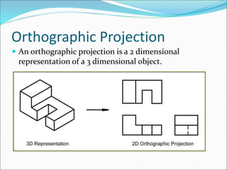
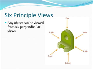
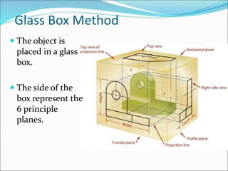
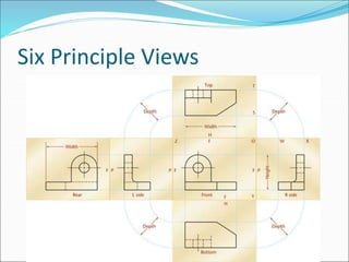
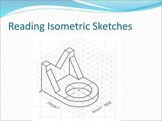
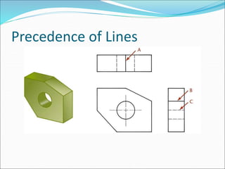
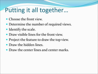
Orthographic Projection
 An orthographic projection is a 2 dimensional
representation of a 3 dimensional object.
Six Principle Views
 Any object can be viewed
from six perpendicular
views
The Glass Box
 One way to understand the standard arrangement of
views on a sheet of paper is to envision the object in a
glass box
 The outside observer would see six standard views of
the object through the sides of this imaginary glass box
Glass Box Method
 Glass Box Method:
 The object is placed in a glass box.
 The image of the object is projected on the sides of the
box.
 The box is unfolded.
 The sides of the box are the principle views.
Glass Box Method
 The object is
placed in a glass
box.
 The side of the
box represent the
6 principle
planes.
Six Principle Views
Reading Isometric Sketches
Create the orthographic projections for the
following object.
The height and depth of
is equal to 3 grid squares.
Create the orthographic projections for the
following object.
Number of Required Views
 When drawing an orthographic projection you must
include the appropriate number of views to fully
describe the true shape of the part.
 You may use a fewer number of views if you can fully
describe the part in the given views.
 How many views are required to fully describe a
rectangular box?
 How many views are required to fully describe a sphere?
Number of Required Views
 You may use additional views, such as the left, back,
or bottom views to describe an object if the object
cannot be fully described in the three standard views.
 additional views such as section views, detail views and
auxiliary views may also be drawn to fi.
Measurement Transfer Between Views
 Top and Bottom
views show LENGTH
and WIDTH.
 Left and Right views
show HEIGHT and
WIDTH
 Front and Rear views
show HEIGHT and
LENGTH.
 The line (drawn at a
45° angle) is used to
transfer depth
measurements
between the top and
right side (or left
side) views.
Normal Plane
 Normal Planes
will appear as an
edge in two views
and a true sized
plan in the
remaining view
when using three
views such as a
top, front and
right side.
Inclined Plane
 Inclined Planes
will appear as an
edge view in only
one of the three
views.
 The inclined
plane will appear
as a rectangular
surface in the
other two views.
Oblique Planes
 Oblique Planes will
not appear as an
edge view in any of
the six views since
they are not parallel
or perpendicular to
the projection
planes.
 They always appear
as a “plane” and have
the same number of
corners in each of
the six views.
Foreshortened Lines
Identify the foreshortened
lines in the orthographic
projection below.
Curved Surfaces
 A cylinder
will appear
as a circle in
one view
and a
rectangular
shape the
other two
views.
Axis and Center Lines
 The axis appears
where the cylinder
appears
rectangular.
 Center marks are
used to identify
the center of the
cylinder where it
appears circular.
Choosing the Front View
 Considerations when choosing the front view of an
object.
 Chose the view that shows the most features or
characteristics of the object
 Choose the view that contains the least number of
hidden lines.
 Choose the view so the part is oriented with its longest
length parallel to the bottom of the drawing.
First- and Third-Angle Projection
 There are two main systems used for projecting and
unfolding the views:
 Third-angle projection which is used in the United
States, Canada and some other countries
 First-angle projection which is primarily used in Europe
and Asia
 You should understand both methods
Third-angle Projection
First-angle Projection
Hidden Lines
 An advantage of orthographic views is that each view
shows the object all the way through as if it were
transparent
 Thick dark lines represent visible features
 Dashed lines represent features that would be hidden
behind other surfaces
 When possible, choose views that show features with
visible lines
 Rules for drawing hidden lines.
Centerlines
 The centerline is used to:
 Show the axis of symmetry of a feature or part
 Indicate a path of motion
 Show the location for bolt circles or other circular
patterns
 The centerline pattern is composed of three dashes,
one long dash on each end with a short dash in the
middle
Centerlines
Precedence of Lines
 When lines coincide on a drawing the rules of
precedence are:
 Visible lines always take precedence over hidden or
centerlines
 Hidden lines take precedence over centerlines
Precedence of Lines
Putting it all together…
 Choose the front view.
 Determine the number of required views.
 Identify the scale.
 Draw visible lines for the front view.
 Project the feature to draw the top view.
 Draw the hidden lines.
 Draw the center lines and center marks.

Lecture 4 (CED).ppt

  • 2.
    Orthographic Projection  Anorthographic projection is a 2 dimensional representation of a 3 dimensional object.
  • 3.
    Six Principle Views Any object can be viewed from six perpendicular views
  • 4.
    The Glass Box One way to understand the standard arrangement of views on a sheet of paper is to envision the object in a glass box  The outside observer would see six standard views of the object through the sides of this imaginary glass box
  • 5.
    Glass Box Method Glass Box Method:  The object is placed in a glass box.  The image of the object is projected on the sides of the box.  The box is unfolded.  The sides of the box are the principle views.
  • 6.
    Glass Box Method The object is placed in a glass box.  The side of the box represent the 6 principle planes.
  • 7.
  • 8.
  • 9.
  • 10.
    Create the orthographicprojections for the following object. The height and depth of is equal to 3 grid squares.
  • 11.
    Create the orthographicprojections for the following object.
  • 12.
    Number of RequiredViews  When drawing an orthographic projection you must include the appropriate number of views to fully describe the true shape of the part.  You may use a fewer number of views if you can fully describe the part in the given views.  How many views are required to fully describe a rectangular box?  How many views are required to fully describe a sphere?
  • 13.
    Number of RequiredViews  You may use additional views, such as the left, back, or bottom views to describe an object if the object cannot be fully described in the three standard views.  additional views such as section views, detail views and auxiliary views may also be drawn to fi.
  • 14.
    Measurement Transfer BetweenViews  Top and Bottom views show LENGTH and WIDTH.  Left and Right views show HEIGHT and WIDTH  Front and Rear views show HEIGHT and LENGTH.  The line (drawn at a 45° angle) is used to transfer depth measurements between the top and right side (or left side) views.
  • 15.
    Normal Plane  NormalPlanes will appear as an edge in two views and a true sized plan in the remaining view when using three views such as a top, front and right side.
  • 16.
    Inclined Plane  InclinedPlanes will appear as an edge view in only one of the three views.  The inclined plane will appear as a rectangular surface in the other two views.
  • 17.
    Oblique Planes  ObliquePlanes will not appear as an edge view in any of the six views since they are not parallel or perpendicular to the projection planes.  They always appear as a “plane” and have the same number of corners in each of the six views.
  • 18.
    Foreshortened Lines Identify theforeshortened lines in the orthographic projection below.
  • 19.
    Curved Surfaces  Acylinder will appear as a circle in one view and a rectangular shape the other two views.
  • 20.
    Axis and CenterLines  The axis appears where the cylinder appears rectangular.  Center marks are used to identify the center of the cylinder where it appears circular.
  • 21.
    Choosing the FrontView  Considerations when choosing the front view of an object.  Chose the view that shows the most features or characteristics of the object  Choose the view that contains the least number of hidden lines.  Choose the view so the part is oriented with its longest length parallel to the bottom of the drawing.
  • 22.
    First- and Third-AngleProjection  There are two main systems used for projecting and unfolding the views:  Third-angle projection which is used in the United States, Canada and some other countries  First-angle projection which is primarily used in Europe and Asia  You should understand both methods
  • 23.
  • 24.
  • 25.
    Hidden Lines  Anadvantage of orthographic views is that each view shows the object all the way through as if it were transparent  Thick dark lines represent visible features  Dashed lines represent features that would be hidden behind other surfaces  When possible, choose views that show features with visible lines
  • 26.
     Rules fordrawing hidden lines.
  • 27.
    Centerlines  The centerlineis used to:  Show the axis of symmetry of a feature or part  Indicate a path of motion  Show the location for bolt circles or other circular patterns  The centerline pattern is composed of three dashes, one long dash on each end with a short dash in the middle
  • 28.
  • 29.
    Precedence of Lines When lines coincide on a drawing the rules of precedence are:  Visible lines always take precedence over hidden or centerlines  Hidden lines take precedence over centerlines
  • 30.
  • 31.
    Putting it alltogether…  Choose the front view.  Determine the number of required views.  Identify the scale.  Draw visible lines for the front view.  Project the feature to draw the top view.  Draw the hidden lines.  Draw the center lines and center marks.