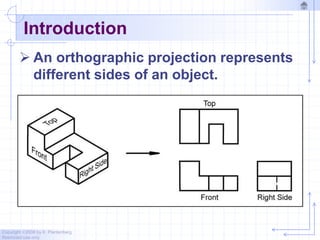
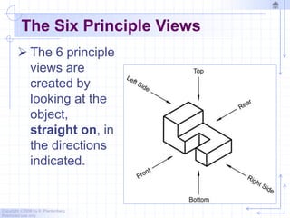
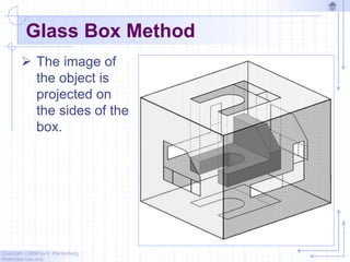
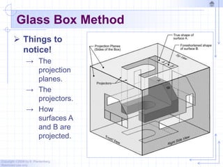
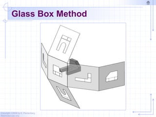
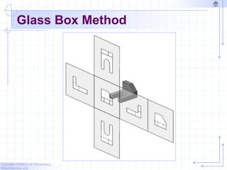
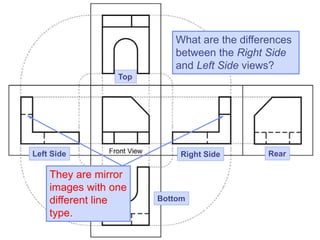
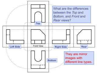
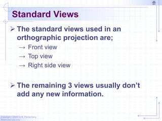
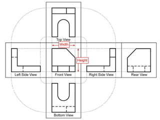
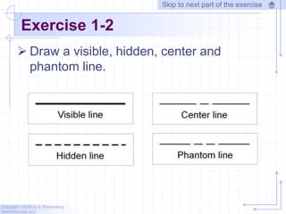
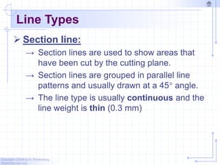
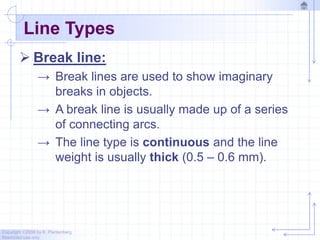
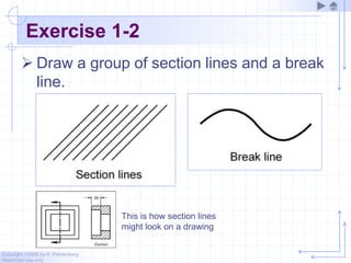
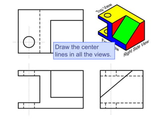
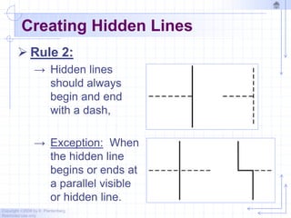
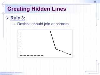
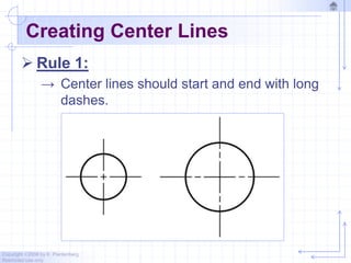
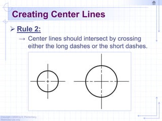
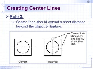
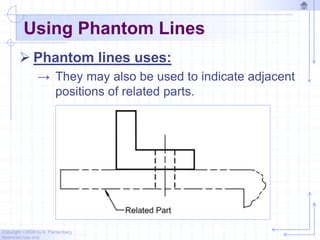
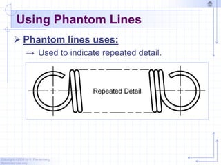
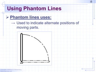
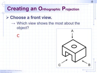
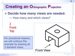
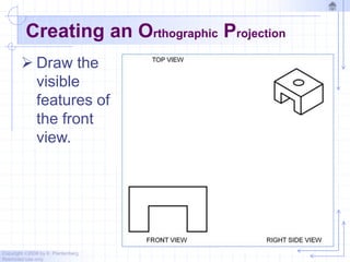
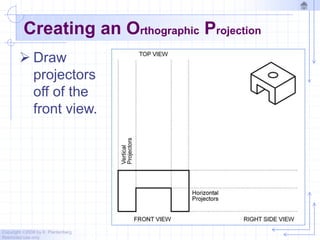
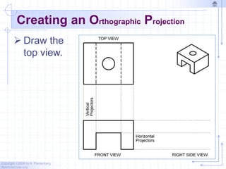
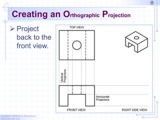
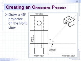
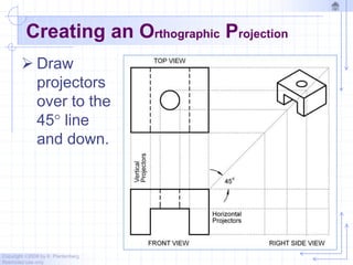
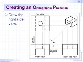
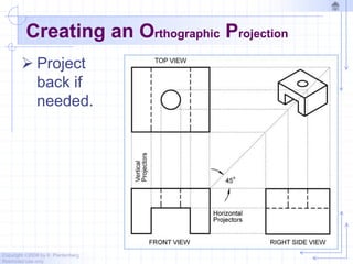
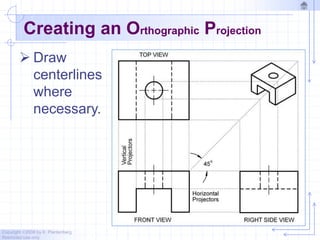
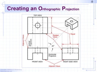
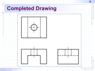
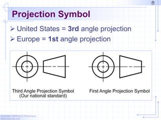
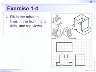
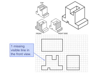
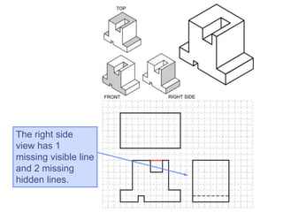
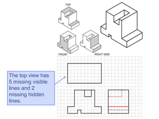
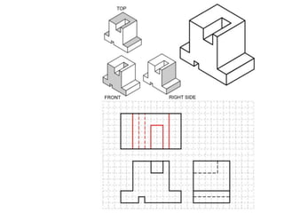
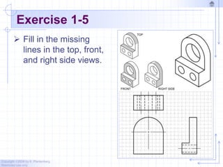
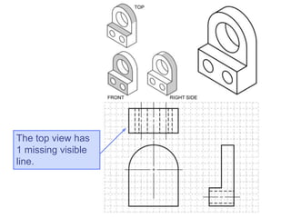
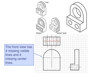
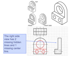
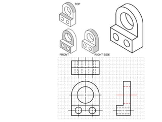
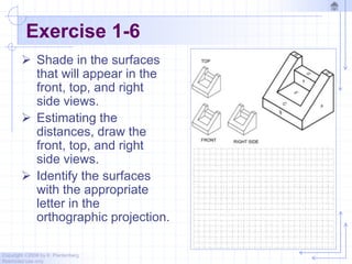
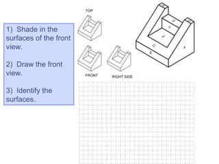
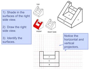
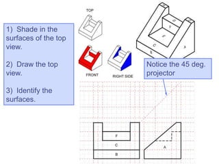
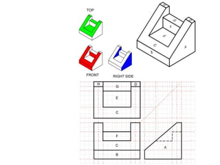
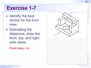
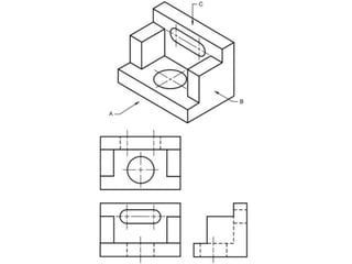
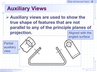
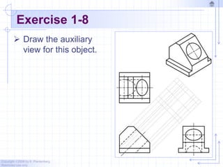
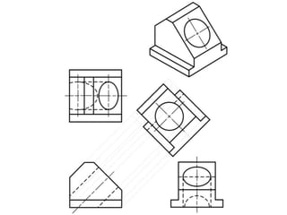
Copyright ©2006 by K. Plantenberg
Restricted use only
Orthographic Projection
1.2) Orthographic Projection
Introduction
Copyright ©2006 by K. Plantenberg
Restricted use only
Introduction
 An orthographic projection represents
different sides of an object.
Copyright ©2006 by K. Plantenberg
Restricted use only
The Six Principle Views
 The 6 principle
views are
created by
looking at the
object,
straight on, in
the directions
indicated.
Copyright ©2006 by K. Plantenberg
Restricted use only
Orthographic Projection
1.3) The Glass Box Method
Copyright ©2006 by K. Plantenberg
Restricted use only
The Glass Box Method
 How do we create the 6 principle
views?
→ Glass Box Method:
• The object is placed in a glass box.
• The image of the object is projected on the sides
of the box.
• The box is unfolded.
• The sides of the box are the principle views.
Copyright ©2006 by K. Plantenberg
Restricted use only
Glass Box Method
 The image of
the object is
projected on
the sides of the
box.
Copyright ©2006 by K. Plantenberg
Restricted use only
Glass Box Method
 Things to
notice!
→ The
projection
planes.
→ The
projectors.
→ How
surfaces A
and B are
projected.
Copyright ©2006 by K. Plantenberg
Restricted use only
Glass Box Method
Copyright ©2006 by K. Plantenberg
Restricted use only
Glass Box Method
What are the differences
between the Right Side
and Left Side views?
Top
Right Side Rear
Left Side
Bottom
They are mirror
images with one
different line
type.
What are the differences
between the Top and
Bottom, and Front and
Rear views?
Top
Right Side Rear
Left Side
Bottom
They are mirror
images with
different line types.
Copyright ©2006 by K. Plantenberg
Restricted use only
Standard Views
 The standard views used in an
orthographic projection are;
→ Front view
→ Top view
→ Right side view
 The remaining 3 views usually don’t
add any new information.
Copyright ©2006 by K. Plantenberg
Restricted use only
Front View
 The front view shows the most features
or characteristics of the object.
→ It usually contains the least amount of
hidden lines.
→ The front view is chosen first and the other
views are based on the orientation of the
front view.
Copyright ©2006 by K. Plantenberg
Restricted use only
View Alignment
 The top and front views are aligned
vertically and share the same width
dimension.
 The front and right side views are
aligned horizontally and share the same
height dimension.
Copyright ©2006 by K. Plantenberg
Restricted use only
Exercise 1-2
 Draw a visible, hidden, center and
phantom line.
Skip to next part of the exercise
Copyright ©2006 by K. Plantenberg
Restricted use only
Line Types
 More on Center lines:
→ Important for interpreting cylindrical shapes.
→ Crossed center lines should be drawn at the
centers of circles.
Copyright ©2006 by K. Plantenberg
Restricted use only
Line Types
 More on Center lines:
→ They are also used to indicate circle of
centers and paths of motion.
Copyright ©2006 by K. Plantenberg
Restricted use only
Line Types
 Cutting Plane line:
→ Cutting plane lines are used to show where
an imaginary cut has been made through
the object in order to view interior features.
→ The line type is phantom and the line
weight is very thick (0.6 to 0.8 mm).
→ Arrows are placed at both ends of the
cutting plane line to indicate the direction of
sight.
Copyright ©2006 by K. Plantenberg
Restricted use only
Exercise 1-2
 Draw a dimension/extension line and a
cutting plane line.
Skip to next part of the exercise
Copyright ©2006 by K. Plantenberg
Restricted use only
Line Types
 Section line:
→ Section lines are used to show areas that
have been cut by the cutting plane.
→ Section lines are grouped in parallel line
patterns and usually drawn at a 45 angle.
→ The line type is usually continuous and the
line weight is thin (0.3 mm)
Copyright ©2006 by K. Plantenberg
Restricted use only
Line Types
 Break line:
→ Break lines are used to show imaginary
breaks in objects.
→ A break line is usually made up of a series
of connecting arcs.
→ The line type is continuous and the line
weight is usually thick (0.5 – 0.6 mm).
Copyright ©2006 by K. Plantenberg
Restricted use only
Exercise 1-2
 Draw a group of section lines and a break
line.
This is how section lines
might look on a drawing
Draw the center
lines in all the views.
Copyright ©2006 by K. Plantenberg
Restricted use only
Creating Hidden Lines
 Rule 2:
→ Hidden lines
should always
begin and end
with a dash,
→ Exception: When
the hidden line
begins or ends at
a parallel visible
or hidden line.
Copyright ©2006 by K. Plantenberg
Restricted use only
Creating Hidden Lines
 Rule 3:
→ Dashes should join at corners.
Copyright ©2006 by K. Plantenberg
Restricted use only
Creating Center Lines
 Rule 1:
→ Center lines should start and end with long
dashes.
Copyright ©2006 by K. Plantenberg
Restricted use only
Creating Center Lines
 Rule 2:
→ Center lines should intersect by crossing
either the long dashes or the short dashes.
Copyright ©2006 by K. Plantenberg
Restricted use only
Creating Center Lines
 Rule 3:
→ Center lines should extend a short distance
beyond the object or feature.
Copyright ©2006 by K. Plantenberg
Restricted use only
Using Phantom Lines
 Phantom lines uses:
→ They may also be used to indicate adjacent
positions of related parts.
Copyright ©2006 by K. Plantenberg
Restricted use only
Using Phantom Lines
 Phantom lines uses:
→ Used to indicate repeated detail.
Copyright ©2006 by K. Plantenberg
Restricted use only
Using Phantom Lines
 Phantom lines uses:
→ Used to indicate alternate positions of
moving parts.
Copyright ©2006 by K. Plantenberg
Restricted use only
Using Break Lines
 Break lines are used to show imaginary
breaks in an object.
Copyright ©2006 by K. Plantenberg
Restricted use only
Creating Break Lines
 There are two types of break lines.
→ If the distance to traverse is short the series
of connecting arcs is used.
Copyright ©2006 by K. Plantenberg
Restricted use only
Creating Break Lines
 There are two types of break lines.
→ If the distance is long the thin straight line
with a jog is used.
Copyright ©2006 by K. Plantenberg
Restricted use only
Line Precedence
 If two lines occur in the same place, the
line that is considered to be the least
important is omitted.
 Lines in order of precedence/importance
are as follows;
→ Cutting plane line
→ Visible line
→ Hidden line
→ Centerline
Copyright ©2006 by K. Plantenberg
Restricted use only
Creating an Orthographic Projection
 Choose a front view.
→ Which view shows the most about the
object?
C
Copyright ©2006 by K. Plantenberg
Restricted use only
Creating an Orthographic Projection
 Decide how many views are needed.
→ How many and which views?
2
Front
Top
For procedural reasons,
we will continue this
example by drawing all
3 standard views.
Copyright ©2006 by K. Plantenberg
Restricted use only
Creating an Orthographic Projection
 Draw the
visible
features of
the front
view.
Copyright ©2006 by K. Plantenberg
Restricted use only
Creating an Orthographic Projection
 Draw
projectors
off of the
front view.
Copyright ©2006 by K. Plantenberg
Restricted use only
Creating an Orthographic Projection
 Draw the
top view.
Copyright ©2006 by K. Plantenberg
Restricted use only
Creating an Orthographic Projection
 Project
back to the
front view.
Copyright ©2006 by K. Plantenberg
Restricted use only
Creating an Orthographic Projection
 Draw a 45
projector
off the front
view.
Copyright ©2006 by K. Plantenberg
Restricted use only
Creating an Orthographic Projection
 Draw
projectors
over to the
45 line
and down.
Copyright ©2006 by K. Plantenberg
Restricted use only
Creating an Orthographic Projection
 Draw the
right side
view.
Copyright ©2006 by K. Plantenberg
Restricted use only
Creating an Orthographic Projection
 Project
back if
needed.
Copyright ©2006 by K. Plantenberg
Restricted use only
Creating an Orthographic Projection
 Draw
centerlines
where
necessary.
Copyright ©2006 by K. Plantenberg
Restricted use only
Creating an Orthographic Projection
Copyright ©2006 by K. Plantenberg
Restricted use only
Completed Drawing
Copyright ©2006 by K. Plantenberg
Restricted use only
Projection Symbol
 United States = 3rd angle projection
 Europe = 1st angle projection
Copyright ©2006 by K. Plantenberg
Restricted use only
Exercise 1-4
 Fill in the missing
lines in the front, right
side, and top views.
1 missing
visible line in
the front view.
The right side
view has 1
missing visible line
and 2 missing
hidden lines.
The top view has
5 missing visible
lines and 2
missing hidden
lines.
Copyright ©2006 by K. Plantenberg
Restricted use only
Exercise 1-5
 Fill in the missing
lines in the top, front,
and right side views.
The top view has
1 missing visible
line.
The front view has
4 missing visible
lines and 4
missing center
lines.
The right side
view has 2
missing hidden
lines and 1
missing center
line.
Copyright ©2006 by K. Plantenberg
Restricted use only
Exercise 1-6
 Shade in the surfaces
that will appear in the
front, top, and right
side views.
 Estimating the
distances, draw the
front, top, and right
side views.
 Identify the surfaces
with the appropriate
letter in the
orthographic projection.
1) Shade in the
surfaces of the front
view.
2) Draw the front
view.
3) Identify the
surfaces.
1) Shade in the
surfaces of the right
side view.
2) Draw the right
side view.
3) Identify the
surfaces.
Notice the
horizontal and
vertical
projectors.
1) Shade in the
surfaces of the top
view.
2) Draw the top
view.
3) Identify the
surfaces.
Notice the 45 deg.
projector
Copyright ©2006 by K. Plantenberg
Restricted use only
Exercise 1-7
 Identify the best
choice for the front
view.
 Estimating the
distances, draw the
front, top, and right
side views.
Front view = A
Copyright ©2006 by K. Plantenberg
Restricted use only
Auxiliary Views
 Auxiliary views are used to show the
true shape of features that are not
parallel to any of the principle planes of
projection. Aligned with the
angled surface
Partial
auxiliary
view
Skip advanced topic
Copyright ©2006 by K. Plantenberg
Restricted use only
Exercise 1-8
 Draw the auxiliary
view for this object.
W 1 chapter 1   orthographic projection

W 1 chapter 1 orthographic projection

  • 1.
    Copyright ©2006 byK. Plantenberg Restricted use only Orthographic Projection 1.2) Orthographic Projection Introduction
  • 2.
    Copyright ©2006 byK. Plantenberg Restricted use only Introduction  An orthographic projection represents different sides of an object.
  • 3.
    Copyright ©2006 byK. Plantenberg Restricted use only The Six Principle Views  The 6 principle views are created by looking at the object, straight on, in the directions indicated.
  • 4.
    Copyright ©2006 byK. Plantenberg Restricted use only Orthographic Projection 1.3) The Glass Box Method
  • 5.
    Copyright ©2006 byK. Plantenberg Restricted use only The Glass Box Method  How do we create the 6 principle views? → Glass Box Method: • The object is placed in a glass box. • The image of the object is projected on the sides of the box. • The box is unfolded. • The sides of the box are the principle views.
  • 6.
    Copyright ©2006 byK. Plantenberg Restricted use only Glass Box Method  The image of the object is projected on the sides of the box.
  • 7.
    Copyright ©2006 byK. Plantenberg Restricted use only Glass Box Method  Things to notice! → The projection planes. → The projectors. → How surfaces A and B are projected.
  • 8.
    Copyright ©2006 byK. Plantenberg Restricted use only Glass Box Method
  • 9.
    Copyright ©2006 byK. Plantenberg Restricted use only Glass Box Method
  • 10.
    What are thedifferences between the Right Side and Left Side views? Top Right Side Rear Left Side Bottom They are mirror images with one different line type.
  • 11.
    What are thedifferences between the Top and Bottom, and Front and Rear views? Top Right Side Rear Left Side Bottom They are mirror images with different line types.
  • 12.
    Copyright ©2006 byK. Plantenberg Restricted use only Standard Views  The standard views used in an orthographic projection are; → Front view → Top view → Right side view  The remaining 3 views usually don’t add any new information.
  • 13.
    Copyright ©2006 byK. Plantenberg Restricted use only Front View  The front view shows the most features or characteristics of the object. → It usually contains the least amount of hidden lines. → The front view is chosen first and the other views are based on the orientation of the front view.
  • 14.
    Copyright ©2006 byK. Plantenberg Restricted use only View Alignment  The top and front views are aligned vertically and share the same width dimension.  The front and right side views are aligned horizontally and share the same height dimension.
  • 16.
    Copyright ©2006 byK. Plantenberg Restricted use only Exercise 1-2  Draw a visible, hidden, center and phantom line. Skip to next part of the exercise
  • 17.
    Copyright ©2006 byK. Plantenberg Restricted use only Line Types  More on Center lines: → Important for interpreting cylindrical shapes. → Crossed center lines should be drawn at the centers of circles.
  • 18.
    Copyright ©2006 byK. Plantenberg Restricted use only Line Types  More on Center lines: → They are also used to indicate circle of centers and paths of motion.
  • 19.
    Copyright ©2006 byK. Plantenberg Restricted use only Line Types  Cutting Plane line: → Cutting plane lines are used to show where an imaginary cut has been made through the object in order to view interior features. → The line type is phantom and the line weight is very thick (0.6 to 0.8 mm). → Arrows are placed at both ends of the cutting plane line to indicate the direction of sight.
  • 20.
    Copyright ©2006 byK. Plantenberg Restricted use only Exercise 1-2  Draw a dimension/extension line and a cutting plane line. Skip to next part of the exercise
  • 21.
    Copyright ©2006 byK. Plantenberg Restricted use only Line Types  Section line: → Section lines are used to show areas that have been cut by the cutting plane. → Section lines are grouped in parallel line patterns and usually drawn at a 45 angle. → The line type is usually continuous and the line weight is thin (0.3 mm)
  • 22.
    Copyright ©2006 byK. Plantenberg Restricted use only Line Types  Break line: → Break lines are used to show imaginary breaks in objects. → A break line is usually made up of a series of connecting arcs. → The line type is continuous and the line weight is usually thick (0.5 – 0.6 mm).
  • 23.
    Copyright ©2006 byK. Plantenberg Restricted use only Exercise 1-2  Draw a group of section lines and a break line. This is how section lines might look on a drawing
  • 24.
    Draw the center linesin all the views.
  • 25.
    Copyright ©2006 byK. Plantenberg Restricted use only Creating Hidden Lines  Rule 2: → Hidden lines should always begin and end with a dash, → Exception: When the hidden line begins or ends at a parallel visible or hidden line.
  • 26.
    Copyright ©2006 byK. Plantenberg Restricted use only Creating Hidden Lines  Rule 3: → Dashes should join at corners.
  • 27.
    Copyright ©2006 byK. Plantenberg Restricted use only Creating Center Lines  Rule 1: → Center lines should start and end with long dashes.
  • 28.
    Copyright ©2006 byK. Plantenberg Restricted use only Creating Center Lines  Rule 2: → Center lines should intersect by crossing either the long dashes or the short dashes.
  • 29.
    Copyright ©2006 byK. Plantenberg Restricted use only Creating Center Lines  Rule 3: → Center lines should extend a short distance beyond the object or feature.
  • 30.
    Copyright ©2006 byK. Plantenberg Restricted use only Using Phantom Lines  Phantom lines uses: → They may also be used to indicate adjacent positions of related parts.
  • 31.
    Copyright ©2006 byK. Plantenberg Restricted use only Using Phantom Lines  Phantom lines uses: → Used to indicate repeated detail.
  • 32.
    Copyright ©2006 byK. Plantenberg Restricted use only Using Phantom Lines  Phantom lines uses: → Used to indicate alternate positions of moving parts.
  • 33.
    Copyright ©2006 byK. Plantenberg Restricted use only Using Break Lines  Break lines are used to show imaginary breaks in an object.
  • 34.
    Copyright ©2006 byK. Plantenberg Restricted use only Creating Break Lines  There are two types of break lines. → If the distance to traverse is short the series of connecting arcs is used.
  • 35.
    Copyright ©2006 byK. Plantenberg Restricted use only Creating Break Lines  There are two types of break lines. → If the distance is long the thin straight line with a jog is used.
  • 36.
    Copyright ©2006 byK. Plantenberg Restricted use only Line Precedence  If two lines occur in the same place, the line that is considered to be the least important is omitted.  Lines in order of precedence/importance are as follows; → Cutting plane line → Visible line → Hidden line → Centerline
  • 37.
    Copyright ©2006 byK. Plantenberg Restricted use only Creating an Orthographic Projection  Choose a front view. → Which view shows the most about the object? C
  • 38.
    Copyright ©2006 byK. Plantenberg Restricted use only Creating an Orthographic Projection  Decide how many views are needed. → How many and which views? 2 Front Top For procedural reasons, we will continue this example by drawing all 3 standard views.
  • 39.
    Copyright ©2006 byK. Plantenberg Restricted use only Creating an Orthographic Projection  Draw the visible features of the front view.
  • 40.
    Copyright ©2006 byK. Plantenberg Restricted use only Creating an Orthographic Projection  Draw projectors off of the front view.
  • 41.
    Copyright ©2006 byK. Plantenberg Restricted use only Creating an Orthographic Projection  Draw the top view.
  • 42.
    Copyright ©2006 byK. Plantenberg Restricted use only Creating an Orthographic Projection  Project back to the front view.
  • 43.
    Copyright ©2006 byK. Plantenberg Restricted use only Creating an Orthographic Projection  Draw a 45 projector off the front view.
  • 44.
    Copyright ©2006 byK. Plantenberg Restricted use only Creating an Orthographic Projection  Draw projectors over to the 45 line and down.
  • 45.
    Copyright ©2006 byK. Plantenberg Restricted use only Creating an Orthographic Projection  Draw the right side view.
  • 46.
    Copyright ©2006 byK. Plantenberg Restricted use only Creating an Orthographic Projection  Project back if needed.
  • 47.
    Copyright ©2006 byK. Plantenberg Restricted use only Creating an Orthographic Projection  Draw centerlines where necessary.
  • 48.
    Copyright ©2006 byK. Plantenberg Restricted use only Creating an Orthographic Projection
  • 49.
    Copyright ©2006 byK. Plantenberg Restricted use only Completed Drawing
  • 50.
    Copyright ©2006 byK. Plantenberg Restricted use only Projection Symbol  United States = 3rd angle projection  Europe = 1st angle projection
  • 51.
    Copyright ©2006 byK. Plantenberg Restricted use only Exercise 1-4  Fill in the missing lines in the front, right side, and top views.
  • 52.
    1 missing visible linein the front view.
  • 53.
    The right side viewhas 1 missing visible line and 2 missing hidden lines.
  • 54.
    The top viewhas 5 missing visible lines and 2 missing hidden lines.
  • 56.
    Copyright ©2006 byK. Plantenberg Restricted use only Exercise 1-5  Fill in the missing lines in the top, front, and right side views.
  • 57.
    The top viewhas 1 missing visible line.
  • 58.
    The front viewhas 4 missing visible lines and 4 missing center lines.
  • 59.
    The right side viewhas 2 missing hidden lines and 1 missing center line.
  • 61.
    Copyright ©2006 byK. Plantenberg Restricted use only Exercise 1-6  Shade in the surfaces that will appear in the front, top, and right side views.  Estimating the distances, draw the front, top, and right side views.  Identify the surfaces with the appropriate letter in the orthographic projection.
  • 62.
    1) Shade inthe surfaces of the front view. 2) Draw the front view. 3) Identify the surfaces.
  • 63.
    1) Shade inthe surfaces of the right side view. 2) Draw the right side view. 3) Identify the surfaces. Notice the horizontal and vertical projectors.
  • 64.
    1) Shade inthe surfaces of the top view. 2) Draw the top view. 3) Identify the surfaces. Notice the 45 deg. projector
  • 66.
    Copyright ©2006 byK. Plantenberg Restricted use only Exercise 1-7  Identify the best choice for the front view.  Estimating the distances, draw the front, top, and right side views. Front view = A
  • 68.
    Copyright ©2006 byK. Plantenberg Restricted use only Auxiliary Views  Auxiliary views are used to show the true shape of features that are not parallel to any of the principle planes of projection. Aligned with the angled surface Partial auxiliary view Skip advanced topic
  • 69.
    Copyright ©2006 byK. Plantenberg Restricted use only Exercise 1-8  Draw the auxiliary view for this object.