Downloaded 171 times


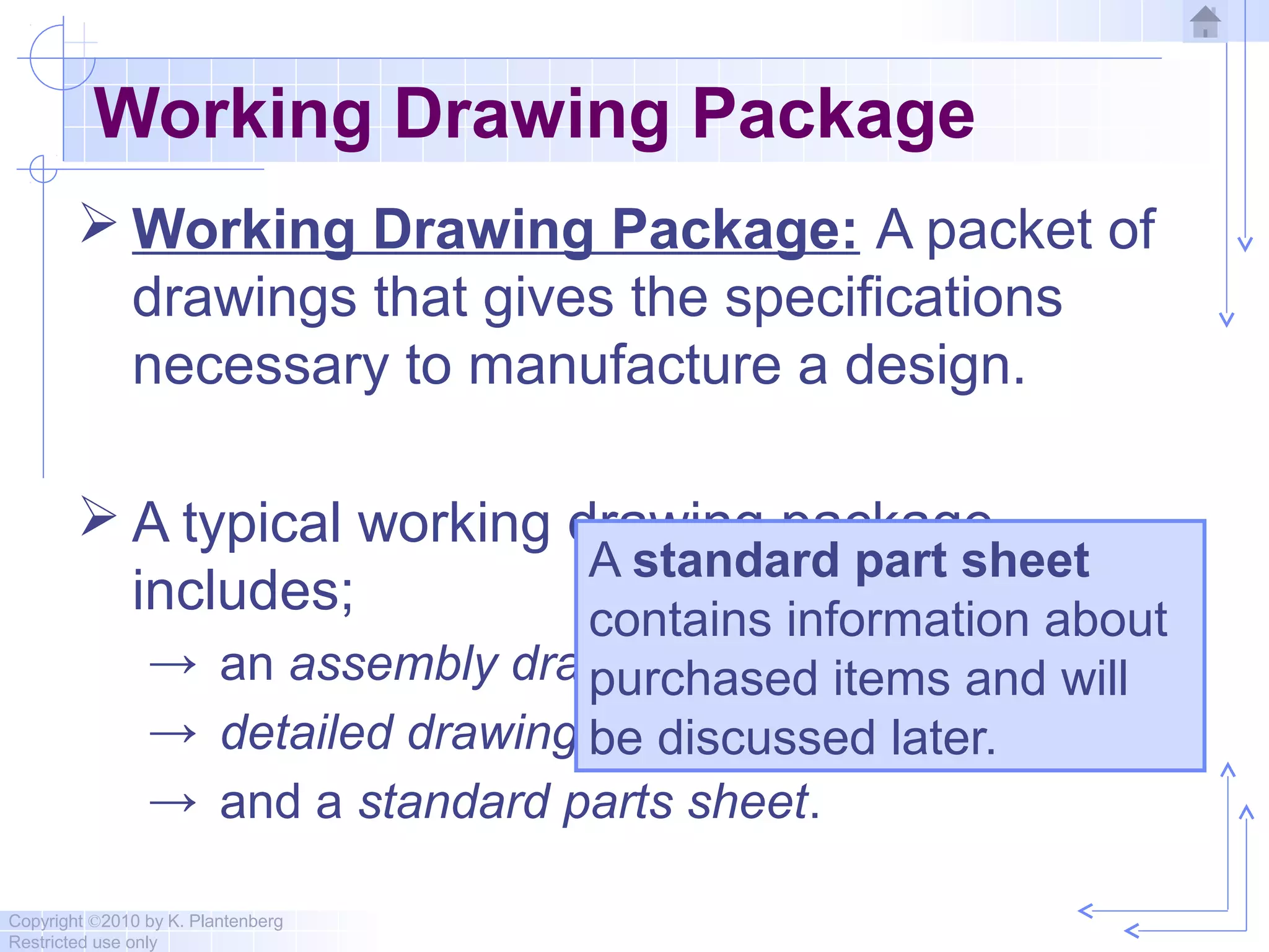
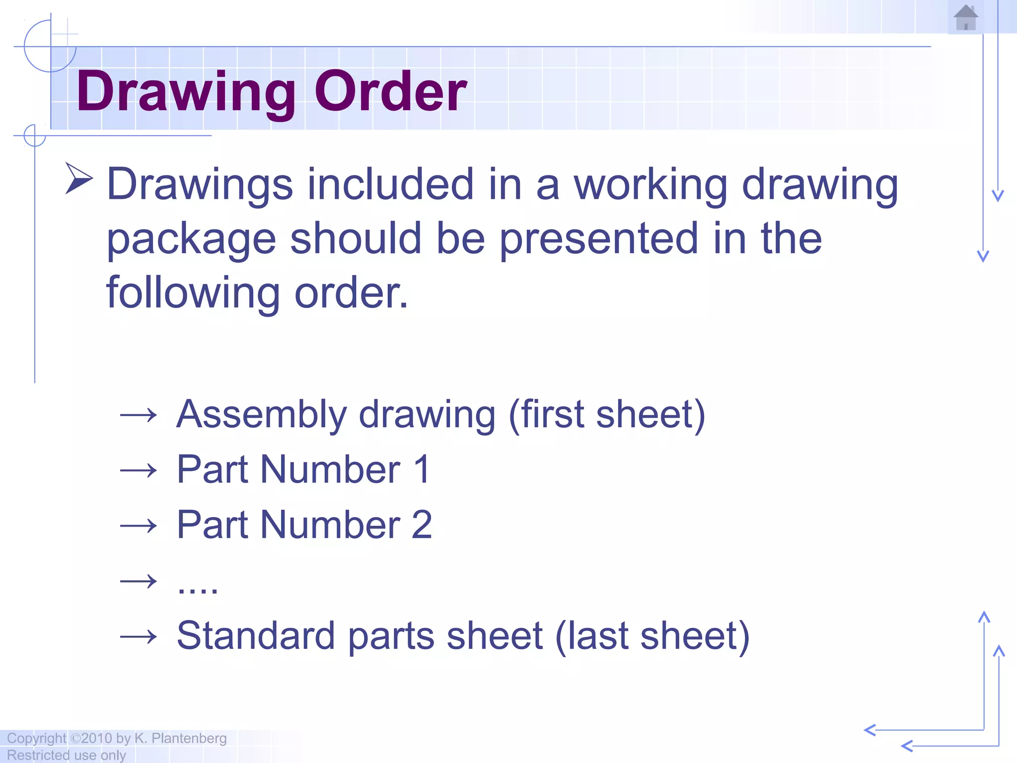


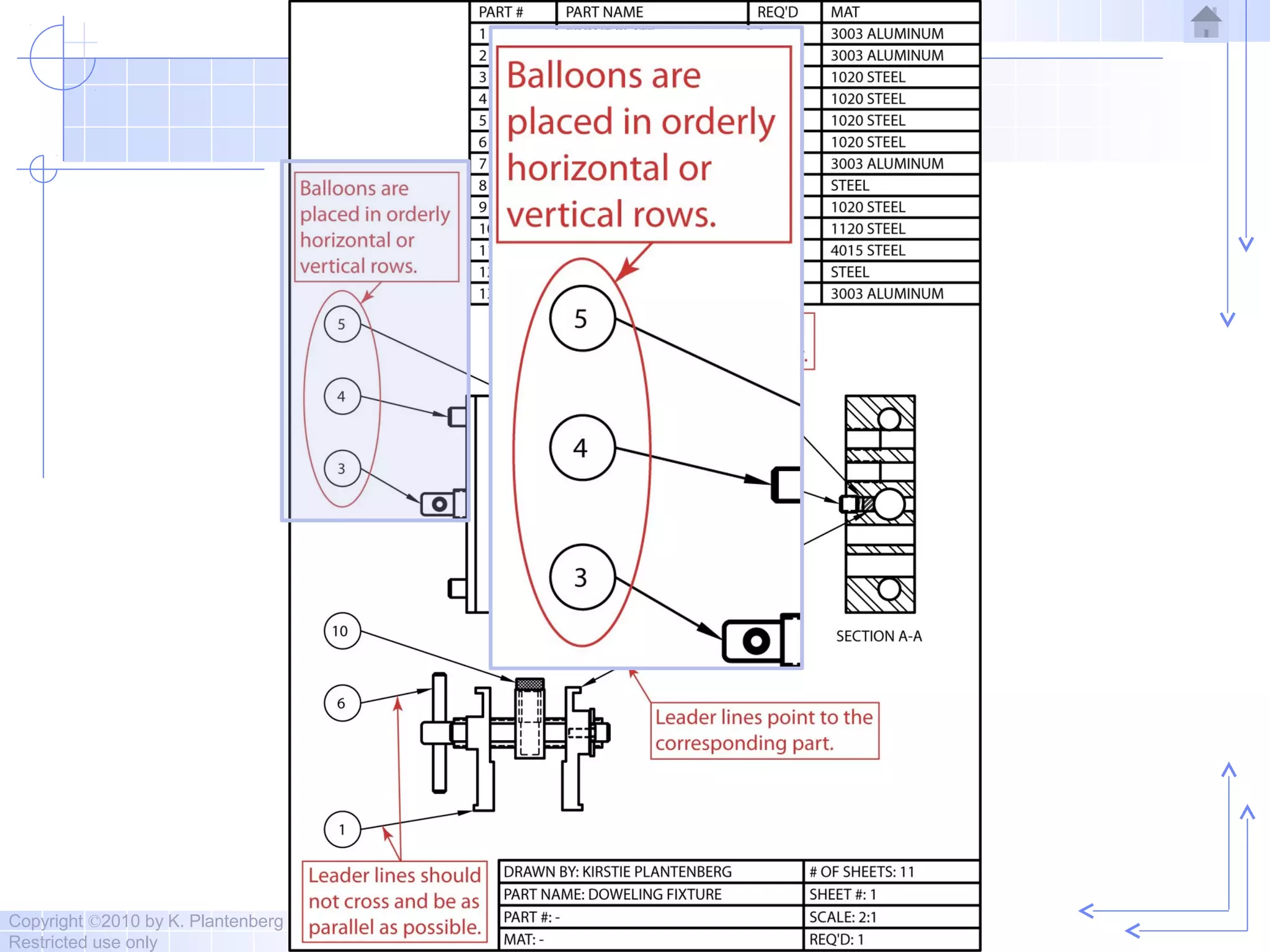


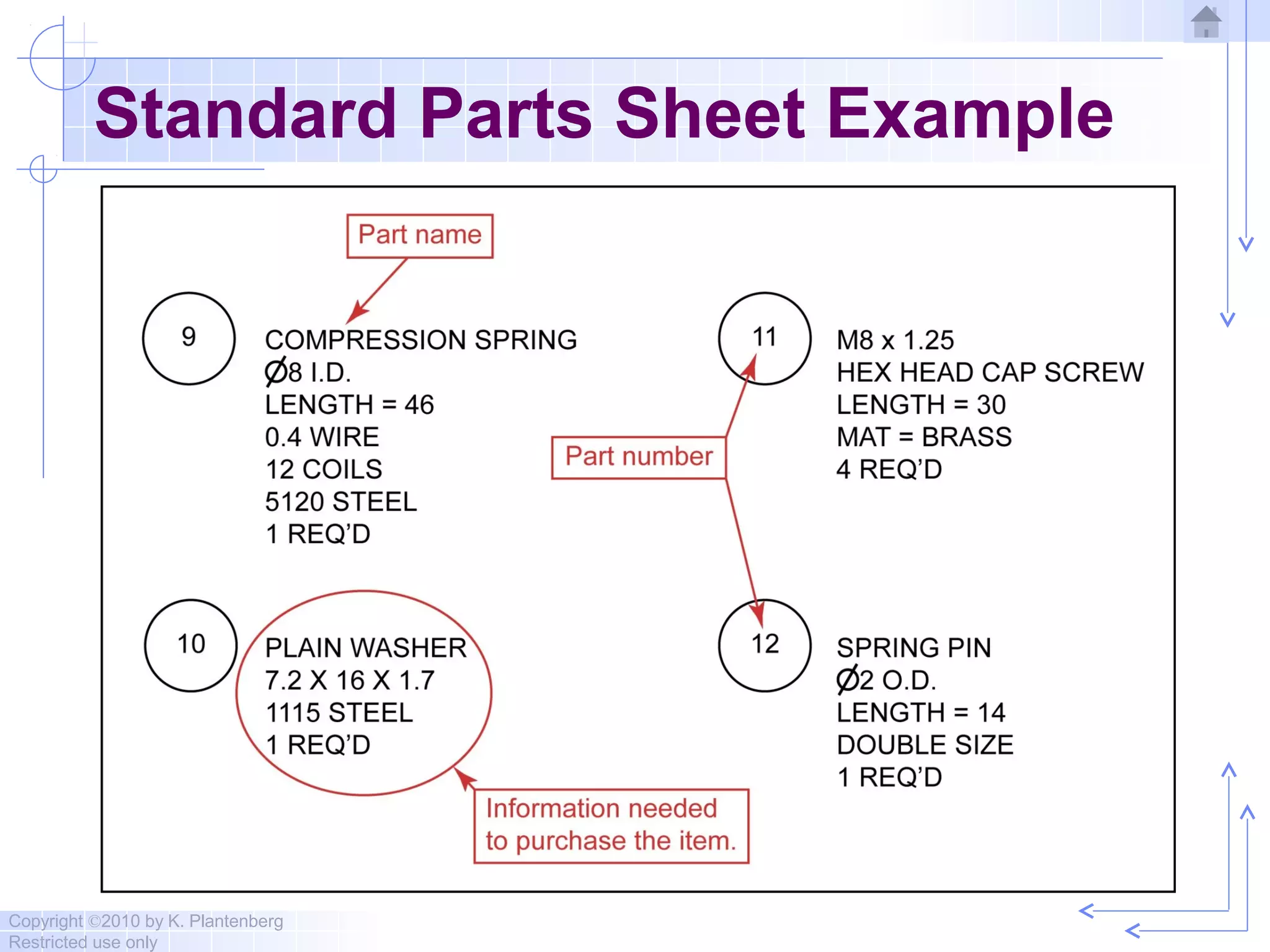


The document discusses assembly drawings and their components. It covers topics like: - The purpose of assembly drawings is to show how individual parts fit together to form a whole machine. - Views used may include full, cut-away, and exploded views to show hidden details. - Information included are ballooned part numbers and leaders pointing to parts, along with a corresponding parts list. Dimensions are usually omitted. - Standard parts that can be purchased off-the-shelf are specified on a separate standard parts sheet instead of being drawn. - Two exercises demonstrate creating an assembly drawing, detailed part drawings, and standard parts sheet for a sample clamp assembly.