Downloaded 187 times

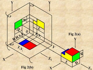


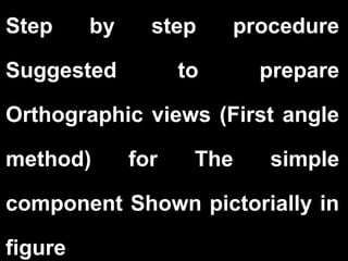


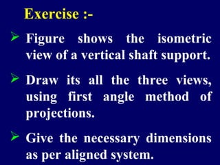


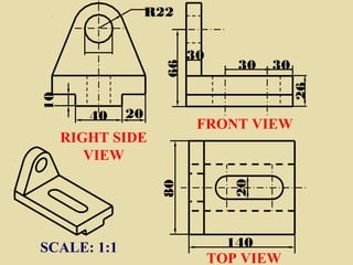


This document discusses orthographic projection and provides examples of drawing orthographic views from isometric views using first and third angle projection methods. It includes an isometric view of an object with its corresponding front, top, and right side orthographic views drawn to scale with dimensions. The document also provides step-by-step instructions for drawing orthographic projections of additional example objects from their isometric views using different projection methods.


![Ortographicprojection(thedirectdata[1].com)](https://cdn.slidesharecdn.com/ss_thumbnails/ortographicprojectionthedirectdata1-170802182401-thumbnail.jpg?width=640&height=640&fit=bounds)