Downloaded 282 times
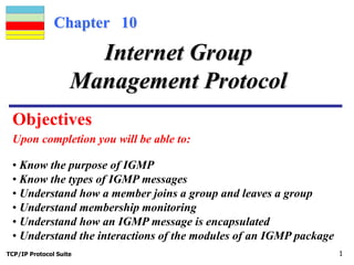


IGMP (Internet Group Management Protocol) allows multicast routers to track group memberships across multicast networks. It has three message types - query, membership report, and leave report. Upon receiving a query, hosts send membership reports to the router to join or leave groups. The router uses these reports to maintain a list of members for each multicast group on that network segment. IGMP messages are encapsulated in IP datagrams and Ethernet frames for transmission.