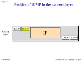
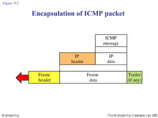
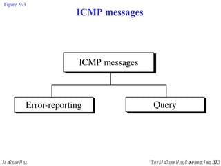
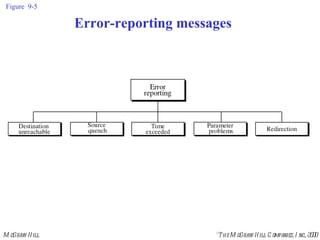
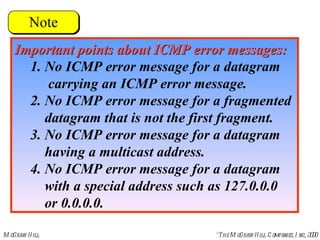
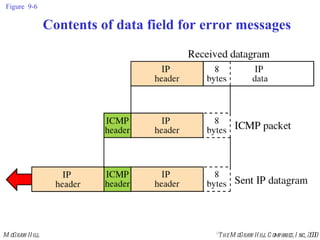
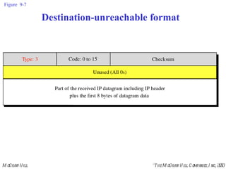
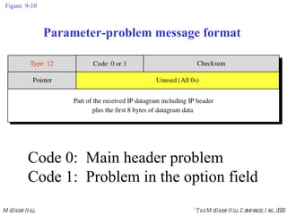
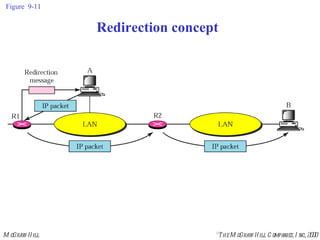
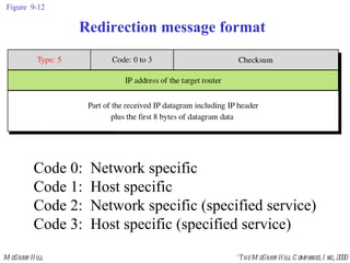
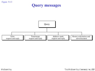
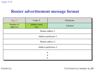
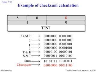
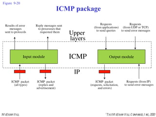
Chapter 9 Internet Control Message Protocol (ICMP)
CONTENTS TYPES OF MESSAGES MESSAGE FORMAT ERROR REPORTING QUERY CHECKSUM ICMP PACKAGE
Figure  9-1 Position of ICMP in the network layer
Figure  9-2 Encapsulation of ICMP packet
TYPES  OF  MESSAGES 9.1
Figure  9-3 ICMP messages
MESSAGE  FORMAT 9.2
Figure  9-4 General format of ICMP messages
ERROR REPORTING 9.3
ICMP always reports  error messages  to the original source.
Figure  9-5 Error-reporting messages
Important points about ICMP error messages: 1.   No ICMP error message for a datagram    carrying an ICMP error message. 2. No ICMP error message for a fragmented    datagram that is not the first fragment. 3. No ICMP error message for a datagram    having a multicast address. 4. No ICMP error message for a datagram    with a special address such as 127.0.0.0    or 0.0.0.0.
Figure  9-6 Contents of data field for error messages
Figure  9-7 Destination-unreachable format
Destination-unreachable messages with  codes 2 or 3 can be created only  by the destination host.  Other destination-unreachable  messages can  be created only by routers.
A router cannot detect all  problems that prevent  the delivery of a packet.
There is no flow-control mechanism  in the IP protocol.
Figure  9-8 Source-quench format
A source-quench message informs  the source that a datagram has been  discarded due to congestion  in a router or the destination host. The source must slow down the sending  of datagrams until the congestion  is relieved.
One source-quench message should  be sent for each  datagram that is discarded due  to congestion.
Whenever a router receives a datagram  with a time-to-live value of zero,  it discards the datagram and  sends a time-exceeded message to the original source.
When the final destination does not receive  all of the fragments in a set time,  it discards the received  fragments and sends  a time-exceeded message  to the original source.
In a time-exceeded message,  code 0 is used only by routers  to show that the value of  the time-to-live field is zero.  Code 1 is used only by the destination  host to show that not all of the  fragments have arrived within a set time.
Figure  9-9 Time-exceeded message format Code 0:  Time to live Code 1:  Fragmentation
A parameter-problem message can  be created by  a router or the destination host.
Figure  9-10 Parameter-problem message format Code 0:  Main header problem Code 1:  Problem in the option field
Figure  9-11 Redirection concept
A host usually starts with a small  routing table that is gradually  augmented and updated.  One of the tools to accomplish  this is the redirection message.
Figure  9-12 Redirection message format Code 0:  Network specific Code 1:  Host specific Code 2:  Network specific (specified service) Code 3:  Host specific (specified service)
A redirection message is  sent from a router to  a host on the same local network.
QUERY 9.4
Figure  9-13 Query messages
An echo-request message can be  sent by a host or router.  An echo-reply message is sent by the  host or router which receives  an echo-request message.
Echo-request and echo-reply messages  can be used by network managers to check the operation of the IP protocol.
Echo-request and echo-reply messages  can test the  reachability of a host.  This is usually done by  invoking the  ping  command.
Figure  9-14 Echo-request and echo-reply message format Ping command can use  theses messages.
Figure  9-15 Timestamp-request and  timestamp-reply message format
Sending time    value of receive timestamp     value of original timestamp Receiving time    time the packet returned     value of transmit timestamp Round-trip time    sending time     receiving time
Timestamp-request and  timestamp-reply messages can be used to  calculate the round-trip time  between a source and a destination  machine even if their  clocks are not synchronized.
Value of original timestamp: 46 Value of receive timestamp: 59 Value of transmit timestamp: 60 Time the packet arrived: 67 Given the following information:
Sending time    59    46   13 milliseconds Receiving time    67    60    7 milliseconds Round-trip time    13    7   20 milliseconds  We can calculate:
Time difference    receive timestamp     (original timestamp field      one-way time duration) Given the actual one-way time,
Time difference    59    (46    10)    3 We have:
The timestamp-request and  timestamp-reply messages  can be used to synchronize two  clocks in two machines if the  exact one-way time duration is known.
Figure  9-16 Mask-request and mask-reply message format
Figure  9-17 Router solicitation message format
Figure  9-18 Router advertisement message format
CHECKSUM 9.5
Figure  9-19 Example of checksum calculation
ICMP PACKAGE 9.6
Figure  9-20 ICMP package

Ch09

  • 1.
    Chapter 9 InternetControl Message Protocol (ICMP)
  • 2.
    CONTENTS TYPES OFMESSAGES MESSAGE FORMAT ERROR REPORTING QUERY CHECKSUM ICMP PACKAGE
  • 3.
    Figure 9-1Position of ICMP in the network layer
  • 4.
    Figure 9-2Encapsulation of ICMP packet
  • 5.
    TYPES OF MESSAGES 9.1
  • 6.
    Figure 9-3ICMP messages
  • 7.
  • 8.
    Figure 9-4General format of ICMP messages
  • 9.
  • 10.
    ICMP always reports error messages to the original source.
  • 11.
    Figure 9-5Error-reporting messages
  • 12.
    Important points aboutICMP error messages: 1. No ICMP error message for a datagram carrying an ICMP error message. 2. No ICMP error message for a fragmented datagram that is not the first fragment. 3. No ICMP error message for a datagram having a multicast address. 4. No ICMP error message for a datagram with a special address such as 127.0.0.0 or 0.0.0.0.
  • 13.
    Figure 9-6Contents of data field for error messages
  • 14.
    Figure 9-7Destination-unreachable format
  • 15.
    Destination-unreachable messages with codes 2 or 3 can be created only by the destination host. Other destination-unreachable messages can be created only by routers.
  • 16.
    A router cannotdetect all problems that prevent the delivery of a packet.
  • 17.
    There is noflow-control mechanism in the IP protocol.
  • 18.
    Figure 9-8Source-quench format
  • 19.
    A source-quench messageinforms the source that a datagram has been discarded due to congestion in a router or the destination host. The source must slow down the sending of datagrams until the congestion is relieved.
  • 20.
    One source-quench messageshould be sent for each datagram that is discarded due to congestion.
  • 21.
    Whenever a routerreceives a datagram with a time-to-live value of zero, it discards the datagram and sends a time-exceeded message to the original source.
  • 22.
    When the finaldestination does not receive all of the fragments in a set time, it discards the received fragments and sends a time-exceeded message to the original source.
  • 23.
    In a time-exceededmessage, code 0 is used only by routers to show that the value of the time-to-live field is zero. Code 1 is used only by the destination host to show that not all of the fragments have arrived within a set time.
  • 24.
    Figure 9-9Time-exceeded message format Code 0: Time to live Code 1: Fragmentation
  • 25.
    A parameter-problem messagecan be created by a router or the destination host.
  • 26.
    Figure 9-10Parameter-problem message format Code 0: Main header problem Code 1: Problem in the option field
  • 27.
    Figure 9-11Redirection concept
  • 28.
    A host usuallystarts with a small routing table that is gradually augmented and updated. One of the tools to accomplish this is the redirection message.
  • 29.
    Figure 9-12Redirection message format Code 0: Network specific Code 1: Host specific Code 2: Network specific (specified service) Code 3: Host specific (specified service)
  • 30.
    A redirection messageis sent from a router to a host on the same local network.
  • 31.
  • 32.
    Figure 9-13Query messages
  • 33.
    An echo-request messagecan be sent by a host or router. An echo-reply message is sent by the host or router which receives an echo-request message.
  • 34.
    Echo-request and echo-replymessages can be used by network managers to check the operation of the IP protocol.
  • 35.
    Echo-request and echo-replymessages can test the reachability of a host. This is usually done by invoking the ping command.
  • 36.
    Figure 9-14Echo-request and echo-reply message format Ping command can use theses messages.
  • 37.
    Figure 9-15Timestamp-request and timestamp-reply message format
  • 38.
    Sending time  value of receive timestamp  value of original timestamp Receiving time  time the packet returned  value of transmit timestamp Round-trip time  sending time  receiving time
  • 39.
    Timestamp-request and timestamp-reply messages can be used to calculate the round-trip time between a source and a destination machine even if their clocks are not synchronized.
  • 40.
    Value of originaltimestamp: 46 Value of receive timestamp: 59 Value of transmit timestamp: 60 Time the packet arrived: 67 Given the following information:
  • 41.
    Sending time  59  46  13 milliseconds Receiving time  67  60  7 milliseconds Round-trip time  13  7  20 milliseconds We can calculate:
  • 42.
    Time difference  receive timestamp  (original timestamp field  one-way time duration) Given the actual one-way time,
  • 43.
    Time difference  59  (46  10)  3 We have:
  • 44.
    The timestamp-request and timestamp-reply messages can be used to synchronize two clocks in two machines if the exact one-way time duration is known.
  • 45.
    Figure 9-16Mask-request and mask-reply message format
  • 46.
    Figure 9-17Router solicitation message format
  • 47.
    Figure 9-18Router advertisement message format
  • 48.
  • 49.
    Figure 9-19Example of checksum calculation
  • 50.
  • 51.
    Figure 9-20ICMP package