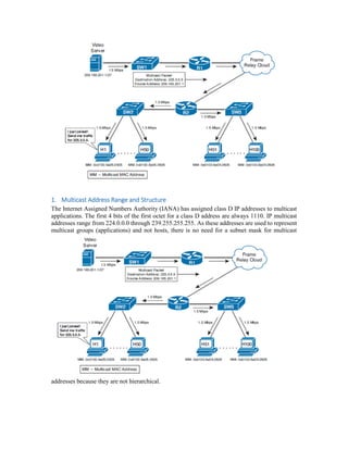
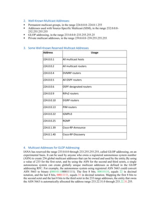
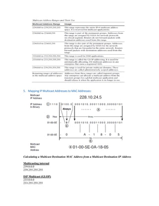
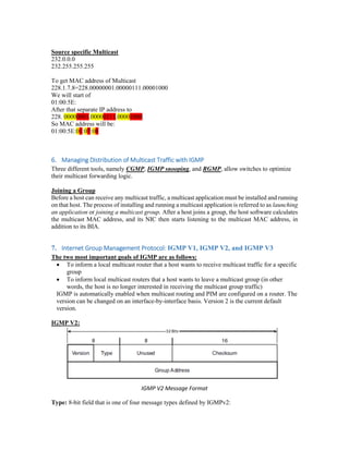
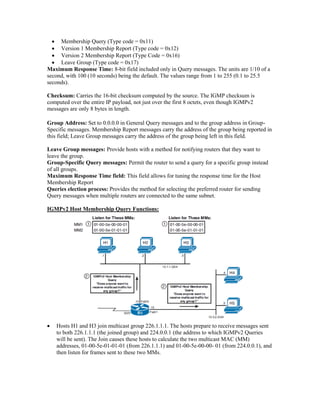
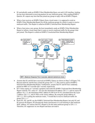
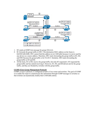
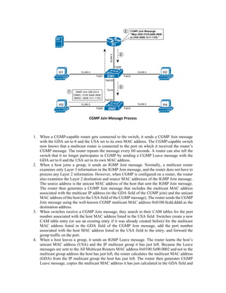
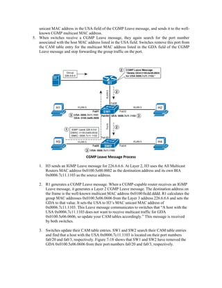
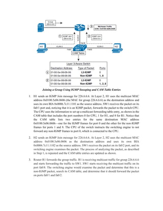
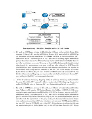
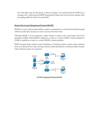
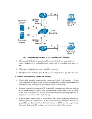
Multicast IP Addresses
Contents
1. Multicast Address Range and Structure.................................................................................. 3
2. Well-Known Multicast Addresses:........................................................................................... 4
3. Some Well-Known Reserved Multicast Addresses.................................................................. 4
4. Multicast Addresses for GLOP Addressing:............................................................................. 4
5. Mapping IP Multicast Addresses to MAC Addresses:.............................................................. 5
6. Managing Distribution of Multicast Traffic with IGMP ........................................................... 6
7. Internet Group Management Protocol: IGMP V1, IGMP V2, and IGMP V3 ....................... 6
8. LAN Multicast Optimizations................................................................................................. 12
9. IGMP Snooping...................................................................................................................... 16
1. Multicast Address Range and Structure
The Internet Assigned Numbers Authority (IANA) has assigned class D IP addresses to multicast
applications. The first 4 bits of the first octet for a class D address are always 1110. IP multicast
addresses range from 224.0.0.0 through 239.255.255.255. As these addresses are used to represent
multicast groups (applications) and not hosts, there is no need for a subnet mask for multicast
addresses because they are not hierarchical.
2. Well-Known Multicast Addresses:
 Permanent multicast groups, in the range 224.0.0.0–224.0.1.255
 Addresses used with Source-Specific Multicast (SSM), in the range 232.0.0.0–
232.255.255.255
 GLOP addressing, in the range 233.0.0.0–233.255.255.25
 Private multicast addresses, in the range 239.0.0.0–239.255.255.255
3. Some Well-Known Reserved Multicast Addresses
Address Usage
224.0.0.1 All multicast hosts
224.0.0.2 All multicast routers
224.0.0.4 DVMRP routers
224.0.0.5 All OSPF routers
224.0.0.6 OSPF designated routers
224.0.0.9 RIPv2 routers
224.0.0.10 EIGRP routers
224.0.0.13 PIM routers
224.0.0.22 IGMPv3
224.0.0.25 RGMP
224.0.1.39 Cisco-RP-Announce
224.0.1.40 Cisco-RP-Discovery
4. Multicast Addresses for GLOP Addressing:
IANA has reserved the range 233.0.0.0 through 233.255.255.255, called GLOP addressing, on an
experimental basis. It can be used by anyone who owns a registered autonomous system number
(ASN) to create 256 global multicast addresses that can be owned and used by the entity.By using
a value of 233 for the first octet, and by using the ASN for the second and third octets, a single
autonomous system can create globally unique multicast addresses as defined in the GLOP
addressing RFC. For example, the autonomous system using registered ASN 5663 could convert
ASN 5663 to binary (0001011000011111). The first 8 bits, 00010110, equals 22 in decimal
notation, and the last 8 bits, 00011111, equals 31 in decimal notation. Mapping the first 8 bits to
the second octet and the last 8 bits to the third octet in the 233 range addresses, the entity that owns
the ASN 5663 is automatically allocated the address range 233.22.31.0 through 233.22.31.255.
5. Mapping IP Multicast Addresses to MAC Addresses:
Calculating a Multicast Destination MAC Address from a Multicast Destination IP Address
Multicasting internal
239.0.0.0
239.255.255.255
ISP Multicast (GLOP)
233.0.0.0
233.255.255.255
Source specific Multicast
232.0.0.0
232.255.255.255
To get MAC address of Multicast
228.1.7.8=228.00000001.00000111.00001000
We will start of
01:00:5E:
After that separate IP address to
228. 00000001.00000111.00001000
So MAC address will be:
01:00:5E:01:07:08
6. Managing Distribution of Multicast Traffic with IGMP
Three different tools, namely CGMP, IGMP snooping, and RGMP, allow switches to optimize
their multicast forwarding logic.
Joining a Group
Before a host can receive any multicast traffic, a multicast application must be installed and running
on that host. The process of installing and running a multicast application is referred to as launching
an application or joining a multicast group. After a host joins a group, the host software calculates
the multicast MAC address, and its NIC then starts listening to the multicast MAC address, in
addition to its BIA.
7. Internet Group Management Protocol: IGMP V1, IGMP V2, and IGMP V3
The two most important goals of IGMP are as follows:
 To inform a local multicast router that a host wants to receive multicast traffic for a specific
group
 To inform local multicast routers that a host wants to leave a multicast group (in other
words, the host is no longer interested in receiving the multicast group traffic)
IGMP is automatically enabled when multicast routing and PIM are configured on a router. The
version can be changed on an interface-by-interface basis. Version 2 is the current default
version.
IGMP V2:
IGMP V2 Message Format
Type: 8-bit field that is one of four message types defined by IGMPv2:
 Membership Query (Type code = 0x11)
 Version 1 Membership Report (Type code = 0x12)
 Version 2 Membership Report (Type Code = 0x16)
 Leave Group (Type code = 0x17)
Maximum Response Time: 8-bit field included only in Query messages. The units are 1/10 of a
second, with 100 (10 seconds) being the default. The values range from 1 to 255 (0.1 to 25.5
seconds).
Checksum: Carries the 16-bit checksum computed by the source. The IGMP checksum is
computed over the entire IP payload, not just over the first 8 octets, even though IGMPv2
messages are only 8 bytes in length.
Group Address: Set to 0.0.0.0 in General Query messages and to the group address in Group-
Specific messages. Membership Report messages carry the address of the group being reported in
this field; Leave Group messages carry the address of the group being left in this field.
Leave Group messages: Provide hosts with a method for notifying routers that they want to
leave the group.
Group-Specific Query messages: Permit the router to send a query for a specific group instead
of all groups.
Maximum Response Time field: This field allows for tuning the response time for the Host
Membership Report
Queries election process: Provides the method for selecting the preferred router for sending
Query messages when multiple routers are connected to the same subnet.
IGMPv2 Host Membership Query Functions:
 Hosts H1 and H3 join multicast group 226.1.1.1. The hosts prepare to receive messages sent
to both 226.1.1.1 (the joined group) and 224.0.0.1 (the address to which IGMPv2 Queries
will be sent). The Join causes these hosts to calculate the two multicast MAC (MM)
addresses, 01-00-5e-01-01-01 (from 226.1.1.1) and 01-00-5e-00-00- 01 (from 224.0.0.1), and
then listen for frames sent to these two MMs.
 R1 periodically sends an IGMPv2 Host Membership Query out each LAN interface, looking
for any host interested in receiving packets for any multicast group. After sending IGMPv2
Queries, R1 expects any host that has joined any group to reply with an IGMPv2 Report.
 When a host receives an IGMPv2 Query from a local router, it is supposed to send an
IGMPv2 Host Membership Report for all the multicast groups for which it wants to receive
multicast traffic. This Report is called an IGMPv2 Solicited Host Membership Report.
 When a host joins a new group, the host immediately sends an IGMPv2 Host Membership
Report to inform a local router that it wants to receive multicast traffic for the group it has
just joined. This Report is called an IGMPv2 Unsolicited Host Membership Report
 Assume that H1 and H3 have received an IGMPv2 Query (as shown in Step 2 of Figure 7-8).
Because both H1 and H3 have joined the group 226.1.1.1, they need to send an IGMPv2
Solicited Host Membership Report. Furthermore, assume that H1 and H3 have randomly
picked an MRT of 3 seconds and 1 second, respectively.
 H3’s timer expires in 1 second; it prepares and sends the IGMPv2 Solicited Host Membership
Report with the TTL value of 1. H3 uses the destination IP address 226.1.1.1 and its source IP
address 10.1.1.3, the destination MAC address 01-00-5e-01-01-01 calculated from the Layer
3 address 226.1.1.1, and it's BIA as the source address. By using the group address of
226.1.1.1, H3 is telling the multicast router, “I would like to receive multicast traffic for
group 226.1.1.1.”
 Hosts H1, H2, and R1 see the IGMPv2 Solicited Host Membership Report, but only H1 and
R1 process the Report. H2 discards the frame sent because it is not listening to that multicast
MAC address. H1 realizes that H3’s Report is for the same multicast group as 226.1.1.1.
Therefore, H1 suppresses its own Report and does not send it.
R1 Forwarding Traffic for Group 226.1.1.1 on Its Fa0/0 Interface
IGMPv2 Unsolicited Host Membership Report:
In IGMPv2, a host does not have to wait for a Host Membership Query message from the router.
Hosts can send an IGMPv2 Unsolicited Host Membership Report anytime a user launches a
multicast application. This feature reduces the waiting time for a host to receive traffic for a
multicast group.
H4 Sends IGMPv2 Unsolicited Host Membership Report
IGMPv2 Leave Group and Group-Specific Query Messages
In IGMPv2, when a host leaves a group, it sends an IGMPv2 Leave message. When an IGMPv2
router receives a
Leave message, it immediately sends a Group-Specific Query for that group. The Group- Specific
Query asks only whether any remaining hosts still want to receive packets for that single
multicast group. As a result, the router quickly knows whether to continue to forward traffic for
that multicast group.
The main advantage of IGMPv2 over IGMPv1 is IGMPv2’s shorter leave latency. An IGMPv1
router takes, by default, 3 minutes to conclude that the last host on the subnet has left a group and
no host on the subnet wants to receive traffic for the group.
How Group-Specific Queries Work with the IGMPv2 Leave Process
1. H1 sends an IGMPv2 Leave Group message. The destination address is 224.0.0.2, the well-
known address for All Multicast Routers to inform all routers on the subnet that “I don’t want
to receive multicast traffic for 226.1.1.1 anymore.”
2. R1 sends a Group-Specific Query. Routers do not keep track of hosts that are members of the
group, only the group memberships that are active. Because H1 has decided to leave
226.1.1.1, R1 needs to make sure that no other hosts off this interface still need to receive
packets for group 226.1.1.1. Therefore, R1 sends a Group- Specific Query using 226.1.1.1 as
the destination address on the packet so that only hosts that are members of this group will
receive the message and respond. Through this message, R1 is asking any remaining hosts on
the subnet, “Does anyone want to receive multicast traffic for 226.1.1.1?”
3. H3 sends a Membership Report. H3 hears the Group-Specific Query and responds with an
IGMPv2 Membership Report to inform the routers on the subnet that it is still a member of
group 226.1.1.1 and would like to keep receiving traffic for group 226.1.1.1.
IGMPv2 Leave Process—No Response to the Group-Specific Query
 H3 sends an IGMPv2 Leave Group message. The destination address on the packet is
224.0.0.2 to inform all routers on the subnet that “I don’t want to receive multicast traffic for
226.1.1.1 anymore.”
 When R1 receives the Leave Group message from H3, it sends a Group-Specific Query to
determine whether any hosts are still members of group 226.1.1.1. R1 uses 226.1.1.1 as the
destination address on the packet.
 Because there are now no remaining members of 226.1.1.1 on the subnet, R1 does not receive
a response to the Group-Specific Query. As a result, R1 stops forwarding multicasts for
226.1.1.1 out its fa0/0 interface.
8. LAN Multicast Optimizations
 Cisco Group Management Protocol (CGMP)
 IGMP snooping
 Router-Port Group Management Protocol (RGMP)
1. H3 sends an IGMP Join message for group 226.6.6.6.
2. R1 forwards the group traffic to SW1. The destination MAC address on the frame is
0x0100.5e06.0606. SW1 cannot find this address in its CAM table because it is never used by
any device as a source address. Therefore, SW1 starts forwarding the group traffic to H1, H2,
and SW2 because the group traffic is for VLAN 5. Similarly, SW2 starts forwarding the
group traffic to H3 and H4.
3. All the hosts, H1 to H4, receive the group traffic, but only H3 requested it. H3 requested the
group traffic and has started receiving it. However, H1, H2, and H4 did not ask for the group
traffic, and they are flooded by switches with the group traffic.
CGMP (Cisco Group Management Protocol)
CGMP, a Layer 2 protocol, is configured on both a Cisco router and switches. The goal of CGMP
is to enable the router to communicate this information through CGMP messages to switches so
that switches can dynamically modify their CAM table entries.
CGMP Join Message Process
1. When a CGMP-capable router gets connected to the switch, it sends a CGMP Join message
with the GDA set to 0 and the USA set to its own MAC address. The CGMP-capable switch
now knows that a multicast router is connected to the port on which it received the router’s
CGMP message. The router repeats the message every 60 seconds. A router can also tell the
switch that it no longer participates in CGMP by sending a CGMP Leave message with the
GDA set to 0 and the USA set to its own MAC address.
2. When a host joins a group, it sends an IGMP Join message. Normally, a multicast router
examines only Layer 3 information in the IGMP Join message, and the router does not have to
process any Layer 2 information. However, when CGMP is configured on a router, the router
also examines the Layer 2 destination and source MAC addresses of the IGMP Join message.
The source address is the unicast MAC address of the host that sent the IGMP Join message.
The router then generates a CGMP Join message that includes the multicast MAC address
associated with the multicast IP address (to the GDA field of the CGMP join) and the unicast
MAC address of the host (to the USA field of the CGMP message). The router sends the CGMP
Join message using the well-known CGMP multicast MAC address 0x0100.0cdd.dddd as the
destination address.
3. When switches receive a CGMP Join message, they search in their CAM tables for the port
number associated with the host MAC address listed in the USA field. Switches create a new
CAM table entry (or use an existing entry if it was already created before) for the multicast
MAC address listed in the GDA field of the CGMP Join message, add the port number
associated with the host MAC address listed in the USA field to the entry, and forward the
group traffic on the port.
4. When a host leaves a group, it sends an IGMP Leave message. The router learns the host’s
unicast MAC address (USA) and the IP multicast group it has just left. Because the Leave
messages are sent to the All Multicast Routers MAC address 0x0100.5e00.0002 and not to the
multicast group address the host has just left, the router calculates the multicast MAC address
(GDA) from the IP multicast group the host has just left. The router then generates CGMP
Leave message, copies the multicast MAC address it has just calculated in the GDA field and
unicast MAC address in the USA field of the CGMP Leave message, and sends it to the well-
known CGMP multicast MAC address.
5. When switches receive a CGMP Leave message, they again search for the port number
associated with the host MAC address listed in the USA field. Switches remove this port from
the CAM table entry for the multicast MAC address listed in the GDA field of the CGMP
Leave message and stop forwarding the group traffic on the port.
CGMP Leave Message Process
1. H3 sends an IGMP Leave message for 226.6.6.6. At Layer 2, H3 uses the All Multicast
Routers MAC address 0x0100.5e00.0002 as the destination address and its own BIA
0x0006.7c11.1103 as the source address.
2. R1 generates a CGMP Leave message. When a CGMP-capable router receives an IGMP
Leave message, it generates a Layer 2 CGMP Leave message. The destination address on
the frame is the well-known multicast MAC address 0x0100.0cdd.dddd. R1 calculates the
group MAC addresses 0x0100.5e06.0606 from the Layer 3 address 226.6.6.6 and sets the
GDA to that value. It sets the USA to H3’s MAC unicast MAC address of
0x0006.7c11.1103. This Leave message communicates to switches that “A host with the
USA 0x0006.7c11.1103 does not want to receive multicast traffic for GDA
0x0100.5e06.0606, so update your CAM tables accordingly.” This message is received
by both switches.
3. Switches update their CAM table entries. SW1 and SW2 search their CAM table entries
and find that a host with the USA 0x0006.7c11.1103 is located on their port numbers
fa0/20 and fa0/3, respectively. Figure 7-18 shows that SW1 and SW2 have removed the
GDA 0x0100.5e06.0606 from their port numbers fa0/20 and fa0/3, respectively.
9. IGMP Snooping
IGMP snooping is enabled by default on the Cisco 3560 switches used in the lab, and most other
Layer 3 switches. The exact VLANs it snoops on can be controlled, as well as timers. The
following configuration assumes that IGMP snooping has been disabled. It reenables snooping,
disables it for VLAN 20, and reduces the last-member query interval from the default of 1000
seconds to 500 seconds. In addition, because VLAN 22 is connected only to hosts, it enables the
switch to immediately remove a port when an IGMP Leave is received. Notice that commands are
given globally.
sw2(config)# ip igmp snooping
sw2(config)# no ip igmp snooping vlan 20
sw2(config)# ip igmp snooping last-member-query-interval 500
sw2(config)# ip igmp snooping vlan 22 immediate-leave
1. To detect whether multiple routers are connected to the same subnet, Cisco switches
listen to the following routing protocol messages to determine on which ports routers
are connected:
 IGMP General Query message with GDA 01-00-5e-00-00-01
 OSPF messages with GDA 01-00-5e-00-00-05 or 01-00-5e-00-00-06
 Protocol Independent Multicast (PIM) version 1 and Hot Standby Routing Protocol
(HSRP) Hello messages with GDA 01-00-5e-00-00-02
 PIMv2 Hello messages with GDA 01-00-5e-00-00-0d
 Distance Vector Multicast Routing Protocol (DVMRP) Probe messages with GDA 01-
00-5e-00-00-04
2. When the switch receives an IGMP Report on a port, its CPU looks at the GDA, creates an
entry in the CAM table for the GDA, and adds the port to the entry. The router port is also
added to the entry. The group traffic is now forwarded on this port and the router port. If other
hosts send their IGMP Reports, the switch adds their ports to the group entry in the CAM table
and forwards the group traffic on these ports
3. Similarly, when the switch receives an IGMP Leave message on a port, its CPU looks at the
GDA, removes the port from the group entry in the CAM table, and does not forward the group
traffic on the port. The switch checks whether this is the last non router port for the GDA. If it
is not the last non router port for the GDA, which means that there is at least one host in the
VLAN that wants the group traffic, the switch discards the Leave message; otherwise, it sends
the Leave message to the router.
Joining a Group Using IGMP Snooping and CAM Table Entries
1. H1 sends an IGMP Join message for 226.6.6.6. At Layer 2, H1 uses the multicast MAC
address 0x0100.5e06.0606 (the MAC for group 226.6.6.6) as the destination address and
uses its own BIA 0x0006.7c11.1101 as the source address. SW1 receives the packet on its
fa0/1 port and, noticing that it is an IGMP packet, forwards the packet to the switch CPU.
The CPU uses the information to set up a multicast forwarding table entry, as shown in the
CAM table that includes the port numbers 0 for CPU, 1 for H1, and 8 for R1. Notice that
the CAM table lists two entries for the same destination MAC address
0x0100.5e06.0606—one for the IGMP frames for port 0 and the other for the non-IGMP
frames for ports 1 and 8. The CPU of the switch instructs the switching engine to not
forward any non-IGMP frames to port 0, which is connected to the CPU.
2. H2 sends an IGMP Join message for 226.6.6.6. At Layer 2, H2 uses the multicast MAC
address 0x0100.5e06.0606 as the destination address and uses its own BIA
0x0006.7c11.1102 as the source address. SW1 receives the packet on its fa0/2 port, and its
switching engine examines the packet. The process of analyzing the packet, as described
in Step 1, is repeated and the CAM table entries are updated as shown.
3. Router R1 forwards the group traffic. R1 is receiving multicast traffic for group 226.6.6.6
and starts forwarding the traffic to SW1. SW1 starts receiving the multicast traffic on its
port fa0/8. The switching engine would examine the packet and determine that this is a
non-IGMP packet, search its CAM table, and determine that it should forward the packet
on ports fa0/1 and fa0/2.
Leaving a Group Using IGMP Snooping and CAM Table Entries
1. H1 sends an IGMP Leave message for 226.6.6.6, but SW1 does not forward it to Router R1 in
this case. At Layer 2, H1 uses the All Multicast Routers MAC address 0x0100.5e00.0002 as
the destination address and uses its own BIA 0x0006.7c11.1101 as the source address. SW1
captures the IGMP Leave message on its fa0/1 port, and its switching engine examines the
packet. The switch sends an IGMP General Query on port fa0/1 to determine whether there are
any other hosts that are members of this group on the port. (This feature was designed to protect
other hosts if they are connected to the same switch port using a hub.) If an IGMP Report is
received on port fa0/1, the switch discards the Leave message received from H1. Because, in
this example, there is only one host connected to port fa0/1, the switch does not receive any
IGMP Report and deletes the port fa0/1 from the CAM table entry. H2 connected with port
fa0/2 is still a member of the group, and its port number is in the CAM table entry. Hence, SW1
does not forward the IGMP Leave message to the router.
2. Router R1 continues forwarding the group traffic. R1 continues forwarding multicast traffic
for group 226.6.6.6 to SW1 because R1 did not even know that H1 left the group. Based on the
updated CAM table entry for the group, SW1 now forwards this traffic only on port fa0/2.
3. H2 sends an IGMP Leave message for 226.6.6.6, and SW1 does forward it to Router R1 in this
case. At Layer 2, H2 uses the All Multicast Routers MAC address 0x0100.5e00.0002 as the
destination address and uses its own BIA 0x0006.7c11.1102 as the source address. Again, SW1
captures the IGMP Leave message on its fa0/2 port, and its switching engine examines the
packet. The switch sends an IGMP General Query on port fa0/2 to determine whether there are
any other hosts that are members of this group on the port. Because, in this example, there is
only one host connected to port fa0/2, the switch does not receive any IGMP Report and deletes
the port fa0/2 from the CAM table entry. After SW1 deletes the port, it realizes that this was
the last non router port for the CAM table entry for 0x0100.5e06.0606. Therefore, SW1 deletes
the CAM table entry for this group, as shown in Figure 7-20, and forwards the IGMP Leave
message to R1, which sends an IGMP Group-Specific Query and, when no hosts respond, stops
forwarding traffic for 226.6.6.6 toward SW1.
Router-Port Group Management Protocol (RGMP)
RGMP is a Layer 2 protocol that enables a router to communicate to a switch which multicast group
traffic the router does and does not want to receive from the switch.
Although RGMP is Cisco proprietary, oddly enough it cannot work concurrently with Cisco
proprietary CGMP. When RGMP is enabled on a router or a switch, CGMP is silently disabled; if
CGMP is enabled on a router or a switch, RGMP is silently disabled.
IGMP snooping helps switches control distribution of multicast traffic on ports where multicast
hosts are connected, but it does not help switches control distribution of multicast traffic on ports
where multicast routers are connected.
IGMP Snooping Without RGMP
More Efficient Forwarding with RGMP Added to IGMP Snooping
1. R3 sends an RGMP Join for group A, and R4 sends an RGMP Join for group B. As a
result, SW2 knows to forward multicasts for group A only to R3, and for group B only to
R4.
2. The sources send a packet to groups A and B, respectively.
3. SW2 forwards the traffic for group A only to R3 and the packets for group B only to R4.
The following list describes the four RGMP messages:
1. When RGMP is enabled on a router, the router sends RGMP Hello messages by default
every 30 seconds. When the switch receives an RGMP Hello message, it stops forwarding
all multicast traffic on the port on which it received the Hello message.
2. When the router wants to receive traffic for a specific multicast group, the router sends an
RGMP Join G message, where G is the multicast group address, to the switch. When the
switch receives an RGMP Join message, it starts forwarding the requested group traffic on
the port on which it received the Hello message.
3. When the router does not want to receive traffic for a formerly RGMP-joined specific
multicast group, the router sends an RGMP Leave G message, where G is the multicast
group address, to the switch. When the switch receives an RGMP Leave message, it stops
forwarding the group traffic on the port on which it received the Hello message.
4. When RGMP is disabled on the router, the router sends an RGMP Bye message to the
switch. When the switch receives an RGMP Bye message, it starts forwarding all IP
multicast traffic on the port on which it received the Hello message.

Multicast IP addresses Part 1

  • 1.
  • 2.
    Contents 1. Multicast AddressRange and Structure.................................................................................. 3 2. Well-Known Multicast Addresses:........................................................................................... 4 3. Some Well-Known Reserved Multicast Addresses.................................................................. 4 4. Multicast Addresses for GLOP Addressing:............................................................................. 4 5. Mapping IP Multicast Addresses to MAC Addresses:.............................................................. 5 6. Managing Distribution of Multicast Traffic with IGMP ........................................................... 6 7. Internet Group Management Protocol: IGMP V1, IGMP V2, and IGMP V3 ....................... 6 8. LAN Multicast Optimizations................................................................................................. 12 9. IGMP Snooping...................................................................................................................... 16
  • 3.
    1. Multicast AddressRange and Structure The Internet Assigned Numbers Authority (IANA) has assigned class D IP addresses to multicast applications. The first 4 bits of the first octet for a class D address are always 1110. IP multicast addresses range from 224.0.0.0 through 239.255.255.255. As these addresses are used to represent multicast groups (applications) and not hosts, there is no need for a subnet mask for multicast addresses because they are not hierarchical.
  • 4.
    2. Well-Known MulticastAddresses:  Permanent multicast groups, in the range 224.0.0.0–224.0.1.255  Addresses used with Source-Specific Multicast (SSM), in the range 232.0.0.0– 232.255.255.255  GLOP addressing, in the range 233.0.0.0–233.255.255.25  Private multicast addresses, in the range 239.0.0.0–239.255.255.255 3. Some Well-Known Reserved Multicast Addresses Address Usage 224.0.0.1 All multicast hosts 224.0.0.2 All multicast routers 224.0.0.4 DVMRP routers 224.0.0.5 All OSPF routers 224.0.0.6 OSPF designated routers 224.0.0.9 RIPv2 routers 224.0.0.10 EIGRP routers 224.0.0.13 PIM routers 224.0.0.22 IGMPv3 224.0.0.25 RGMP 224.0.1.39 Cisco-RP-Announce 224.0.1.40 Cisco-RP-Discovery 4. Multicast Addresses for GLOP Addressing: IANA has reserved the range 233.0.0.0 through 233.255.255.255, called GLOP addressing, on an experimental basis. It can be used by anyone who owns a registered autonomous system number (ASN) to create 256 global multicast addresses that can be owned and used by the entity.By using a value of 233 for the first octet, and by using the ASN for the second and third octets, a single autonomous system can create globally unique multicast addresses as defined in the GLOP addressing RFC. For example, the autonomous system using registered ASN 5663 could convert ASN 5663 to binary (0001011000011111). The first 8 bits, 00010110, equals 22 in decimal notation, and the last 8 bits, 00011111, equals 31 in decimal notation. Mapping the first 8 bits to the second octet and the last 8 bits to the third octet in the 233 range addresses, the entity that owns the ASN 5663 is automatically allocated the address range 233.22.31.0 through 233.22.31.255.
  • 5.
    5. Mapping IPMulticast Addresses to MAC Addresses: Calculating a Multicast Destination MAC Address from a Multicast Destination IP Address Multicasting internal 239.0.0.0 239.255.255.255 ISP Multicast (GLOP) 233.0.0.0 233.255.255.255
  • 6.
    Source specific Multicast 232.0.0.0 232.255.255.255 Toget MAC address of Multicast 228.1.7.8=228.00000001.00000111.00001000 We will start of 01:00:5E: After that separate IP address to 228. 00000001.00000111.00001000 So MAC address will be: 01:00:5E:01:07:08 6. Managing Distribution of Multicast Traffic with IGMP Three different tools, namely CGMP, IGMP snooping, and RGMP, allow switches to optimize their multicast forwarding logic. Joining a Group Before a host can receive any multicast traffic, a multicast application must be installed and running on that host. The process of installing and running a multicast application is referred to as launching an application or joining a multicast group. After a host joins a group, the host software calculates the multicast MAC address, and its NIC then starts listening to the multicast MAC address, in addition to its BIA. 7. Internet Group Management Protocol: IGMP V1, IGMP V2, and IGMP V3 The two most important goals of IGMP are as follows:  To inform a local multicast router that a host wants to receive multicast traffic for a specific group  To inform local multicast routers that a host wants to leave a multicast group (in other words, the host is no longer interested in receiving the multicast group traffic) IGMP is automatically enabled when multicast routing and PIM are configured on a router. The version can be changed on an interface-by-interface basis. Version 2 is the current default version. IGMP V2: IGMP V2 Message Format Type: 8-bit field that is one of four message types defined by IGMPv2:
  • 7.
     Membership Query(Type code = 0x11)  Version 1 Membership Report (Type code = 0x12)  Version 2 Membership Report (Type Code = 0x16)  Leave Group (Type code = 0x17) Maximum Response Time: 8-bit field included only in Query messages. The units are 1/10 of a second, with 100 (10 seconds) being the default. The values range from 1 to 255 (0.1 to 25.5 seconds). Checksum: Carries the 16-bit checksum computed by the source. The IGMP checksum is computed over the entire IP payload, not just over the first 8 octets, even though IGMPv2 messages are only 8 bytes in length. Group Address: Set to 0.0.0.0 in General Query messages and to the group address in Group- Specific messages. Membership Report messages carry the address of the group being reported in this field; Leave Group messages carry the address of the group being left in this field. Leave Group messages: Provide hosts with a method for notifying routers that they want to leave the group. Group-Specific Query messages: Permit the router to send a query for a specific group instead of all groups. Maximum Response Time field: This field allows for tuning the response time for the Host Membership Report Queries election process: Provides the method for selecting the preferred router for sending Query messages when multiple routers are connected to the same subnet. IGMPv2 Host Membership Query Functions:  Hosts H1 and H3 join multicast group 226.1.1.1. The hosts prepare to receive messages sent to both 226.1.1.1 (the joined group) and 224.0.0.1 (the address to which IGMPv2 Queries will be sent). The Join causes these hosts to calculate the two multicast MAC (MM) addresses, 01-00-5e-01-01-01 (from 226.1.1.1) and 01-00-5e-00-00- 01 (from 224.0.0.1), and then listen for frames sent to these two MMs.
  • 8.
     R1 periodicallysends an IGMPv2 Host Membership Query out each LAN interface, looking for any host interested in receiving packets for any multicast group. After sending IGMPv2 Queries, R1 expects any host that has joined any group to reply with an IGMPv2 Report.  When a host receives an IGMPv2 Query from a local router, it is supposed to send an IGMPv2 Host Membership Report for all the multicast groups for which it wants to receive multicast traffic. This Report is called an IGMPv2 Solicited Host Membership Report.  When a host joins a new group, the host immediately sends an IGMPv2 Host Membership Report to inform a local router that it wants to receive multicast traffic for the group it has just joined. This Report is called an IGMPv2 Unsolicited Host Membership Report  Assume that H1 and H3 have received an IGMPv2 Query (as shown in Step 2 of Figure 7-8). Because both H1 and H3 have joined the group 226.1.1.1, they need to send an IGMPv2 Solicited Host Membership Report. Furthermore, assume that H1 and H3 have randomly picked an MRT of 3 seconds and 1 second, respectively.  H3’s timer expires in 1 second; it prepares and sends the IGMPv2 Solicited Host Membership Report with the TTL value of 1. H3 uses the destination IP address 226.1.1.1 and its source IP address 10.1.1.3, the destination MAC address 01-00-5e-01-01-01 calculated from the Layer 3 address 226.1.1.1, and it's BIA as the source address. By using the group address of 226.1.1.1, H3 is telling the multicast router, “I would like to receive multicast traffic for group 226.1.1.1.”  Hosts H1, H2, and R1 see the IGMPv2 Solicited Host Membership Report, but only H1 and R1 process the Report. H2 discards the frame sent because it is not listening to that multicast MAC address. H1 realizes that H3’s Report is for the same multicast group as 226.1.1.1. Therefore, H1 suppresses its own Report and does not send it.
  • 9.
    R1 Forwarding Trafficfor Group 226.1.1.1 on Its Fa0/0 Interface IGMPv2 Unsolicited Host Membership Report: In IGMPv2, a host does not have to wait for a Host Membership Query message from the router. Hosts can send an IGMPv2 Unsolicited Host Membership Report anytime a user launches a multicast application. This feature reduces the waiting time for a host to receive traffic for a multicast group. H4 Sends IGMPv2 Unsolicited Host Membership Report IGMPv2 Leave Group and Group-Specific Query Messages In IGMPv2, when a host leaves a group, it sends an IGMPv2 Leave message. When an IGMPv2 router receives a Leave message, it immediately sends a Group-Specific Query for that group. The Group- Specific Query asks only whether any remaining hosts still want to receive packets for that single
  • 10.
    multicast group. Asa result, the router quickly knows whether to continue to forward traffic for that multicast group. The main advantage of IGMPv2 over IGMPv1 is IGMPv2’s shorter leave latency. An IGMPv1 router takes, by default, 3 minutes to conclude that the last host on the subnet has left a group and no host on the subnet wants to receive traffic for the group. How Group-Specific Queries Work with the IGMPv2 Leave Process 1. H1 sends an IGMPv2 Leave Group message. The destination address is 224.0.0.2, the well- known address for All Multicast Routers to inform all routers on the subnet that “I don’t want to receive multicast traffic for 226.1.1.1 anymore.” 2. R1 sends a Group-Specific Query. Routers do not keep track of hosts that are members of the group, only the group memberships that are active. Because H1 has decided to leave 226.1.1.1, R1 needs to make sure that no other hosts off this interface still need to receive packets for group 226.1.1.1. Therefore, R1 sends a Group- Specific Query using 226.1.1.1 as the destination address on the packet so that only hosts that are members of this group will receive the message and respond. Through this message, R1 is asking any remaining hosts on the subnet, “Does anyone want to receive multicast traffic for 226.1.1.1?” 3. H3 sends a Membership Report. H3 hears the Group-Specific Query and responds with an IGMPv2 Membership Report to inform the routers on the subnet that it is still a member of group 226.1.1.1 and would like to keep receiving traffic for group 226.1.1.1.
  • 11.
    IGMPv2 Leave Process—NoResponse to the Group-Specific Query  H3 sends an IGMPv2 Leave Group message. The destination address on the packet is 224.0.0.2 to inform all routers on the subnet that “I don’t want to receive multicast traffic for 226.1.1.1 anymore.”  When R1 receives the Leave Group message from H3, it sends a Group-Specific Query to determine whether any hosts are still members of group 226.1.1.1. R1 uses 226.1.1.1 as the destination address on the packet.  Because there are now no remaining members of 226.1.1.1 on the subnet, R1 does not receive a response to the Group-Specific Query. As a result, R1 stops forwarding multicasts for 226.1.1.1 out its fa0/0 interface.
  • 12.
    8. LAN MulticastOptimizations  Cisco Group Management Protocol (CGMP)  IGMP snooping  Router-Port Group Management Protocol (RGMP)
  • 13.
    1. H3 sendsan IGMP Join message for group 226.6.6.6. 2. R1 forwards the group traffic to SW1. The destination MAC address on the frame is 0x0100.5e06.0606. SW1 cannot find this address in its CAM table because it is never used by any device as a source address. Therefore, SW1 starts forwarding the group traffic to H1, H2, and SW2 because the group traffic is for VLAN 5. Similarly, SW2 starts forwarding the group traffic to H3 and H4. 3. All the hosts, H1 to H4, receive the group traffic, but only H3 requested it. H3 requested the group traffic and has started receiving it. However, H1, H2, and H4 did not ask for the group traffic, and they are flooded by switches with the group traffic. CGMP (Cisco Group Management Protocol) CGMP, a Layer 2 protocol, is configured on both a Cisco router and switches. The goal of CGMP is to enable the router to communicate this information through CGMP messages to switches so that switches can dynamically modify their CAM table entries.
  • 14.
    CGMP Join MessageProcess 1. When a CGMP-capable router gets connected to the switch, it sends a CGMP Join message with the GDA set to 0 and the USA set to its own MAC address. The CGMP-capable switch now knows that a multicast router is connected to the port on which it received the router’s CGMP message. The router repeats the message every 60 seconds. A router can also tell the switch that it no longer participates in CGMP by sending a CGMP Leave message with the GDA set to 0 and the USA set to its own MAC address. 2. When a host joins a group, it sends an IGMP Join message. Normally, a multicast router examines only Layer 3 information in the IGMP Join message, and the router does not have to process any Layer 2 information. However, when CGMP is configured on a router, the router also examines the Layer 2 destination and source MAC addresses of the IGMP Join message. The source address is the unicast MAC address of the host that sent the IGMP Join message. The router then generates a CGMP Join message that includes the multicast MAC address associated with the multicast IP address (to the GDA field of the CGMP join) and the unicast MAC address of the host (to the USA field of the CGMP message). The router sends the CGMP Join message using the well-known CGMP multicast MAC address 0x0100.0cdd.dddd as the destination address. 3. When switches receive a CGMP Join message, they search in their CAM tables for the port number associated with the host MAC address listed in the USA field. Switches create a new CAM table entry (or use an existing entry if it was already created before) for the multicast MAC address listed in the GDA field of the CGMP Join message, add the port number associated with the host MAC address listed in the USA field to the entry, and forward the group traffic on the port. 4. When a host leaves a group, it sends an IGMP Leave message. The router learns the host’s unicast MAC address (USA) and the IP multicast group it has just left. Because the Leave messages are sent to the All Multicast Routers MAC address 0x0100.5e00.0002 and not to the multicast group address the host has just left, the router calculates the multicast MAC address (GDA) from the IP multicast group the host has just left. The router then generates CGMP Leave message, copies the multicast MAC address it has just calculated in the GDA field and
  • 15.
    unicast MAC addressin the USA field of the CGMP Leave message, and sends it to the well- known CGMP multicast MAC address. 5. When switches receive a CGMP Leave message, they again search for the port number associated with the host MAC address listed in the USA field. Switches remove this port from the CAM table entry for the multicast MAC address listed in the GDA field of the CGMP Leave message and stop forwarding the group traffic on the port. CGMP Leave Message Process 1. H3 sends an IGMP Leave message for 226.6.6.6. At Layer 2, H3 uses the All Multicast Routers MAC address 0x0100.5e00.0002 as the destination address and its own BIA 0x0006.7c11.1103 as the source address. 2. R1 generates a CGMP Leave message. When a CGMP-capable router receives an IGMP Leave message, it generates a Layer 2 CGMP Leave message. The destination address on the frame is the well-known multicast MAC address 0x0100.0cdd.dddd. R1 calculates the group MAC addresses 0x0100.5e06.0606 from the Layer 3 address 226.6.6.6 and sets the GDA to that value. It sets the USA to H3’s MAC unicast MAC address of 0x0006.7c11.1103. This Leave message communicates to switches that “A host with the USA 0x0006.7c11.1103 does not want to receive multicast traffic for GDA 0x0100.5e06.0606, so update your CAM tables accordingly.” This message is received by both switches. 3. Switches update their CAM table entries. SW1 and SW2 search their CAM table entries and find that a host with the USA 0x0006.7c11.1103 is located on their port numbers fa0/20 and fa0/3, respectively. Figure 7-18 shows that SW1 and SW2 have removed the GDA 0x0100.5e06.0606 from their port numbers fa0/20 and fa0/3, respectively.
  • 16.
    9. IGMP Snooping IGMPsnooping is enabled by default on the Cisco 3560 switches used in the lab, and most other Layer 3 switches. The exact VLANs it snoops on can be controlled, as well as timers. The following configuration assumes that IGMP snooping has been disabled. It reenables snooping, disables it for VLAN 20, and reduces the last-member query interval from the default of 1000 seconds to 500 seconds. In addition, because VLAN 22 is connected only to hosts, it enables the switch to immediately remove a port when an IGMP Leave is received. Notice that commands are given globally. sw2(config)# ip igmp snooping sw2(config)# no ip igmp snooping vlan 20 sw2(config)# ip igmp snooping last-member-query-interval 500 sw2(config)# ip igmp snooping vlan 22 immediate-leave 1. To detect whether multiple routers are connected to the same subnet, Cisco switches listen to the following routing protocol messages to determine on which ports routers are connected:  IGMP General Query message with GDA 01-00-5e-00-00-01  OSPF messages with GDA 01-00-5e-00-00-05 or 01-00-5e-00-00-06  Protocol Independent Multicast (PIM) version 1 and Hot Standby Routing Protocol (HSRP) Hello messages with GDA 01-00-5e-00-00-02  PIMv2 Hello messages with GDA 01-00-5e-00-00-0d  Distance Vector Multicast Routing Protocol (DVMRP) Probe messages with GDA 01- 00-5e-00-00-04 2. When the switch receives an IGMP Report on a port, its CPU looks at the GDA, creates an entry in the CAM table for the GDA, and adds the port to the entry. The router port is also added to the entry. The group traffic is now forwarded on this port and the router port. If other hosts send their IGMP Reports, the switch adds their ports to the group entry in the CAM table and forwards the group traffic on these ports 3. Similarly, when the switch receives an IGMP Leave message on a port, its CPU looks at the GDA, removes the port from the group entry in the CAM table, and does not forward the group traffic on the port. The switch checks whether this is the last non router port for the GDA. If it is not the last non router port for the GDA, which means that there is at least one host in the VLAN that wants the group traffic, the switch discards the Leave message; otherwise, it sends the Leave message to the router.
  • 17.
    Joining a GroupUsing IGMP Snooping and CAM Table Entries 1. H1 sends an IGMP Join message for 226.6.6.6. At Layer 2, H1 uses the multicast MAC address 0x0100.5e06.0606 (the MAC for group 226.6.6.6) as the destination address and uses its own BIA 0x0006.7c11.1101 as the source address. SW1 receives the packet on its fa0/1 port and, noticing that it is an IGMP packet, forwards the packet to the switch CPU. The CPU uses the information to set up a multicast forwarding table entry, as shown in the CAM table that includes the port numbers 0 for CPU, 1 for H1, and 8 for R1. Notice that the CAM table lists two entries for the same destination MAC address 0x0100.5e06.0606—one for the IGMP frames for port 0 and the other for the non-IGMP frames for ports 1 and 8. The CPU of the switch instructs the switching engine to not forward any non-IGMP frames to port 0, which is connected to the CPU. 2. H2 sends an IGMP Join message for 226.6.6.6. At Layer 2, H2 uses the multicast MAC address 0x0100.5e06.0606 as the destination address and uses its own BIA 0x0006.7c11.1102 as the source address. SW1 receives the packet on its fa0/2 port, and its switching engine examines the packet. The process of analyzing the packet, as described in Step 1, is repeated and the CAM table entries are updated as shown. 3. Router R1 forwards the group traffic. R1 is receiving multicast traffic for group 226.6.6.6 and starts forwarding the traffic to SW1. SW1 starts receiving the multicast traffic on its port fa0/8. The switching engine would examine the packet and determine that this is a non-IGMP packet, search its CAM table, and determine that it should forward the packet on ports fa0/1 and fa0/2.
  • 18.
    Leaving a GroupUsing IGMP Snooping and CAM Table Entries 1. H1 sends an IGMP Leave message for 226.6.6.6, but SW1 does not forward it to Router R1 in this case. At Layer 2, H1 uses the All Multicast Routers MAC address 0x0100.5e00.0002 as the destination address and uses its own BIA 0x0006.7c11.1101 as the source address. SW1 captures the IGMP Leave message on its fa0/1 port, and its switching engine examines the packet. The switch sends an IGMP General Query on port fa0/1 to determine whether there are any other hosts that are members of this group on the port. (This feature was designed to protect other hosts if they are connected to the same switch port using a hub.) If an IGMP Report is received on port fa0/1, the switch discards the Leave message received from H1. Because, in this example, there is only one host connected to port fa0/1, the switch does not receive any IGMP Report and deletes the port fa0/1 from the CAM table entry. H2 connected with port fa0/2 is still a member of the group, and its port number is in the CAM table entry. Hence, SW1 does not forward the IGMP Leave message to the router. 2. Router R1 continues forwarding the group traffic. R1 continues forwarding multicast traffic for group 226.6.6.6 to SW1 because R1 did not even know that H1 left the group. Based on the updated CAM table entry for the group, SW1 now forwards this traffic only on port fa0/2. 3. H2 sends an IGMP Leave message for 226.6.6.6, and SW1 does forward it to Router R1 in this case. At Layer 2, H2 uses the All Multicast Routers MAC address 0x0100.5e00.0002 as the destination address and uses its own BIA 0x0006.7c11.1102 as the source address. Again, SW1 captures the IGMP Leave message on its fa0/2 port, and its switching engine examines the packet. The switch sends an IGMP General Query on port fa0/2 to determine whether there are any other hosts that are members of this group on the port. Because, in this example, there is only one host connected to port fa0/2, the switch does not receive any IGMP Report and deletes the port fa0/2 from the CAM table entry. After SW1 deletes the port, it realizes that this was the last non router port for the CAM table entry for 0x0100.5e06.0606. Therefore, SW1 deletes
  • 19.
    the CAM tableentry for this group, as shown in Figure 7-20, and forwards the IGMP Leave message to R1, which sends an IGMP Group-Specific Query and, when no hosts respond, stops forwarding traffic for 226.6.6.6 toward SW1. Router-Port Group Management Protocol (RGMP) RGMP is a Layer 2 protocol that enables a router to communicate to a switch which multicast group traffic the router does and does not want to receive from the switch. Although RGMP is Cisco proprietary, oddly enough it cannot work concurrently with Cisco proprietary CGMP. When RGMP is enabled on a router or a switch, CGMP is silently disabled; if CGMP is enabled on a router or a switch, RGMP is silently disabled. IGMP snooping helps switches control distribution of multicast traffic on ports where multicast hosts are connected, but it does not help switches control distribution of multicast traffic on ports where multicast routers are connected. IGMP Snooping Without RGMP
  • 20.
    More Efficient Forwardingwith RGMP Added to IGMP Snooping 1. R3 sends an RGMP Join for group A, and R4 sends an RGMP Join for group B. As a result, SW2 knows to forward multicasts for group A only to R3, and for group B only to R4. 2. The sources send a packet to groups A and B, respectively. 3. SW2 forwards the traffic for group A only to R3 and the packets for group B only to R4. The following list describes the four RGMP messages: 1. When RGMP is enabled on a router, the router sends RGMP Hello messages by default every 30 seconds. When the switch receives an RGMP Hello message, it stops forwarding all multicast traffic on the port on which it received the Hello message. 2. When the router wants to receive traffic for a specific multicast group, the router sends an RGMP Join G message, where G is the multicast group address, to the switch. When the switch receives an RGMP Join message, it starts forwarding the requested group traffic on the port on which it received the Hello message. 3. When the router does not want to receive traffic for a formerly RGMP-joined specific multicast group, the router sends an RGMP Leave G message, where G is the multicast group address, to the switch. When the switch receives an RGMP Leave message, it stops forwarding the group traffic on the port on which it received the Hello message.
  • 21.
    4. When RGMPis disabled on the router, the router sends an RGMP Bye message to the switch. When the switch receives an RGMP Bye message, it starts forwarding all IP multicast traffic on the port on which it received the Hello message.