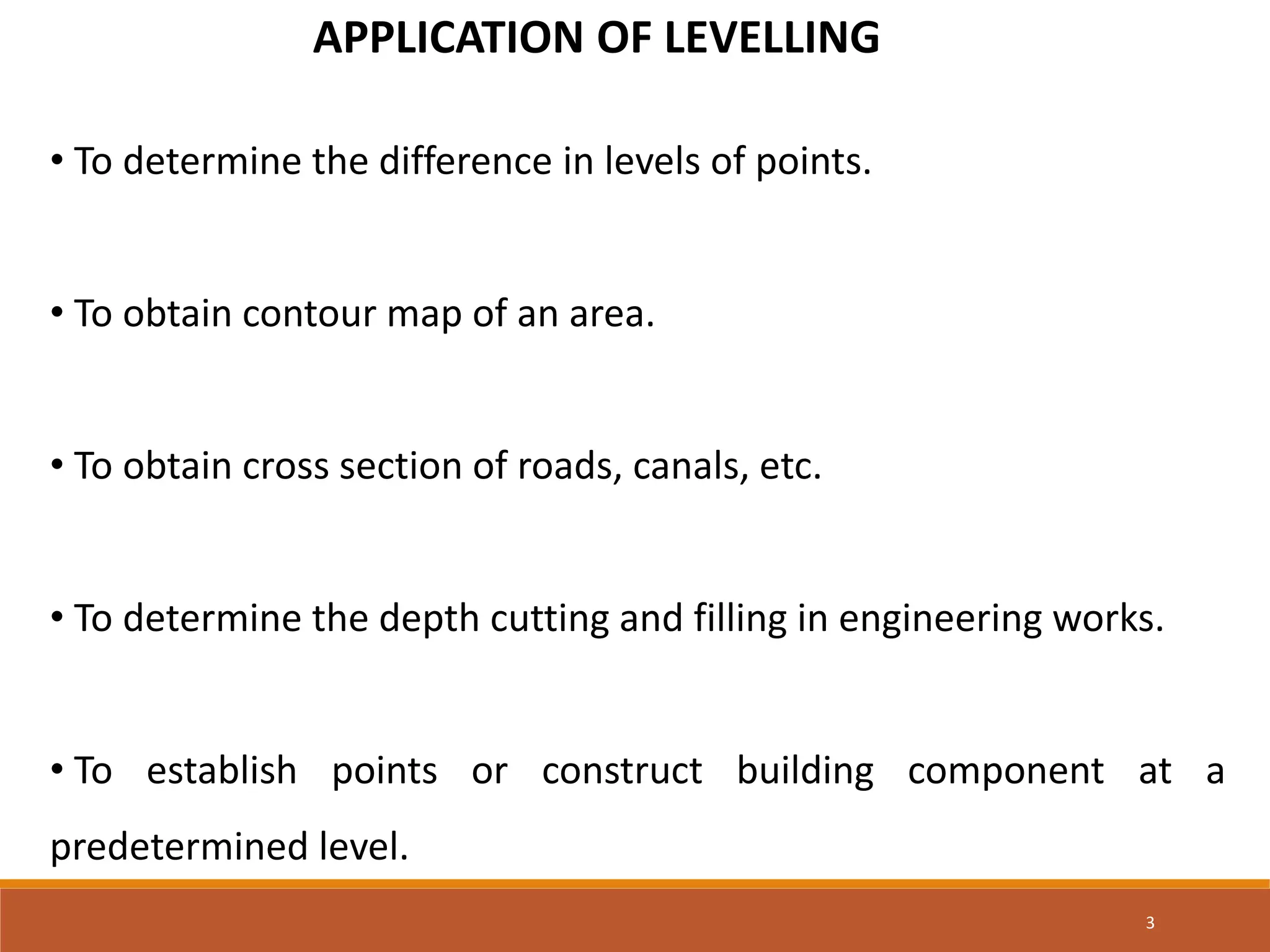
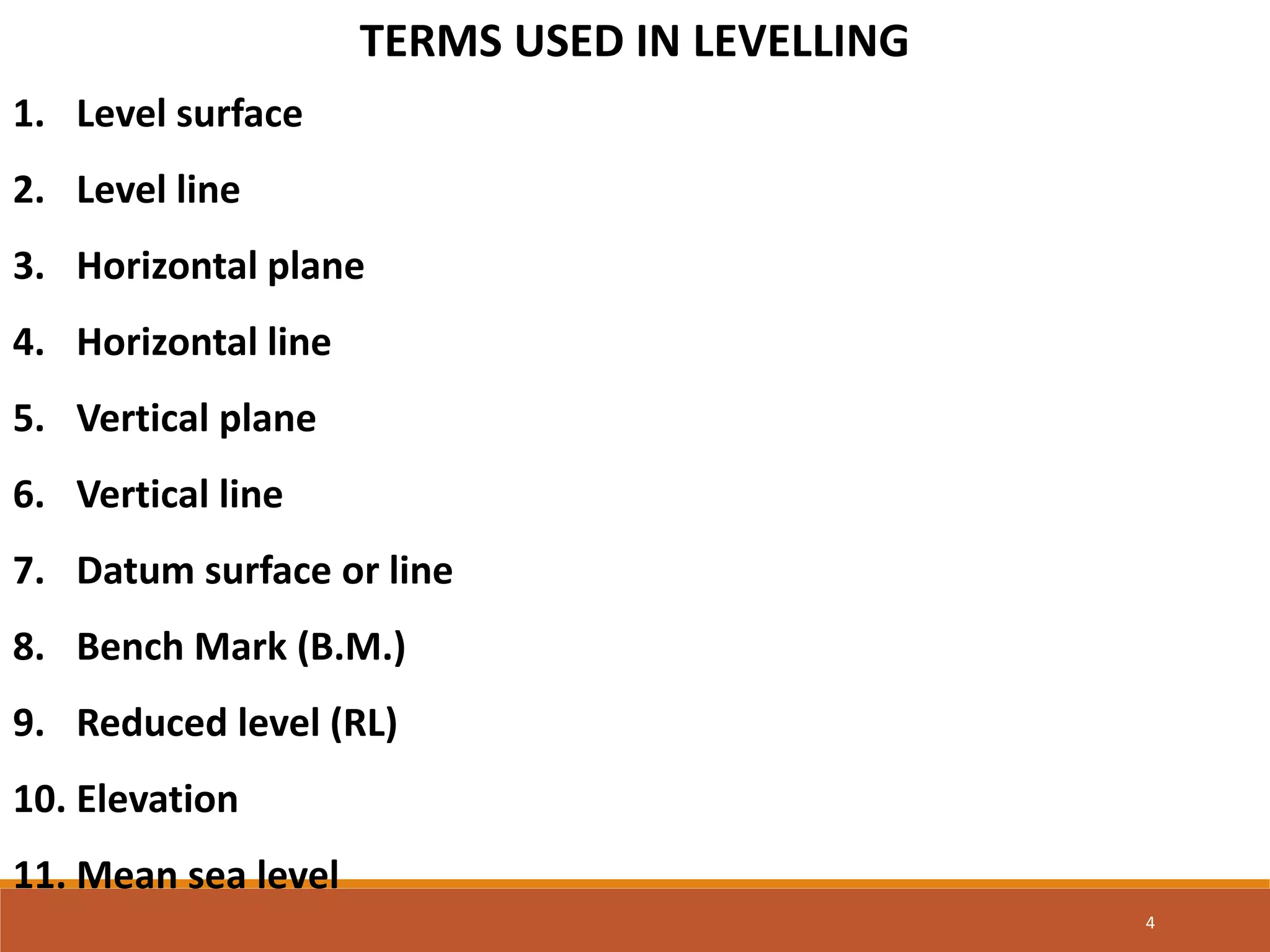
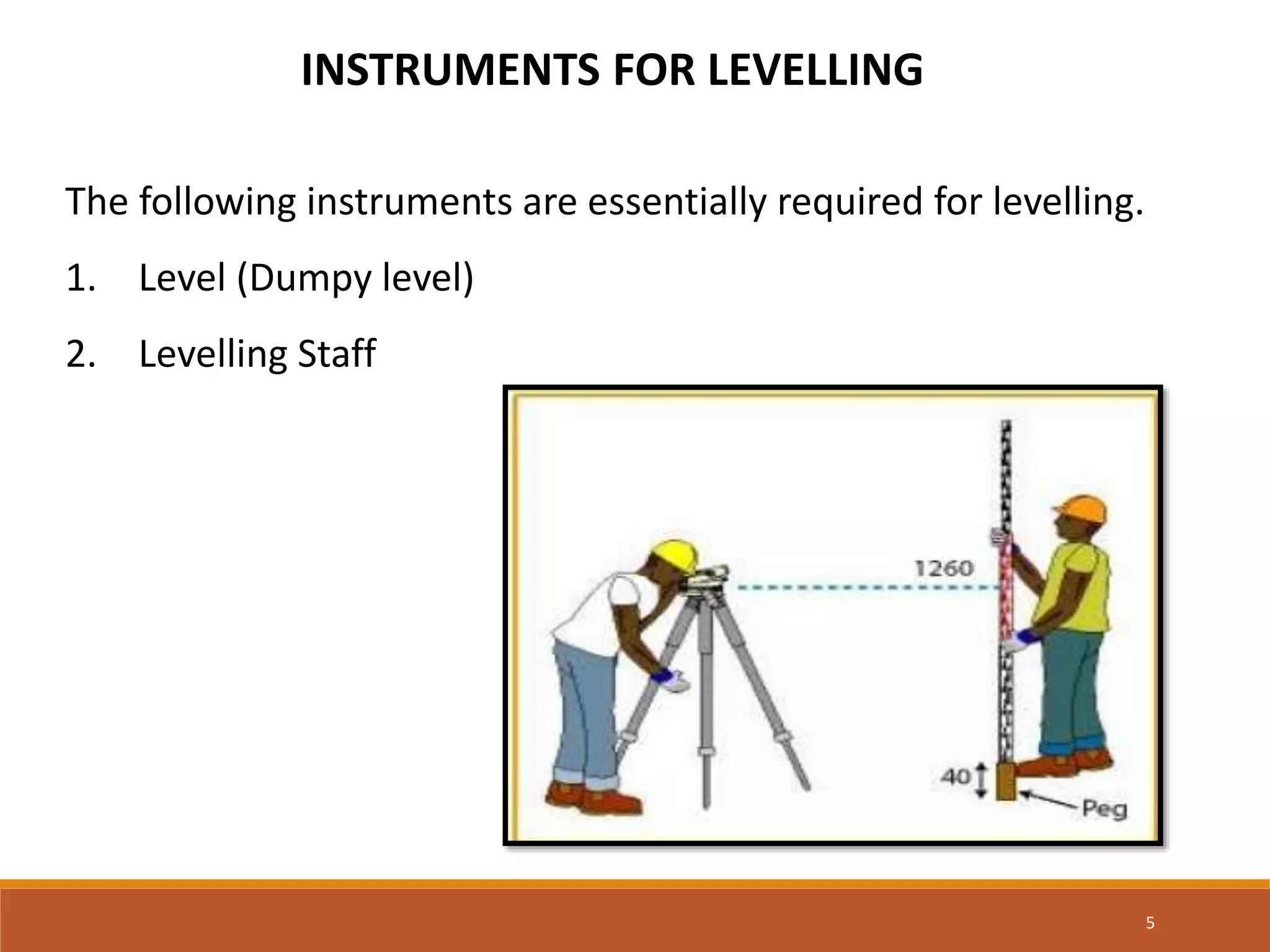
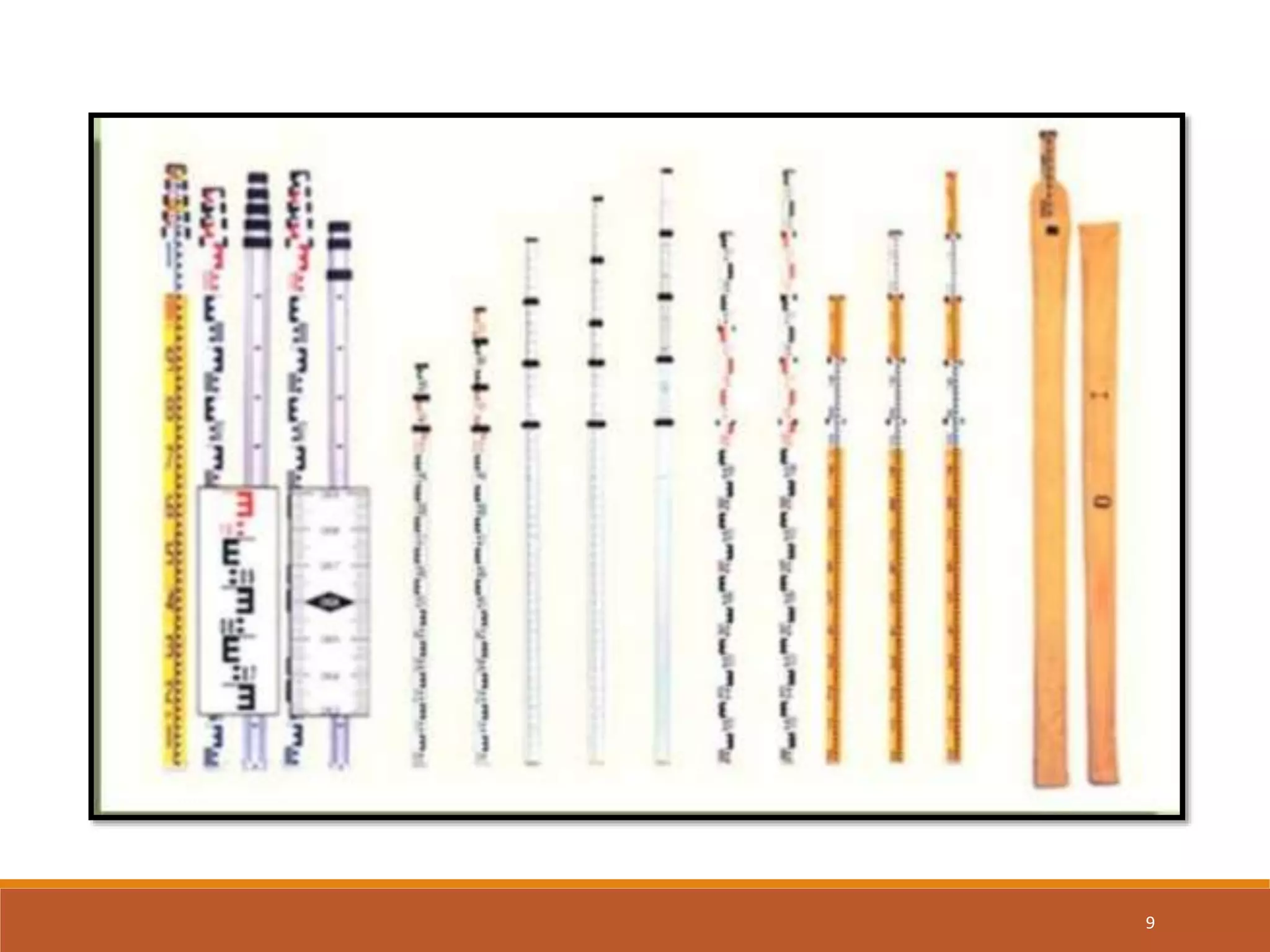
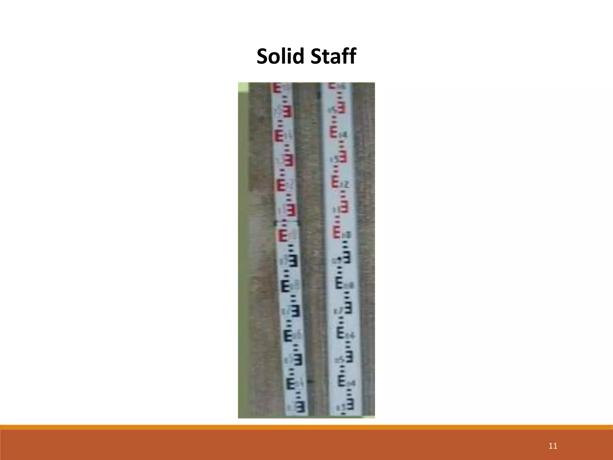
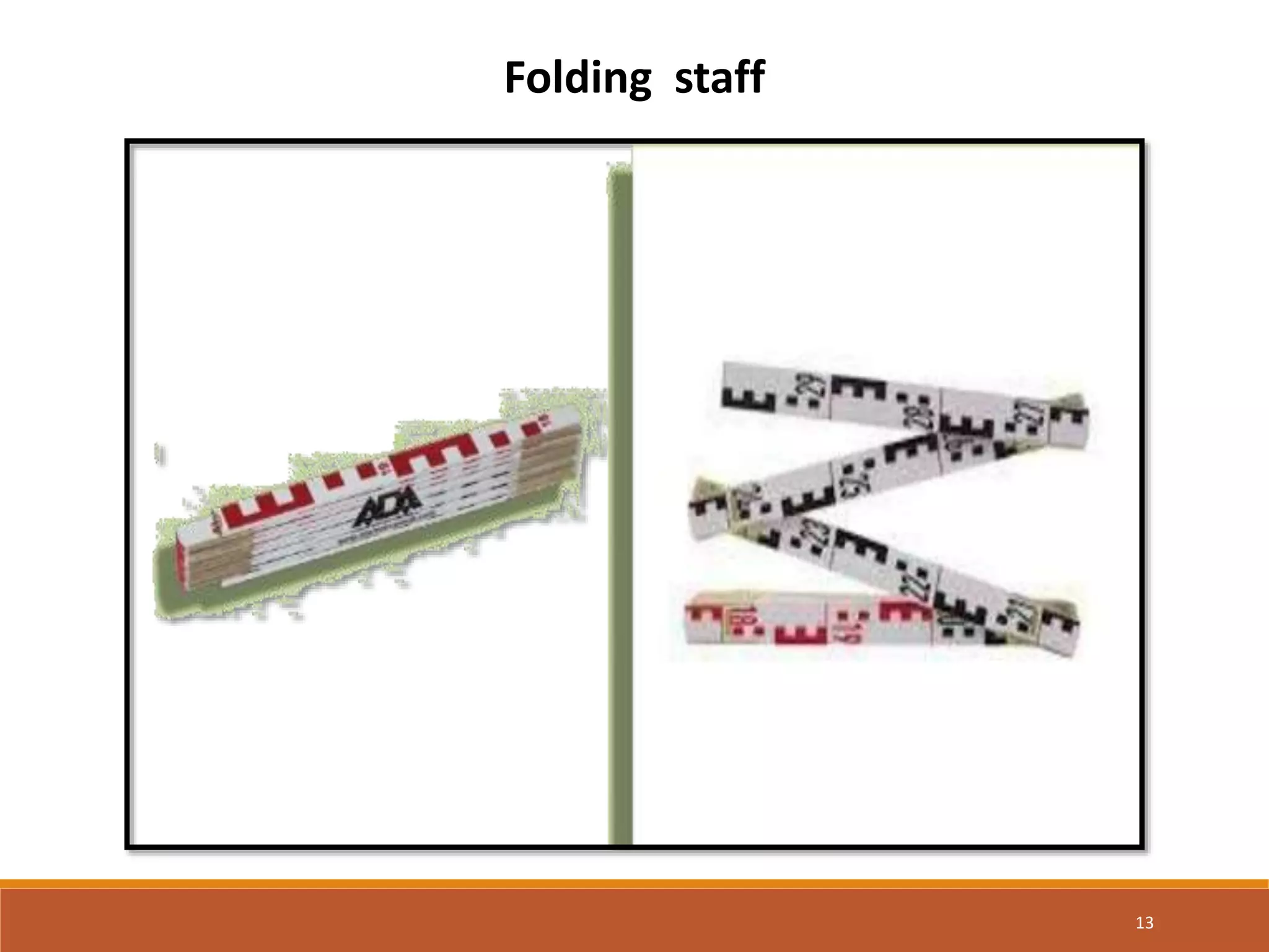
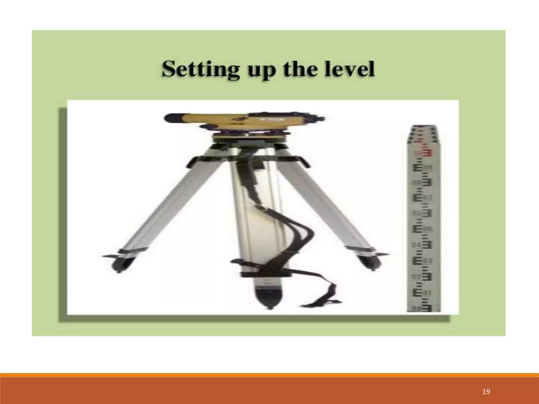
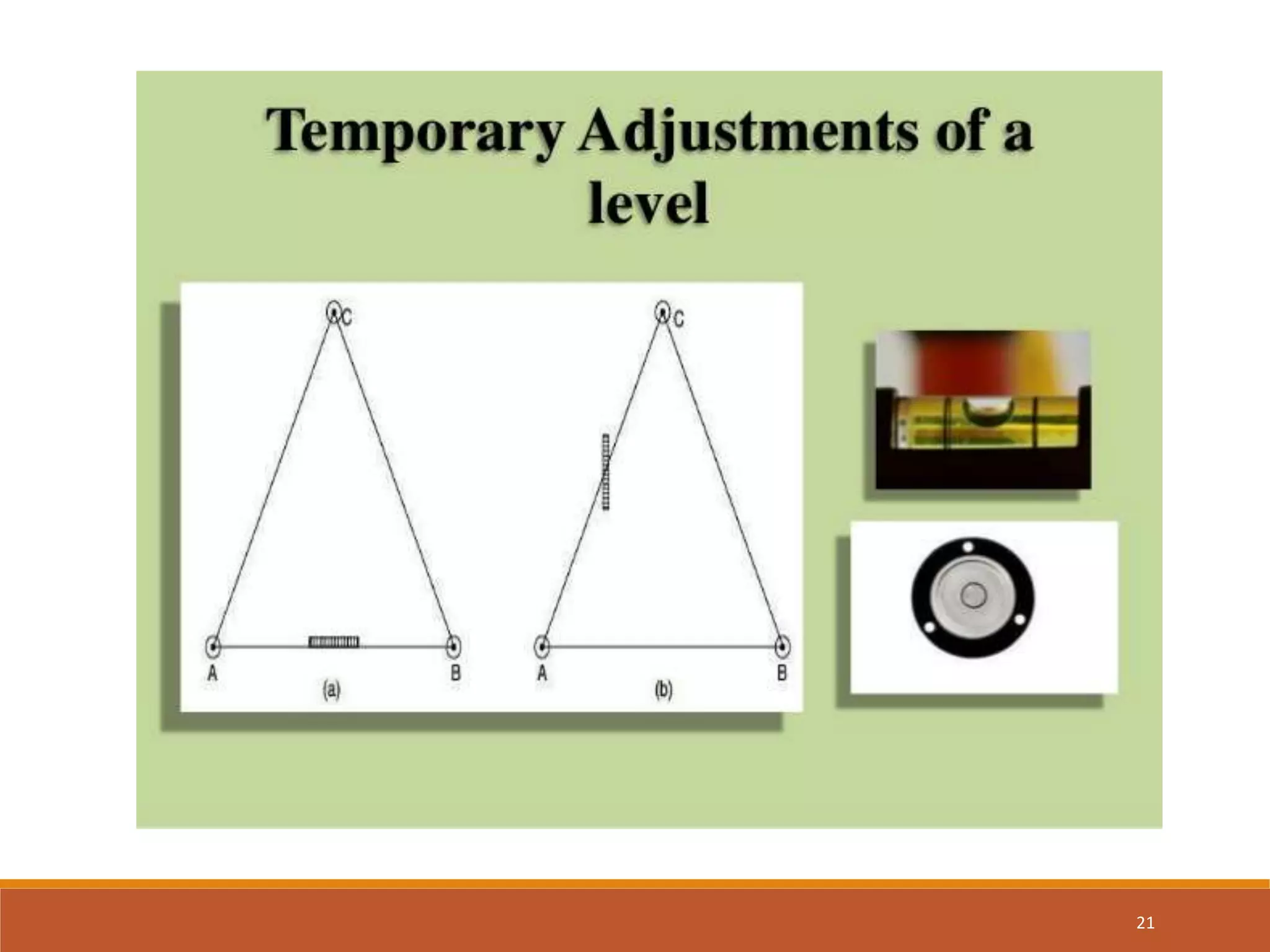
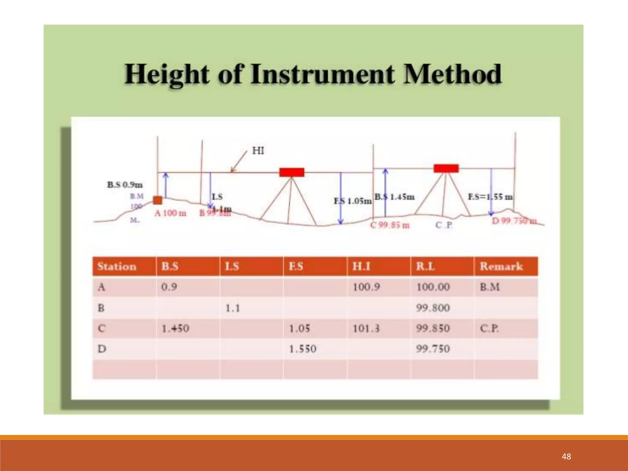
This document provides information on various topics related to leveling and contouring. It discusses the basic principles and methods of leveling, including the instruments used such as dumpy levels and staffs. It covers temporary adjustments, classifications of leveling, errors, reductions of levels, and benchmarks. The document also explains what contour lines are, contour intervals, characteristics of contours, and methods of contouring directly and indirectly.
Surveying is an important part of Civil engineering. Various part like theodolite, plane table surveying, computation of area and volume are useful for all university examination and other competitive examination
the presentation is about Field Astronomy, generally deals with astronomical terms & Co-ordinate system related to field astronomy. Astronomical terms like celestial sphere, Zenith, Nadir & Celestial pole/ equators all are included in these slides; rather than that Celestial latitude & longitude co-ordinate system, Altitude & azimuth co-ordinate system, declination & Right ascension co-ordinate system & Declination & hour angle co-ordinate system are explained in these slides.
Surveying Engineering
Traversing Practical part 1
Plane and Applied surveying 2
Report number(2)
• Report name :Gales Traverse Table(Horizontal angle
measurement (FL)of closed traversing
• Apparatus
• Theodolite Instrument
• Tripod
• Compass
• Pin
• Tape
• Range pole
Object
• To conducted survey work in a closed traversing and calculate
in depend coordinates and area calculation by coordinate rule.
Procedure Traverse;
Calculations Traverse .Dada Sheet and Table method work clock wise surveying
-Gales Traverse Table.
*Traverse Calculations
-Traverse Calculation.
-Coordinate conversions.
-Signs of Departures and Latitudes.
*Balancing latitude and departure
-Correction for ∆E& ∆N:
Bowditch adjustment or compass method
-The example…
-Vector components (pre-adjustment)
*The adjustment components
Prepared by:
Asst. Prof. Salar K.Hussein
Mr. Kamal Y.Abdullah
Asst.Lecturer. Dilveen H. Omar
Erbil Polytechnic University
Technical Engineering College
Civil Engineering Department
Compass surveying
Bearing
Whole circle bearing and reduced bearing
Conversion of bearings
Computation of angles
Declination and dip
Local attraction
Isogonic Lines
Agonic Lines
Detecting local attraction
For detecting local attraction it is necessary to take both fore bearing and back bearing for each line.
If the difference is exactly 180°, the two stations may be considered as not affected by local
attraction.
If difference is not 180°, better to go back to the previous station and check the fore bearing. If that
reading is same as earlier, it may be concluded that there is local attraction at one or both stations.
Contouring - Surveying...for civil Engineering and Architecture..Pramesh Hada
Contouring - Surveying...for civil Engineering and Architecture students. It contains all the syllabus according to Pokhara University, Nepal
---By Assistant Professor. Pramesh Hada
Nepal Engineering College
CHangunarayan, Bhaktapur
*Introduction
*Controls For Setting Out
*Horizontal control
*Vertical control
*SETTING OUT A BUILDING
*The equipment required for the job
*Method(1):-By using a Circumscribing Rectangle
*Method(2):- By using centre-line-rectangle
* Setting out of culverts
*SETTING OUT A TUNNEL
planning for smart cities
sustainable green building,
safety, security, disaster management, economy, cyber security, Project management.
AS PER GTU 7TH SEM SYLLABUS MODULE 2
Intelligent transport systems
Smart vehicles and fuels, GIS, GPS, Navigation system, traffic safety management,
mobility services, E-ticketing
AS PER GTU 7TH SEM SYLLABUS MODULE 3
Disaster Management can be defined as the organization and management of resources and responsibilities for dealing with all humanitarian aspects of emergencies, in particular preparedness, response and recovery in order to lessen the impact of disasters.
for the subject offered in GTU, BCT, ace, cm
module 4 demolition of the structure
for the 3rd sem & also for the 6th sem subject and for the master of construction management
for the subject offered in GTU in the final year (8th semester), construction management
final year
Module:- 5 project scheduling and resource leveling
June 3, 2024 Anti-Semitism Letter Sent to MIT President Kornbluth and MIT Cor...Levi Shapiro
Letter from the Congress of the United States regarding Anti-Semitism sent June 3rd to MIT President Sally Kornbluth, MIT Corp Chair, Mark Gorenberg
Dear Dr. Kornbluth and Mr. Gorenberg,
The US House of Representatives is deeply concerned by ongoing and pervasive acts of antisemitic
harassment and intimidation at the Massachusetts Institute of Technology (MIT). Failing to act decisively to ensure a safe learning environment for all students would be a grave dereliction of your responsibilities as President of MIT and Chair of the MIT Corporation.
This Congress will not stand idly by and allow an environment hostile to Jewish students to persist. The House believes that your institution is in violation of Title VI of the Civil Rights Act, and the inability or
unwillingness to rectify this violation through action requires accountability.
Postsecondary education is a unique opportunity for students to learn and have their ideas and beliefs challenged. However, universities receiving hundreds of millions of federal funds annually have denied
students that opportunity and have been hijacked to become venues for the promotion of terrorism, antisemitic harassment and intimidation, unlawful encampments, and in some cases, assaults and riots.
The House of Representatives will not countenance the use of federal funds to indoctrinate students into hateful, antisemitic, anti-American supporters of terrorism. Investigations into campus antisemitism by the Committee on Education and the Workforce and the Committee on Ways and Means have been expanded into a Congress-wide probe across all relevant jurisdictions to address this national crisis. The undersigned Committees will conduct oversight into the use of federal funds at MIT and its learning environment under authorities granted to each Committee.
• The Committee on Education and the Workforce has been investigating your institution since December 7, 2023. The Committee has broad jurisdiction over postsecondary education, including its compliance with Title VI of the Civil Rights Act, campus safety concerns over disruptions to the learning environment, and the awarding of federal student aid under the Higher Education Act.
• The Committee on Oversight and Accountability is investigating the sources of funding and other support flowing to groups espousing pro-Hamas propaganda and engaged in antisemitic harassment and intimidation of students. The Committee on Oversight and Accountability is the principal oversight committee of the US House of Representatives and has broad authority to investigate “any matter” at “any time” under House Rule X.
• The Committee on Ways and Means has been investigating several universities since November 15, 2023, when the Committee held a hearing entitled From Ivory Towers to Dark Corners: Investigating the Nexus Between Antisemitism, Tax-Exempt Universities, and Terror Financing. The Committee followed the hearing with letters to those institutions on January 10, 202
Synthetic Fiber Construction in lab .pptxPavel ( NSTU)
Synthetic fiber production is a fascinating and complex field that blends chemistry, engineering, and environmental science. By understanding these aspects, students can gain a comprehensive view of synthetic fiber production, its impact on society and the environment, and the potential for future innovations. Synthetic fibers play a crucial role in modern society, impacting various aspects of daily life, industry, and the environment. ynthetic fibers are integral to modern life, offering a range of benefits from cost-effectiveness and versatility to innovative applications and performance characteristics. While they pose environmental challenges, ongoing research and development aim to create more sustainable and eco-friendly alternatives. Understanding the importance of synthetic fibers helps in appreciating their role in the economy, industry, and daily life, while also emphasizing the need for sustainable practices and innovation.
Introduction to AI for Nonprofits with Tapp NetworkTechSoup
Dive into the world of AI! Experts Jon Hill and Tareq Monaur will guide you through AI's role in enhancing nonprofit websites and basic marketing strategies, making it easy to understand and apply.
Biological screening of herbal drugs: Introduction and Need for
Phyto-Pharmacological Screening, New Strategies for evaluating
Natural Products, In vitro evaluation techniques for Antioxidants, Antimicrobial and Anticancer drugs. In vivo evaluation techniques
for Anti-inflammatory, Antiulcer, Anticancer, Wound healing, Antidiabetic, Hepatoprotective, Cardio protective, Diuretics and
Antifertility, Toxicity studies as per OECD guidelines
Model Attribute Check Company Auto PropertyCeline George
In Odoo, the multi-company feature allows you to manage multiple companies within a single Odoo database instance. Each company can have its own configurations while still sharing common resources such as products, customers, and suppliers.
Macroeconomics- Movie Location
This will be used as part of your Personal Professional Portfolio once graded.
Objective:
Prepare a presentation or a paper using research, basic comparative analysis, data organization and application of economic information. You will make an informed assessment of an economic climate outside of the United States to accomplish an entertainment industry objective.
3. 3
• To determine the difference in levels of points.
• To obtain contour map of an area.
• To obtain cross section of roads, canals, etc.
• To determine the depth cutting and filling in engineering works.
• To establish points or construct building component at a
predetermined level.
APPLICATION OF LEVELLING
4. TERMS USED IN LEVELLING
1. Level surface
2. Level line
3. Horizontal plane
4. Horizontal line
5. Vertical plane
6. Vertical line
7. Datum surface or line
8. Bench Mark (B.M.)
9. Reduced level (RL)
10. Elevation
11. Mean sea level
4
5. INSTRUMENTS FOR LEVELLING
The following instruments are essentially required for levelling.
1. Level (Dumpy level)
2. Levelling Staff
5
7. 7
BASIC COMPONENTS OF DUMPY LEVEL
1. Tripod stand
2. Levelling head
3. Foot screws
4. Telescope
5. Bubble-tubes
6. Compass
7. Axis of the telescope
8. Line of collimation
8. 1. LEVELLING STAFFS
Levelling staffs are scales on which these distances are
measured.
Levelling staffs are of two types
1. Self Reading staff
2. Target staff
8
16. 16
Temporary Adjustments of a level
• These adjustments are performed at every setup of
instrument.
• Setting up of level
• Levelling of telescope
• Focusing of the eye peace
• Focusing of object glass
17. 17
• Temporary Adjustments of a level Setting up the level This
includes ..
• A) Fixing the instrument on tripod
• B) Levelling the instrument approximately by Tripod
20. 20
•Levelling is done with the help of foot screws. The purpose of
levelling is to make vertical axis truly vertical. It is done with
the help of foot screws.
• A) Place the telescope parallel to a pair of foot screw then
hold the foot screws between thumb and first finger and turn
them either inward or outward until the longitudinal bubble
comes in the centre.
• B)Turn the telescope through 90º so that it lies parallel to
third foot screw, turn the screw until the bubble comes in the
centre.
22. 22
Temporary Adjustments of a level Focusing the eye piece:-
• To focus the eye piece, hold a white paper in front of object
glass, and move the eye piece in or out till the cross hair are
distinctly seen.
•Focusing of object glass Direct the telescope to the levelling
staff and on looking through the telescope, turn the focusing
screw till the image appears clear and sharp.
25. 25
Simple Levelling
• It is the simplest method used, when it is required to find the
difference in elevation between 2 points.
26. 26
Differential Levelling
• This method is used to find the difference in the elevation
between points if they are too far apart or the difference in
elevation between them is too much.
28. 28
Fly Levelling
• Fly levelling is just like differential levelling carried out to check
the accuracy of levelling work. In fly levelling only B.S. and F.S. are
taken.
29. 29
Check levelling
• This kind of levelling is carried out to check the accuracy of
work. It is done at the end of the days work in the form of fly
levelling to connect the finishing point and starting point.
Profile levelling or L-Section
• This method is used for taking levels along the centre line of any
alignment like road, railway canal etc. The object is to determine
the undulations of the ground surface along the alignment.
32. 32
Cross-Sectioning
• This operation is carried out perpendicular to alignment at
an interval of 10, 20 ,30, 40 m. The idea is to make an
estimate of earthwork.
34. 34
• Reciprocal Levelling:-
• This method is adopted to accurately determine the difference of level
between two points which are far apart. It is also used when it is not
possible to setup level in midway between two points.
• Let A and B be the two points on opposite banks of a river. It is
required to find out the level difference between A&B.
• Setup the level very near to A and take the reading at A and B let the
reading be a1 and b1.
• Shift the level and setup very near to B and observe A and B to get
reading a2 and b2.
• Let d is the true difference of level between A and B, and e=error due
to curvature, refraction and imperfect adjustment.
36. 36
Reciprocal Levelling
• Thus to eliminate the error take an average of the difference in
elevation taken from 2 points.
• i.e. from A the true difference will be d= (b 1- a1)-e
• From B the difference will be d= (b2-a2)+ e
• Adding these two eqn to eliminate e, we get
• Therefore d={(b1-a1)+ (b2-a2)}/2
39. Bench Marks
Bench mark is a point of known elevation. There are 4 kinds of
bench marks.
• GTS (Great trigonometrically survey bench mark)
• Permanent bench mark
• Arbitrary bench mark
• Temporary bench mark
39
40. GTS Bench Mark
• They are the bench marks established with very high degree of
precision at regular intervals by the survey of India Department
all over the country Their position and R.Ls values above mean
seal level which was earlier located at Karachi and now it is taken
at Bombay High, Mumbai and is given in catalogue formed by
the department.
40
42. Permanent Bench Mark
• Permanent bench marks are fixed in between GTS
benchmarks by govt. agencies such as railways, PWD, etc.
This benchmarks are written on permanent objects such as
milestones, culverts, bridges etc their value are clearly
written and their position are recorded for future reference.
42
44. Arbitrary Bench Marks
• These are reference points whose R.L.s are arbitrarily assumed.
They are used in small works such bench mark may be assumed
as 100 or 50 m.
Temporary Bench Marks
• They are the reference points established during the levelling
operations when there is a break in work, or at the end of day’s
work the value of reduced levels are marked on some
permanent objects such as stones, trees etc.
44
47. 47
Methods of Reducing Levels
Height of Instrument Method:-
• This method consist of finding H.I. for every setup of
instrument, and then obtaining the R.L. of point of reference with
respect to H.I.
49. 49
Rise and Fall Method:-
• This method consist of determining the difference of level
between consecutive points by comparing each point with
immediate preceding point.
51. 51
Errors in Levelling
The following are the different sources of Errors.
• Personal Error
• The Instruments may not be levelled
• The focusing of eye piece and objective glass may not be
perfect
• The parallax may not be eliminated
• The position of staff may have changed
• Entry and recording in the field book may not be correct
• The staff may not be fully extended, may not be held vertical.
52. 52
Errors in Levelling Instrumental Error :-
• The Permanent adjustment of the instrument may not be
perfect. That is the line of collimation may not be horizontal line.
• The internal arrangement of focusing tube may not be correct
• The graduation of the staff may not be perfect
• Defective bubble tube, if the bubble tube is sluggish, it may
apparently be in the mid-position even though the bubble line is
not horizontal.
53. 53
Errors in Levelling Errors due to Natural Causes
• The Curvature of the Earth may affect the staff readings
when the distance of sight is long.
• The effect of refraction may cause a wrong staff reading
• There are some errors in staff readings due to high velocity
wind
54. 54
Common errors in Leveling
• Foresight and back sight not being taken on exactly the same point
• Reading the staff upward instead of downward
• Reading of wrong number of metre and decimeter
• Entering backsight in F.S and vice versa
• The leveling staff not being fully extended.
55. 55
Curvature Correction
• For long sights the curvature of earth can effect staff readings. The
line of sight is horizontal but the level line is curved and parallel to
the mean spheroidal surface of the earth.
• The vertical distance between the line of sight and level line at
particular place is called the curvature correction.
• The effect of curvature is to cause the object sighted to appear
lower than they really are.
• Curvature correction is always Subtractive(-)
• True staff reading=(Observed staff reading- 0.0785D2)m
• Where D= distance in Km
58. 58
Refraction
• The ray of light pass through layers of air of different densities
and refractor bent down. The effect of refraction is to make the
object appear higher then they really are. Refraction varies
considerably with climate conditions. However it is taken as,
• Cr=0.0112 D2m(+)
• Refraction is always additive
• True staff reading =Observed staff Reading+ Refraction
correction.
61. 61
Contour Line
• A contour line may be defined as “An imaginary line passing
through points of equal reduced levels”. A contour line may also
be defined “as the intersection of a level surface with the surface
of the earth”. Thus, contour lines on a plan illustrates the
topography of the area.
• For ex a contour of 90 m indicates that all the points on this line
have RL of 90 m. Similarly, in a contour of 89 m all the points have
RL of 89 m and so on.
63. 63
Contour Interval
• The vertical distance between two consecutive contours is
known as a contour interval.
• For ex, a map indicates contour lines of 90 m, 89 m, 88 m and so
on, the contour interval is 1m.
• This interval depends upon the following factors: • The nature of
the ground (i.e. . Whether flat or steep) • The scale of the map, and
The purpose of the survey.
65. 65
Contour Interval
• Contour intervals for flat ground are generally small, e.g.. 0.25 m,
0.5 m, 0.75 m
• The contour interval for a steep slope in a hilly area is generally
greater, e.g.. 5 m, 10 m, 15 m, etc.
• Again, for a small scale map, the interval may be of 1 m, 2 m, 3 m,
etc.
• Contour interval is kept large up to 2 m for projects such as
highways and railways, whereas it is kept as small as 0.5 m for
measurement of earthwork, building sites, dams, etc.
66. 66
Horizontal Equivalent
• The horizontal distance between any two consecutive
contours is known as horizontal equivalent. It is not constant. It
varies from point to point depending upon the steepness of the
ground. Steeper the ground, lesser is the horizontal equivalent.
67. 67
Use of Contour Map
• Contour maps provide valuable information about the topography
of the area, whether it is flat, undulating or mountainoueous. The
nature of the ground surface of an area can be understood by
studying a contour map.
• The following are the specific uses of the contour map.
• To select sites for engineering projects such as roads, canals,
railways.
• To find the possible route of communication between different
places.
68. 68
• To ascertain the indivisibility of stations.
• To ascertain the profile of the ground surface along any direction.
• A suitable route for given gradient can be marked on the map. To
estimate the quantity of cutting, filling, etc.
• To know the drainage characteristics of the area. It helps to select
sites for culverts, bridges, drainage system.
•The capacity of a reservoir and the area of submergence can be
computed.
70. 70
Characteristics of Contours
• Since every point on a contour line has the same elevation, a
contour map with a constant interval portrays the conformation
of the ground in a characteristics manner.
• The knowledge of contour characteristics helps in identifying the
natural features of the area from the given map and in avoiding
mistakes in plotting the contours correctly.
72. 72
Characteristics of Contours
• The following characteristics help in plotting or reading a
constant map.
• All the points on a contour line have the same elevation. The
elevations of the contour are indicated either by inserting the
figure in a break in respective contour or printed close to the
contour.
• Two contour lines do not intersect with each other.
• Contour lines always from a closed circuit. But these lines may be
within or outside the limit of the map.
• Contour do not have sharp turning.
73. 73
Characteristics of Contours
• The contour lines are closer near the top of a hill or high ground
and wide apart near the foot. This indicates a very steep slope
towards the peak and a flatter slope towards the foot.
• The contour lines are closer near the bank of a pond or
depression and wide towards the centre. This indicates a steep
slope near the bank and a flatter slope at the centre.
• Uniformly spaced contour lines indicate a uniform slope.
74. 74
Characteristics of Contours
• A series of closed contour always indicates a depression or summit.
The lower values being inside the loop indicates a depression and
the higher values being inside the loop indicates a summit. (Hillock)
• Contour deflect uphill at valley lines and downhill at the ridge lines.
Contour lines in U-shape cross a ridge and V- shape cross a valley at
ridge angles. The concavity in contour lines is towards higher ground
in the case of ridge and towards lower ground in the case of valley.
75. 75
• Contour lines meeting at a point indicate a vertical cliff.
• Contour lines cannot cross one another, except in the case of
an overhanging cliff. But the overhanging portion must be shown
by a dotted line.
80. 80
Methods of Contouring
• Contouring requires the planimetric position of the points
whose elevation have been determined by levelling.
• The methods of locating contours, therefore depending upon
the instruments used to determine the horizontal as well as
vertical position of several points in the area.
81. 81
Methods of Contouring
• Broadly, the method can be divided into the
following two classes.
1. Direct methods
2. Indirect methods
82. 82
Direct Method
• In the direct method of contouring, the reduced level of various
selected points on a contour line are obtained and their positions are
located. The contours are then drawn by joining these points. It is a very
accurate method but it is slow and tedious.
• This method is employed only for small area where superior accuracy
is demanded. The method of locating contours directly consists of
horizontal and vertical control. The horizontal control for a small area
can be exercised by a chain or tape and a large area by compass,
theodolite or plane table. For vertical control either a level and staff or a
hand level may be used.
84. 84
By Level and Staff
• The method consists of locating a series of points on the ground
having the same elevation by using a level and leveling staff.
Instrument is setup in such a way that number of readings can be
taken from the area to be surveyed.
• The instrument is set up and RL of HI is determined from the nearest
benchmark. For a particular contour value, the staff reading is worked
out. A series of points having the same staff reading is worked out, and
thus the same elevations are plotted and joined by a smooth curve.
86. 86
By Hand Level
• The principle used is the same as that used in the method
using a level and staff. Instead of the hand level, an abbey level
may also be used. However this method is very rapid and is
preferred for certain works.
88. 88
Indirect Methods
• Indirect methods are less expensive, less time consuming and
less tedious as compared with the direct methods. These
methods are commonly employed in small scale survey of large
areas.
89. 89
Methods of Contouring
• There are three different ways of employing the indirect
methods of contouring .
• (i) Grid Method
• (ii) Cross-Sectional Method
• (iii) Radial line method or Tachometric method
90. 90
Grid Method
• If the area is not large, it is divided into a grid or series of squares. The
grid size may vary from 5m x 5 m to 25 m x 25 m depending upon the
nature of the ground, the contour interval and the scale of the map. The
grid corner are marked on the ground and spot levels of these corners
are then determined by normal method of leveling using a level.
• The grid is plotted to the scale of the map and the spot levels of the
grid corners are entered, the contours of desired values are then locked
by interpolation. This method is very suitable for a small open area
where contour are required at a closed vertical interval.
92. 92
Cross-Sectioning Method
• In this method, suitable spaced cross –sections are projected on
either side of the centre line of the area. Several points are chosen
at reasonable distances on either sides. The observations are made
in the usual manner with a level.
• The cross- section lines are plotted to the scale, the points on
these lines are marked and reduced levels are entered. The
contours of desired values are then located by interpolation. This
method is suitable for road, railway and canal survey.
94. 94
Radial Line Method or Tachometric Method
• In this method, a number of radial lines are set out at known angular
interval (i.e. 15 0 or 30 0) at each station. The point are selected on a
line depend on the nature of the ground surface. Instead of the level, a
tachometer may be used.
•The observations are taken on the staff stations and elevations and
distances are then calculated. A traverse and radial lines are plotted to
the scale RLs of the point entered. The contour of desired values are
then located by interpolation . This method is convenient in hilly area.
96. 96
Comparison of direct and Indirect methods of contouring
Direct Method Indirect Method
Most accurate but slow and
tedious
Not so accurate but rapid and
less tedious
Expensive Cheaper
Not suitable for hilly area Suitable for hilly area
During the work calculations
can be done
Calculations are not required in
the field
Calculation can not be checked
after contouring
Calculation can be checked as
and when required
97. 97
Interpolation of Contours
• The process of locating the contours proportionately between
the plotted point is termed interpolation may be done by:
1. Estimation
2. Arithmetical Calculation
3. Graphical Method
98. 98
Estimation
• The points on the required contour are located by eye
judgment or estimation between points whose elevations are
already known.
•This method is good for small scale maps. It is assumed that
slope between the ground points is uniform.
99. 99
Arithmetic Calculations
• This methods is used when high accuracy is required and scale
of the map is of intermediate or large.
• In this method the distances between two points of known
elevation are accurately measured. Then with the help of
arithmetic calculations, the positions of the required elevation
points are computed.
100. 100
Graphical Method
• When high accuracy is required and many interpolation are to
be made, this method of plotting contours proves to be most
rapid and convenient. For this purpose tracing paper is used.
101. 101
Plotting of a Contour Map
• Before plotting the contour map, suitable scale is selected.
• e.g. 1 cm = 1 m, 1 cm = 2 m, 1 cm = 2.5 m, 1 cm = 4 m or 1 cm = 5
m etc. Here 1 cm = 2m is selected.
• A horizontal line is drawn as the centre line
• The chainages are marked along the horizontal line according to
the scale.
• Ground levels are written from the level book according to the
chainage.
102. 102
• The cross-section (L/s and R/S) are also plotted (perpendicular lines)
at each of the chainage.
• By interpolation contours are joined by smooth curves keeping in
mind the characteristics of contour.
• First find out maximum and minimum RL values and then first plot
full values contour lines i.e.. 47 , 48, 49 etc. Contour interval is 1 m.
After plotting these contour lines reduces contour interval and it is
taken 0.5 m and contour lines i.e. 47.5, 48.5, 49.5 etc are plotted.
Contour lines are then inked.