Download to read offline


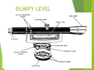
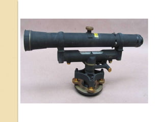
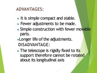


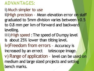
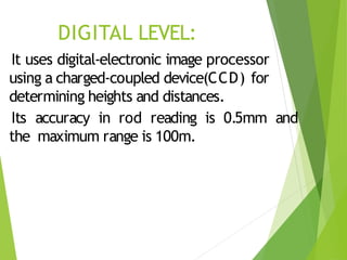
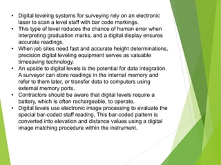
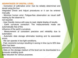
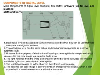

This document discusses different types of levels used in engineering projects. It provides details on dumpy levels, tilting levels, automatic levels, and digital levels. Dumpy levels have a rigidly fixed telescope but are simple and stable. Tilting levels allow the telescope to tilt for precise work. Automatic levels have a compensator to keep the line of sight horizontal. Digital levels use electronic image processing to determine heights and distances from a barcoded staff, reducing human error and allowing data transfer. Accurate elevation determination is important for engineering projects.