


![Rolling Resistance
When tire penetration is known, an approximate rolling
resistance value for a wheeled vehicle can be calculated . . .
RR = [40 + (30 * TP)] * GVW
Where:
RR = Rolling resistance in pounds
TP = Tire penetration in inches
GVW = Gross vehicle weight intons](https://image.slidesharecdn.com/che-10engineeringfundamental-200318050503/85/Che-10-engineering-fundamental-24-320.jpg)


![EXAMPLE 4-1
• Solution
Rolling resistance factor = 40 + (30 × 2) =100 lb/ton
[= 20 + (6 × 5) =50 kg/t]
Rolling resistance = 100 (lb/ton) × 100 (tons) = 10,000 lb
[= 50 (kg/t) × 91 (t) = 4550 kg]
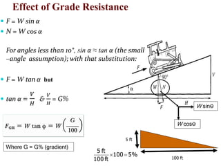
(a) Grade resistance = 100 (tons) × 2000 (lb/ton) × 0.05
= 10,000 lb
[= 91 (t) x 1000 (kg/t) × 0.05 =4550 kg]
Total resistance = 10,000 lb + 10,000 lb = 20,000 lb
[= 4550 kg + 4550 kg = 9100 kg]](https://image.slidesharecdn.com/che-10engineeringfundamental-200318050503/85/Che-10-engineering-fundamental-46-320.jpg)
![EXAMPLE 4-1
Effective grade =5 + 100/20 =10%
(b) Grade resistance =100 (tons) × 2000(lb/ton)× (-
0.05) = -10,000 lb
[= 91 (t) × 1000 (kg/t) x (-0.05) =-4550 kg]
Total resistance = -10,000 lb + 10,000 lb = 0 lb
[= -4550 kg + 4550 kg = 0 kg)
Effective grade = -5 + 100/20 = 0%
[= -5 + 50/10 = 0%]](https://image.slidesharecdn.com/che-10engineeringfundamental-200318050503/85/Che-10-engineering-fundamental-47-320.jpg)

![EXAMPLE 4-2
• Solution
Rolling resistance (neglect crawler) = 100 000 (lb)
/2000 (lb/ton) × 100 (lb/ton) = 5000 lb
[=45.5 (t) × 50 (kg/t) =2275kg]
Grade resistance = 180,000 × 0.04 = 7200 lb (4-6A)
[= 81.5 × 1000 kg/t × 0.04 = 3260 kg] (4-6B)
Total resistance = 5000 + 7200 = 12,200 lb
[= 2275 + 3260 = 5535 kg] (4-2)](https://image.slidesharecdn.com/che-10engineeringfundamental-200318050503/85/Che-10-engineering-fundamental-49-320.jpg)


![EXAMPLE 4-3
• Solution
Derating factor = 3 × [(10000 – 3000)/1000]
= 21% (4-8A)
[ = (3050 915)/102 =21%] (4-8B)
Percent rated power available=100 21 = 79%
Maximum available power = 40,000 × 0.79
= 31,600 lb
[ = 18160 × 0.79 = 14346 kg]](https://image.slidesharecdn.com/che-10engineeringfundamental-200318050503/85/Che-10-engineering-fundamental-60-320.jpg)
![EXAMPLE 4-3
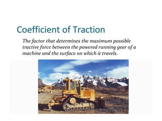
Coefficient of traction =0.45 (Table 4-2)
Maximum usable pull =0.45 × 44,000 = 19,800lb
(4-9)
[= 0.45 × 20000 = 9000 kg]](https://image.slidesharecdn.com/che-10engineeringfundamental-200318050503/85/Che-10-engineering-fundamental-61-320.jpg)


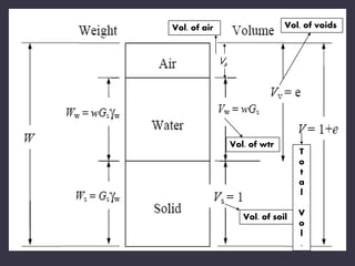
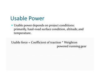
The document discusses selecting equipment for earthmoving projects based on analyzing the mechanical capabilities of machines and the properties of materials to be handled. It emphasizes that the contractor must choose equipment that can economically relocate and process bulk materials. Key factors in the decision process include the task properties of the material, and matching the machine's abilities. The engineer must calculate required power by considering rolling resistance and grade resistance to determine if a machine is suitable.


![Geotechnical Engineering-II [Lec #11: Settlement Computation]](https://cdn.slidesharecdn.com/ss_thumbnails/11-181020124840-thumbnail.jpg?width=640&height=640&fit=bounds)


![Geotechnical Engineering-II [Lec #9+10: Westergaard Theory]](https://cdn.slidesharecdn.com/ss_thumbnails/9-181020124827-thumbnail.jpg?width=640&height=640&fit=bounds)

![Geotechnical Engineering-I [Lec #24: Soil Permeability - II]](https://cdn.slidesharecdn.com/ss_thumbnails/24-180924141149-thumbnail.jpg?width=640&height=640&fit=bounds)


![Geotechnical Engineering-II [Lec #27: Infinite Slope Stability Analysis]](https://cdn.slidesharecdn.com/ss_thumbnails/27-181125070251-thumbnail.jpg?width=640&height=640&fit=bounds)

![Geotechnical Engineering-I [Lec #3: Phase Relationships]](https://cdn.slidesharecdn.com/ss_thumbnails/3-180923175732-thumbnail.jpg?width=640&height=640&fit=bounds)


