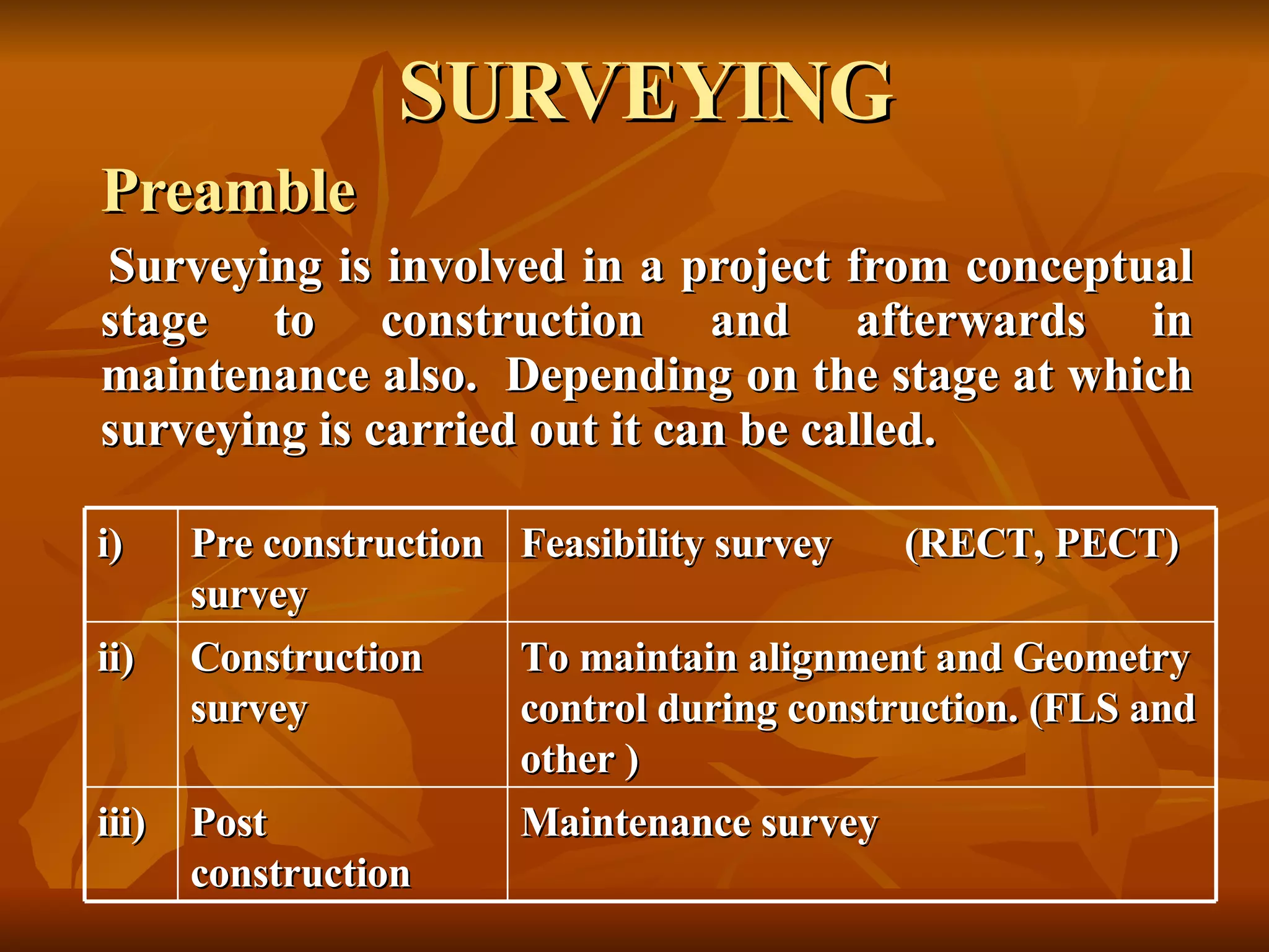
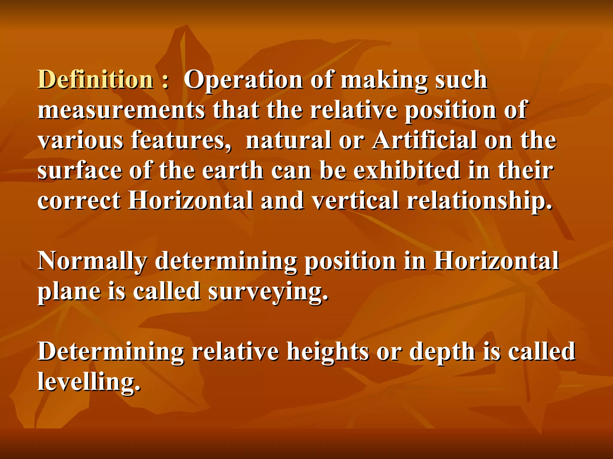
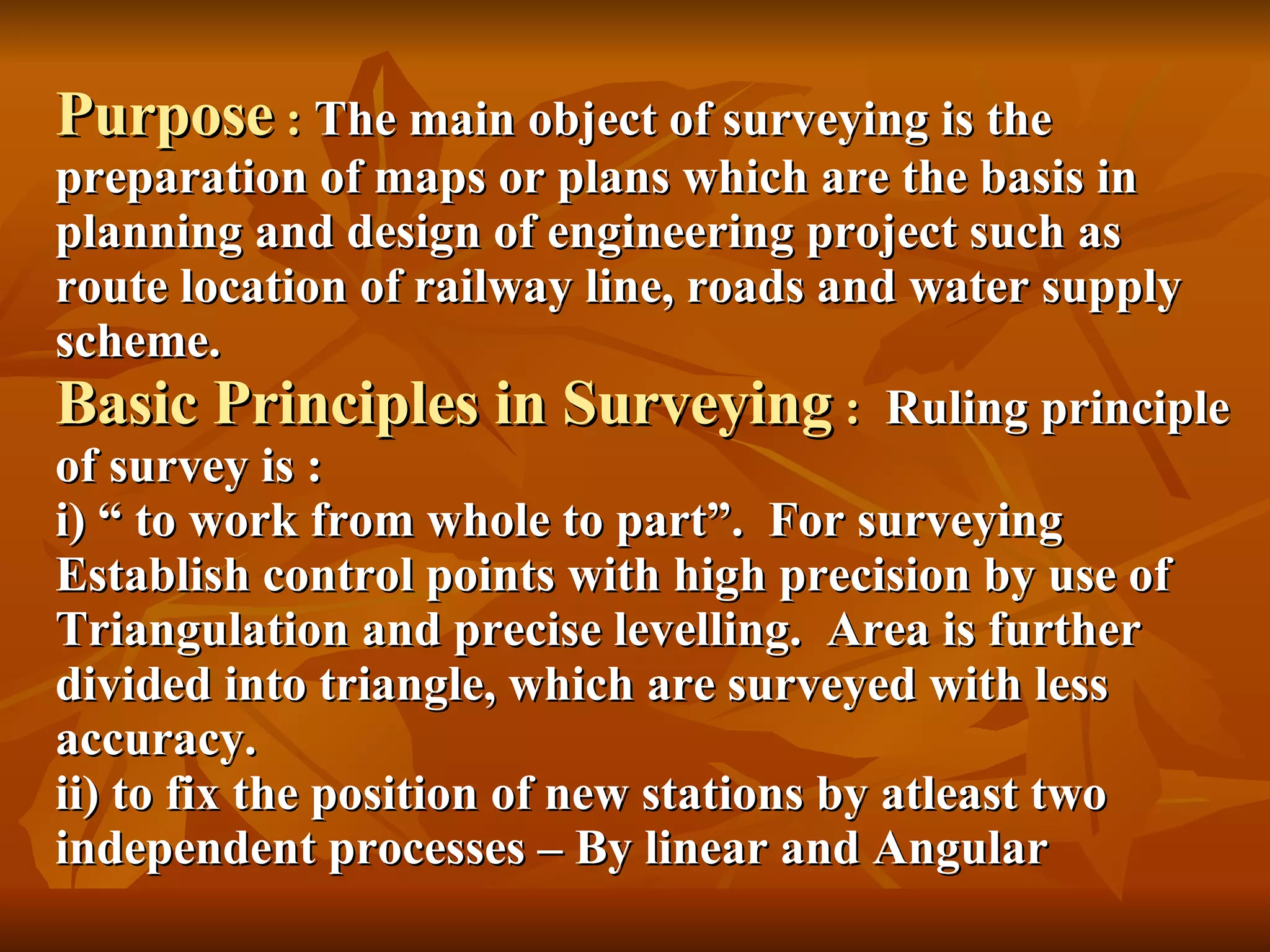
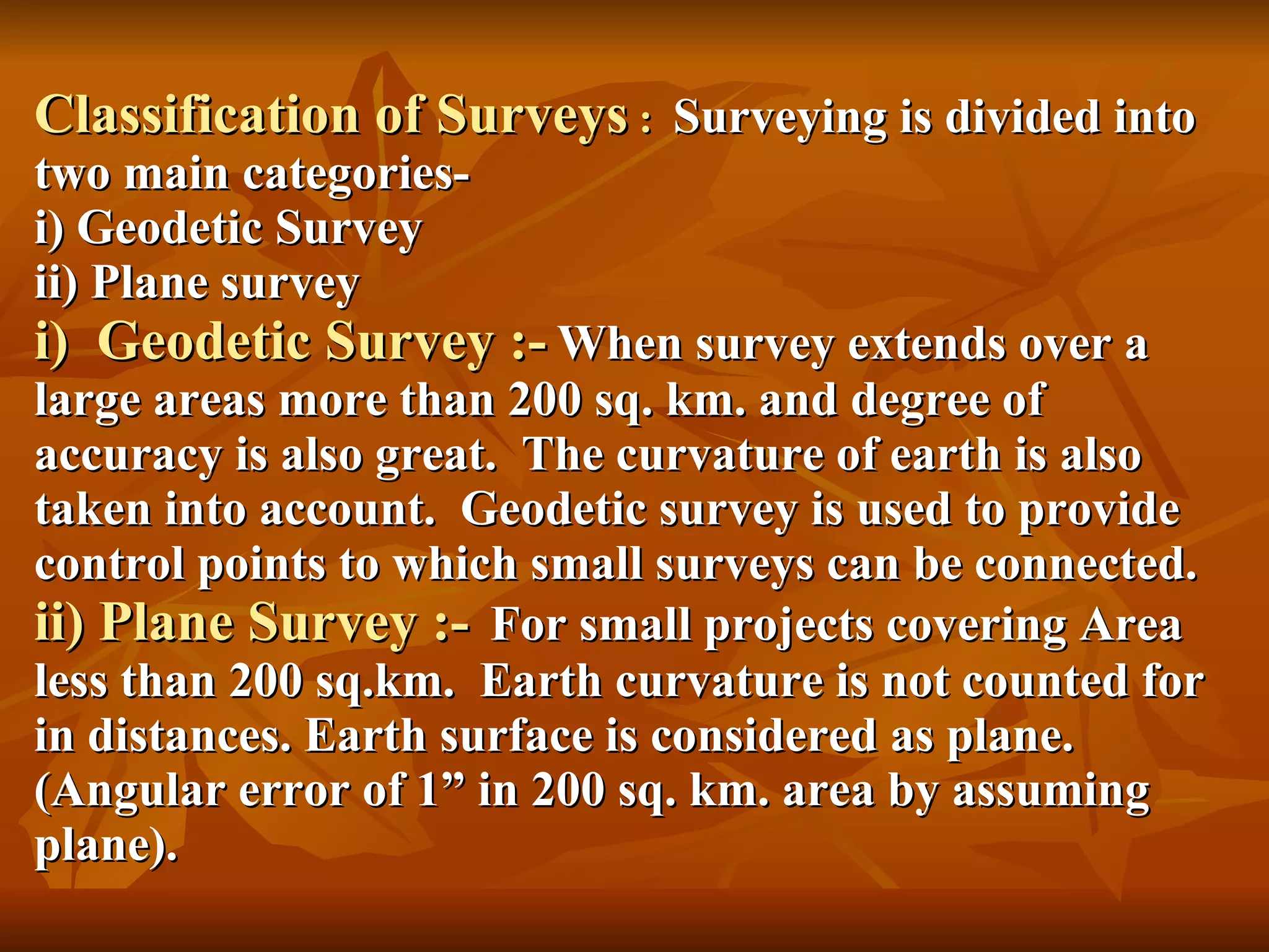
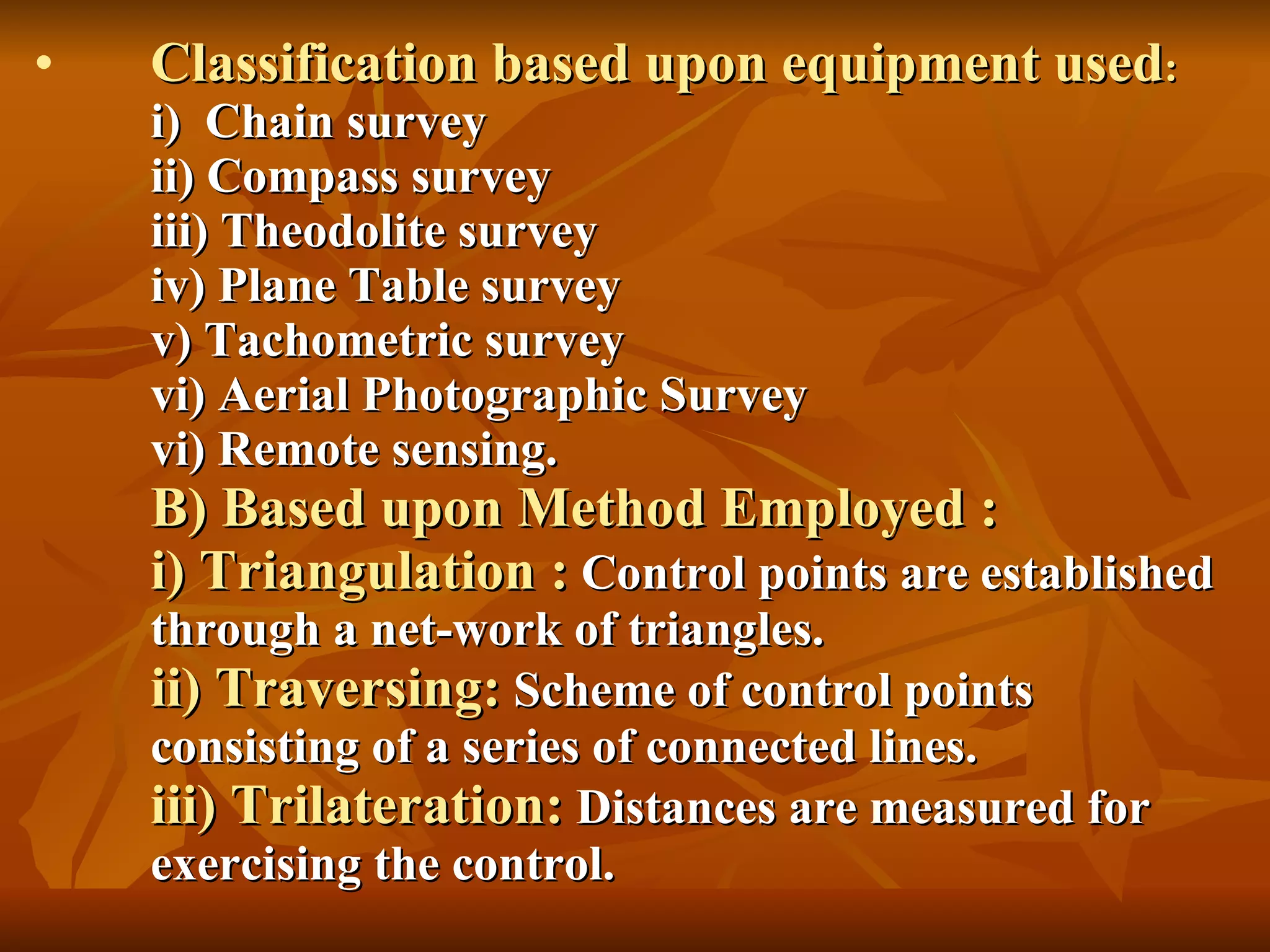
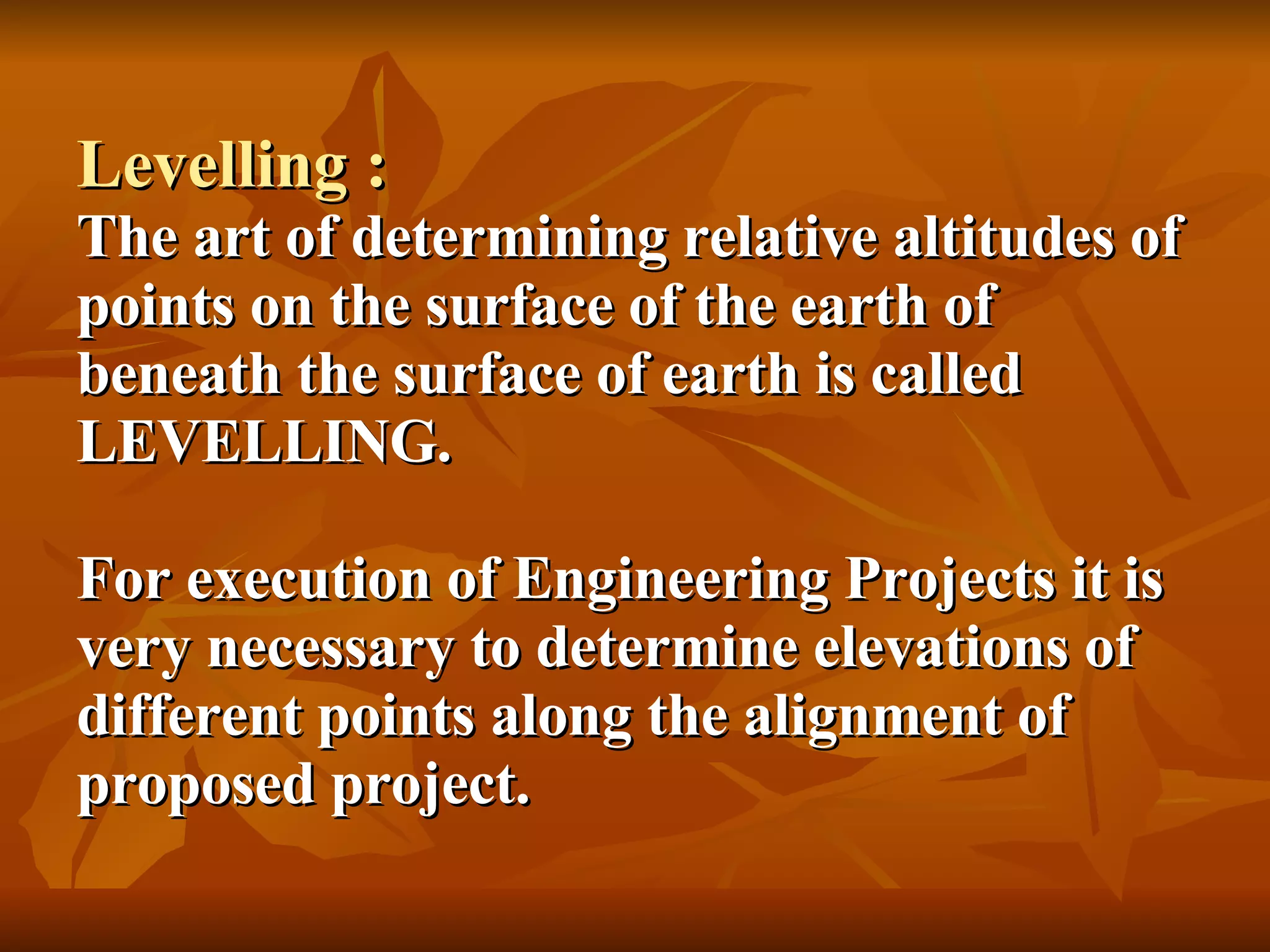
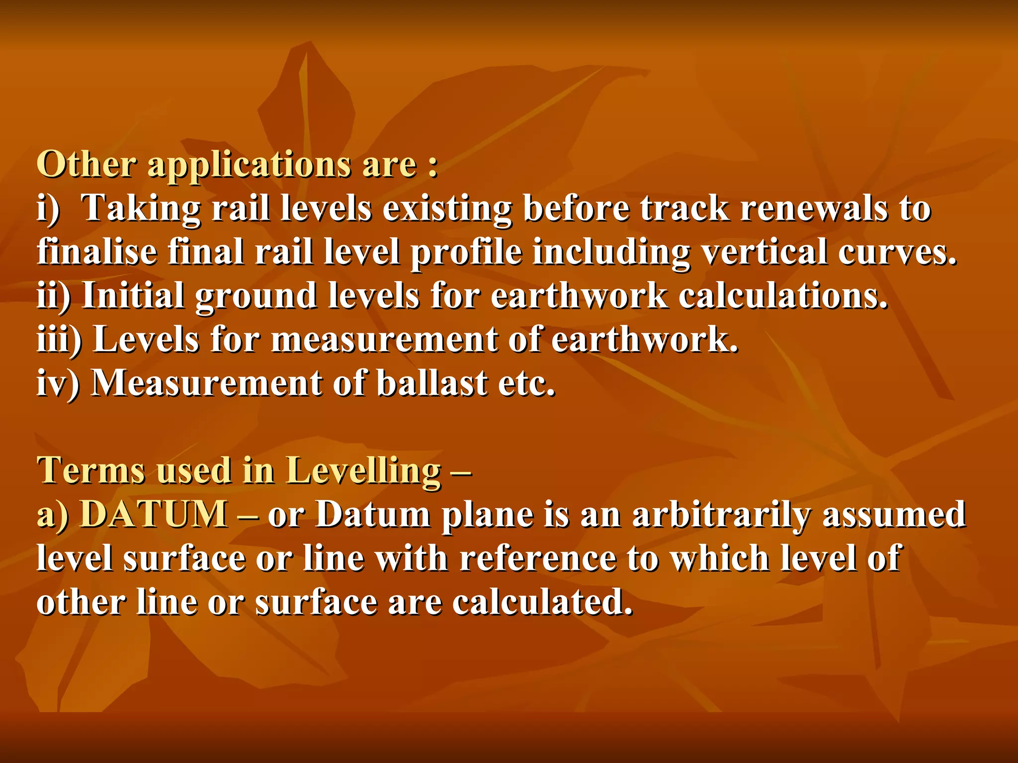
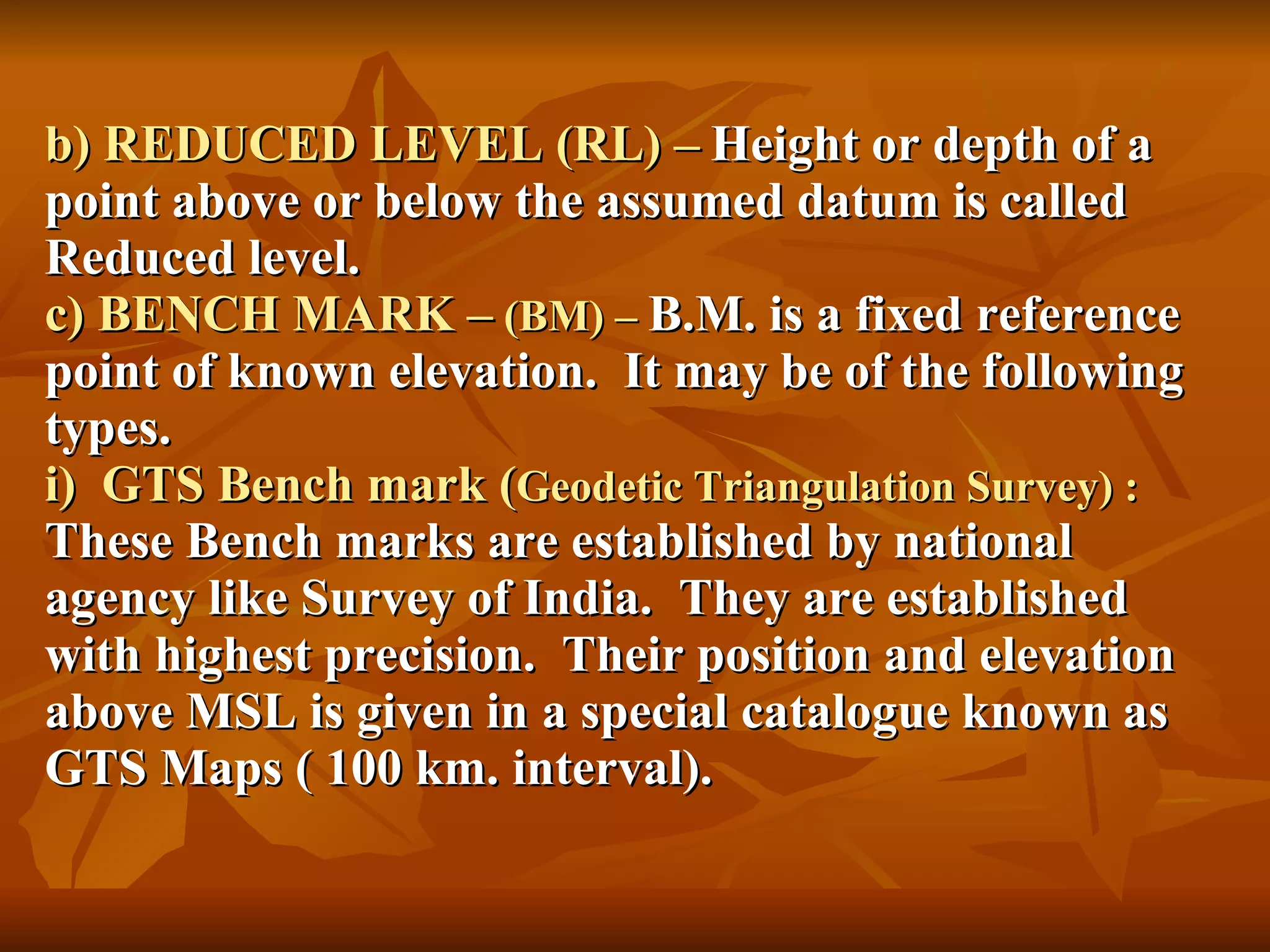
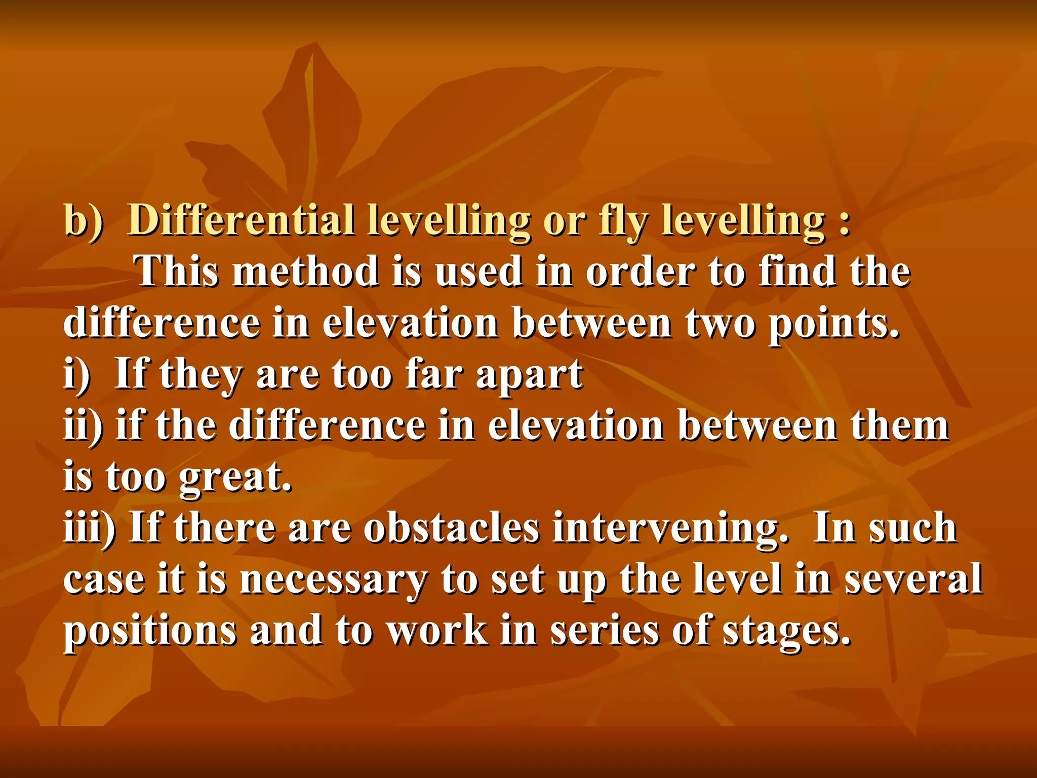
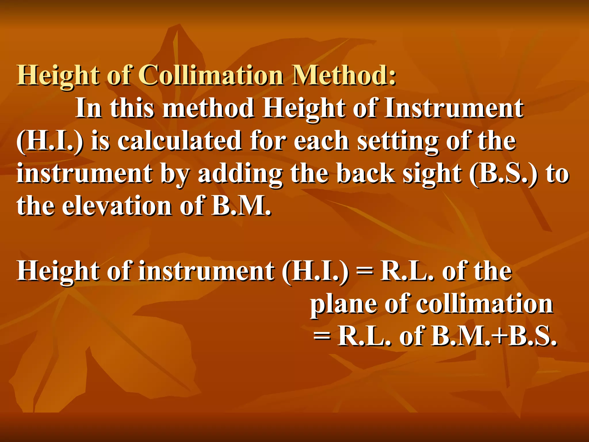
Surveying is used at various stages of a construction project from conceptual planning to maintenance. It involves measuring positions and elevations to determine spatial relationships and enable engineering design and construction. Common surveying methods include chain, compass, theodolite, plane table, tachometric, aerial photographic, and remote sensing surveys. Levelling specifically refers to determining relative elevations and is important for engineering works like establishing rail and road alignments and profiles. Key levelling instruments are dumpy level, tilting level, automatic level, and digital level.
Edm is a surveying instrument used to measure the distance electronically. This Surveying Instrument is used in triangulation to measure the length of Base line because more accuracy is required to measure the length of base line.
A small description about the principle and operation of widely used instrument 'Total Station' in Civil Engineering and Global Positioning System through a technical view...!
Introduction to Surveying LEVELLING PROCEDURESBahzad5
Introduction to Surveying LEVELLING PROCEDURES
Review of levelling
• In this lecture we will cover :
Equipment and procedures
Purposes of levelling
Some definitions
Reading a staff
Temporary adjustment of level
Booking and reduction
Methods of booking
Applications
Leveling:-
Leveling defined as an operation for the measurement of the
difference in the elevation between points or for the determination
of the elevation of certain points above some given plane or
surface known as the datum surface , generally is taken as the
mean sea level (M S L)
Leveling
Is a type of surveying which is carried out for finding difference in
heights in engineering projects. Leveling is required for various
purposes such as for
calculation of the depth of cutting and fillings, for setting out
grades for sewerage and pipe lines, etc.
Types of Leveling and Application
I. Direct Methods :
II. Indirect Leveling
1. Simple Levelling .
2. Compound Levelling or Differential Levelling.
3.Flying Levelling.
4-Contours map
5. Longitudinal or profile Levelling.
6. Cross-section Levelling.
7.Reciprocal Levelling.
8-Precise Levelling.
Level instrument
Types of Level Instruments & Parts of level instrument
1. Dumpy Level
2. Tilting Level
3. Automatic Level
4. Electronic Level
5. Hand Level
6-Digital level
-Temporary adjustment of level.
-The procedure is repeated.. till the bubble remains in the center in both the positions.
-Leveling staves
*Types of Staff (Rod).
Reading Staff.
What is Leveling?
Prepared by:
Asst. Prof. Salar K.Hussein
Mr. Kamal Y.Abdullah
Asst.Lecturer. Dilveen H. Omar
Erbil Polytechnic University
Technical Engineering College
Civil Engineering Department
UiPath Test Automation using UiPath Test Suite series, part 4DianaGray10
Welcome to UiPath Test Automation using UiPath Test Suite series part 4. In this session, we will cover Test Manager overview along with SAP heatmap.
The UiPath Test Manager overview with SAP heatmap webinar offers a concise yet comprehensive exploration of the role of a Test Manager within SAP environments, coupled with the utilization of heatmaps for effective testing strategies.
Participants will gain insights into the responsibilities, challenges, and best practices associated with test management in SAP projects. Additionally, the webinar delves into the significance of heatmaps as a visual aid for identifying testing priorities, areas of risk, and resource allocation within SAP landscapes. Through this session, attendees can expect to enhance their understanding of test management principles while learning practical approaches to optimize testing processes in SAP environments using heatmap visualization techniques
What will you get from this session?
1. Insights into SAP testing best practices
2. Heatmap utilization for testing
3. Optimization of testing processes
4. Demo
Topics covered:
Execution from the test manager
Orchestrator execution result
Defect reporting
SAP heatmap example with demo
Speaker:
Deepak Rai, Automation Practice Lead, Boundaryless Group and UiPath MVP
Search and Society: Reimagining Information Access for Radical FuturesBhaskar Mitra
The field of Information retrieval (IR) is currently undergoing a transformative shift, at least partly due to the emerging applications of generative AI to information access. In this talk, we will deliberate on the sociotechnical implications of generative AI for information access. We will argue that there is both a critical necessity and an exciting opportunity for the IR community to re-center our research agendas on societal needs while dismantling the artificial separation between the work on fairness, accountability, transparency, and ethics in IR and the rest of IR research. Instead of adopting a reactionary strategy of trying to mitigate potential social harms from emerging technologies, the community should aim to proactively set the research agenda for the kinds of systems we should build inspired by diverse explicitly stated sociotechnical imaginaries. The sociotechnical imaginaries that underpin the design and development of information access technologies needs to be explicitly articulated, and we need to develop theories of change in context of these diverse perspectives. Our guiding future imaginaries must be informed by other academic fields, such as democratic theory and critical theory, and should be co-developed with social science scholars, legal scholars, civil rights and social justice activists, and artists, among others.
JMeter webinar - integration with InfluxDB and GrafanaRTTS
Watch this recorded webinar about real-time monitoring of application performance. See how to integrate Apache JMeter, the open-source leader in performance testing, with InfluxDB, the open-source time-series database, and Grafana, the open-source analytics and visualization application.
In this webinar, we will review the benefits of leveraging InfluxDB and Grafana when executing load tests and demonstrate how these tools are used to visualize performance metrics.
Length: 30 minutes
Session Overview
-------------------------------------------
During this webinar, we will cover the following topics while demonstrating the integrations of JMeter, InfluxDB and Grafana:
- What out-of-the-box solutions are available for real-time monitoring JMeter tests?
- What are the benefits of integrating InfluxDB and Grafana into the load testing stack?
- Which features are provided by Grafana?
- Demonstration of InfluxDB and Grafana using a practice web application
To view the webinar recording, go to:
https://www.rttsweb.com/jmeter-integration-webinar
Essentials of Automations: Optimizing FME Workflows with ParametersSafe Software
Are you looking to streamline your workflows and boost your projects’ efficiency? Do you find yourself searching for ways to add flexibility and control over your FME workflows? If so, you’re in the right place.
Join us for an insightful dive into the world of FME parameters, a critical element in optimizing workflow efficiency. This webinar marks the beginning of our three-part “Essentials of Automation” series. This first webinar is designed to equip you with the knowledge and skills to utilize parameters effectively: enhancing the flexibility, maintainability, and user control of your FME projects.
Here’s what you’ll gain:
- Essentials of FME Parameters: Understand the pivotal role of parameters, including Reader/Writer, Transformer, User, and FME Flow categories. Discover how they are the key to unlocking automation and optimization within your workflows.
- Practical Applications in FME Form: Delve into key user parameter types including choice, connections, and file URLs. Allow users to control how a workflow runs, making your workflows more reusable. Learn to import values and deliver the best user experience for your workflows while enhancing accuracy.
- Optimization Strategies in FME Flow: Explore the creation and strategic deployment of parameters in FME Flow, including the use of deployment and geometry parameters, to maximize workflow efficiency.
- Pro Tips for Success: Gain insights on parameterizing connections and leveraging new features like Conditional Visibility for clarity and simplicity.
We’ll wrap up with a glimpse into future webinars, followed by a Q&A session to address your specific questions surrounding this topic.
Don’t miss this opportunity to elevate your FME expertise and drive your projects to new heights of efficiency.
UiPath Test Automation using UiPath Test Suite series, part 3DianaGray10
Welcome to UiPath Test Automation using UiPath Test Suite series part 3. In this session, we will cover desktop automation along with UI automation.
Topics covered:
UI automation Introduction,
UI automation Sample
Desktop automation flow
Pradeep Chinnala, Senior Consultant Automation Developer @WonderBotz and UiPath MVP
Deepak Rai, Automation Practice Lead, Boundaryless Group and UiPath MVP
Software Delivery At the Speed of AI: Inflectra Invests In AI-Powered QualityInflectra
In this insightful webinar, Inflectra explores how artificial intelligence (AI) is transforming software development and testing. Discover how AI-powered tools are revolutionizing every stage of the software development lifecycle (SDLC), from design and prototyping to testing, deployment, and monitoring.
Learn about:
• The Future of Testing: How AI is shifting testing towards verification, analysis, and higher-level skills, while reducing repetitive tasks.
• Test Automation: How AI-powered test case generation, optimization, and self-healing tests are making testing more efficient and effective.
• Visual Testing: Explore the emerging capabilities of AI in visual testing and how it's set to revolutionize UI verification.
• Inflectra's AI Solutions: See demonstrations of Inflectra's cutting-edge AI tools like the ChatGPT plugin and Azure Open AI platform, designed to streamline your testing process.
Whether you're a developer, tester, or QA professional, this webinar will give you valuable insights into how AI is shaping the future of software delivery.
GraphRAG is All You need? LLM & Knowledge GraphGuy Korland
Guy Korland, CEO and Co-founder of FalkorDB, will review two articles on the integration of language models with knowledge graphs.
1. Unifying Large Language Models and Knowledge Graphs: A Roadmap.
https://arxiv.org/abs/2306.08302
2. Microsoft Research's GraphRAG paper and a review paper on various uses of knowledge graphs:
https://www.microsoft.com/en-us/research/blog/graphrag-unlocking-llm-discovery-on-narrative-private-data/
Smart TV Buyer Insights Survey 2024 by 91mobiles.pdf91mobiles
91mobiles recently conducted a Smart TV Buyer Insights Survey in which we asked over 3,000 respondents about the TV they own, aspects they look at on a new TV, and their TV buying preferences.
Kubernetes & AI - Beauty and the Beast !?! @KCD Istanbul 2024Tobias Schneck
As AI technology is pushing into IT I was wondering myself, as an “infrastructure container kubernetes guy”, how get this fancy AI technology get managed from an infrastructure operational view? Is it possible to apply our lovely cloud native principals as well? What benefit’s both technologies could bring to each other?
Let me take this questions and provide you a short journey through existing deployment models and use cases for AI software. On practical examples, we discuss what cloud/on-premise strategy we may need for applying it to our own infrastructure to get it to work from an enterprise perspective. I want to give an overview about infrastructure requirements and technologies, what could be beneficial or limiting your AI use cases in an enterprise environment. An interactive Demo will give you some insides, what approaches I got already working for real.
Connector Corner: Automate dynamic content and events by pushing a buttonDianaGray10
Here is something new! In our next Connector Corner webinar, we will demonstrate how you can use a single workflow to:
Create a campaign using Mailchimp with merge tags/fields
Send an interactive Slack channel message (using buttons)
Have the message received by managers and peers along with a test email for review
But there’s more:
In a second workflow supporting the same use case, you’ll see:
Your campaign sent to target colleagues for approval
If the “Approve” button is clicked, a Jira/Zendesk ticket is created for the marketing design team
But—if the “Reject” button is pushed, colleagues will be alerted via Slack message
Join us to learn more about this new, human-in-the-loop capability, brought to you by Integration Service connectors.
And...
Speakers:
Akshay Agnihotri, Product Manager
Charlie Greenberg, Host
Neuro-symbolic is not enough, we need neuro-*semantic*Frank van Harmelen
Neuro-symbolic (NeSy) AI is on the rise. However, simply machine learning on just any symbolic structure is not sufficient to really harvest the gains of NeSy. These will only be gained when the symbolic structures have an actual semantics. I give an operational definition of semantics as “predictable inference”.
All of this illustrated with link prediction over knowledge graphs, but the argument is general.
LF Energy Webinar: Electrical Grid Modelling and Simulation Through PowSyBl -...DanBrown980551
Do you want to learn how to model and simulate an electrical network from scratch in under an hour?
Then welcome to this PowSyBl workshop, hosted by Rte, the French Transmission System Operator (TSO)!
During the webinar, you will discover the PowSyBl ecosystem as well as handle and study an electrical network through an interactive Python notebook.
PowSyBl is an open source project hosted by LF Energy, which offers a comprehensive set of features for electrical grid modelling and simulation. Among other advanced features, PowSyBl provides:
- A fully editable and extendable library for grid component modelling;
- Visualization tools to display your network;
- Grid simulation tools, such as power flows, security analyses (with or without remedial actions) and sensitivity analyses;
The framework is mostly written in Java, with a Python binding so that Python developers can access PowSyBl functionalities as well.
What you will learn during the webinar:
- For beginners: discover PowSyBl's functionalities through a quick general presentation and the notebook, without needing any expert coding skills;
- For advanced developers: master the skills to efficiently apply PowSyBl functionalities to your real-world scenarios.
"Impact of front-end architecture on development cost", Viktor TurskyiFwdays
I have heard many times that architecture is not important for the front-end. Also, many times I have seen how developers implement features on the front-end just following the standard rules for a framework and think that this is enough to successfully launch the project, and then the project fails. How to prevent this and what approach to choose? I have launched dozens of complex projects and during the talk we will analyze which approaches have worked for me and which have not.
FIDO Alliance Osaka Seminar: Passkeys and the Road Ahead.pdf
Basics Of Surveying
1. SURVEYING Preamble Surveying is involved in a project from conceptual stage to construction and afterwards in maintenance also. Depending on the stage at which surveying is carried out it can be called. i) Pre construction survey Feasibility survey (RECT, PECT) ii) Construction survey To maintain alignment and Geometry control during construction. (FLS and other ) iii) Post construction Maintenance survey
2. Definition : Operation of making such measurements that the relative position of various features, natural or Artificial on the surface of the earth can be exhibited in their correct Horizontal and vertical relationship. Normally determining position in Horizontal plane is called surveying. Determining relative heights or depth is called levelling.
3. Purpose : The main object of surveying is the preparation of maps or plans which are the basis in planning and design of engineering project such as route location of railway line, roads and water supply scheme. Basic Principles in Surveying : Ruling principle of survey is : i) “ to work from whole to part”. For surveying Establish control points with high precision by use of Triangulation and precise levelling. Area is further divided into triangle, which are surveyed with less accuracy. ii) to fix the position of new stations by atleast two independent processes – By linear and Angular
4. Classification of Surveys : Surveying is divided into two main categories- i) Geodetic Survey ii) Plane survey i) Geodetic Survey :- When survey extends over a large areas more than 200 sq. km. and degree of accuracy is also great. The curvature of earth is also taken into account. Geodetic survey is used to provide control points to which small surveys can be connected. ii) Plane Survey :- For small projects covering Area less than 200 sq.km. Earth curvature is not counted for in distances. Earth surface is considered as plane. (Angular error of 1” in 200 sq. km. area by assuming plane).
5.
6. Levelling : The art of determining relative altitudes of points on the surface of the earth of beneath the surface of earth is called LEVELLING. For execution of Engineering Projects it is very necessary to determine elevations of different points along the alignment of proposed project.
7. Other applications are : i) Taking rail levels existing before track renewals to finalise final rail level profile including vertical curves. ii) Initial ground levels for earthwork calculations. iii) Levels for measurement of earthwork. iv) Measurement of ballast etc. Terms used in Levelling – a) DATUM – or Datum plane is an arbitrarily assumed level surface or line with reference to which level of other line or surface are calculated.
8. b) REDUCED LEVEL (RL) – Height or depth of a point above or below the assumed datum is called Reduced level. c) BENCH MARK – (BM) – B.M. is a fixed reference point of known elevation. It may be of the following types. i) GTS Bench mark ( Geodetic Triangulation Survey) : These Bench marks are established by national agency like Survey of India. They are established with highest precision. Their position and elevation above MSL is given in a special catalogue known as GTS Maps ( 100 km. interval).
9. ii) Permanent Bench Mark : They are fixed points of reference establish with reference to GTS Bench mark (10 km. interval). iii) Arbitrary Bench mark : These are reference points whose elevations are arbitrarily assumed. In most of Engineering projects, the difference in elevation is more important than their reduced levels with reference to MSL as given in a special catalogue known as GTS Maps ( 100 Km. interval).
10.
11.
12. k) Change Point (CP) : The point on which both the foresight and back sight are taken during the operation of levelling is called change point. l) Intermediate Sight (IS) : The foresight taken on a levelling staff held at a point between two turning points, to determine the elevation of that point, is known as intermediate sight.
13. It may be noted that for one setting of a level, there will be only one back sight and one foresight but there can be any number of intermediate sights. Type of Levelling Equipments: i) Dumpy level ii) Tilting level iii) Automatic level iv) Digital Auto level Dumpy level : It is simple compact and stable. The telescope is rigidly fixed to its support therefore cannot be rotated about its longitudinal axis. A long bubble tube is attached to the top of telescope. Dumpy literally means short and thick.
14. Tilting level : It consists of a telescope attached with a level tube which can be tilted within few degrees in vertical plane by a tilting screw. The main peculiarity of this level is that the vertical axis need not be truly vertical, since the line of collimation is not perpendicular to it. The line of collimation, is, however, made horizontal for each pointing of telescope by means of tilting screw. It is mainly designed for precise levelling work.
15. The Automatic level : Also termed as self aligning level. The fundamental difference between automatic and the classic spirit level is that in the former the line of sight is no longer levelled manually using a tubular spirit level, but is levelled automatically within a certain tilt range. This is achieved by compensator in the telescope.
16. Advantage of automatic level i) Much simpler to use ii) High precision – Mean elevation error on staff graduated to 5mm division varies between +0.5 to 0.8 mm per km of forward and backward levelling. iii) High speed : For fly levelling the progress achieved by various level-wise compared.
17. Type of level D(m) 20m 40 60 80 100 120 Automatic level speed 1.2 2 2.4 2.5 2.6 2.7 S(Km/hr) Tilting level speed 0.6 1.1 1.5 1.7 1.8 1.9 S(Km/hr) S = Speed of levelling in km/hr. D = Sighting distance in meter. The speed of Dumpy level is about 25% lower than tilting level. iv) Freedom from errors – Accuracy is increased by an errect telescope image. v) Range of application – level can be used on medium and large sized projects and setting bench marks.
18. Basic components of level : 1. Telescope – to provide a line of sight 2. Level Tube – to make line of sight horizontal 3. Levelling head – to bring the bubble of tube level at the centre of its run. 4. Tripod – to support the above three parts of the level. 1. TELESCOPE : Telescope is an optical instrument used for magnifying and viewing the images of distant objects. It consists of two lenses. The lens fitted near the eye is called the eye piece and the other fitted at the end near to the object is called the objective lens.
19. The objective provides a real inverted image infront of the eye piece at a distance lesser than its focal distance. Two essential conditions are involved. : i) The real image of the object, must be formed. Ii) the plane of image must coincide with that of cross hairs. Focusing of Telescope : The operation of obtaining a clear image of the object in the plane of cross hairs is known as focusing.
20. 1. Diaphram : A frame carrying cross hairs usually made of either silk thread or platinum wire and placed at the plane at which vertical image of the object is formed by the objective. Vertical hair of the diaphram enables the surveyor to check the verticality of levelling staff whereas horizontal hairs are used to read the staff graduations. 2.Level Tube : Also known as Bubble Tube consists of a glass tube placed in a brass tube which is sealed with plaster of paris. The whole of the interior surface or the upper half is accurately ground so that its longitudinal section, is an arc of a circle. Level tube is filled with either or alcohol, the remaining space is occupied by an air bubble. The centre of air bubble always rest at the highest point of the tube.
21. Outer surface of the bubble tube is graduated in both the directions from the centre. The line tangential to the circular are at its highest point i.e. the middle of tube is called the axis of bubble tube. When the bubble is central the axis of bubble becomes Horizontal. The level tube is attached on the top of Telescope by means of capstan headed nuts.
22.
23. Adjustment of level : i) Temporarily Adjustments – adjustments which are made for every setting of a level. ii) Permanent adjustments- required if some error is there in instrument. i) Temporary Adjustments : includes a) setting up the level b) levelling up c) elimination of parallax a) Setting up the level : This operation includes fixing the instrument on the tripod and also approximate levelling by leg adjustment.
24. b) Levelling up : Accurate levelling is done with the help of foot screws and by using plate levels. The object of levelling up the instrument is to make its vertical axis truly vertical. c) Elimination of parallax : If the image formed by the objective does not lie in the plane of the cross hairs, there will be a shift in the image due to shift of the eye. Such displacement of image is termed as parallax. Parallax is removed in two stages. 1) Focusing the eye for distinct vision of cross hairs. 2) Focusing the objective so that image is formed in the plane of cross hairs.
25. Principles of levelling : a) Simple levelling : The operation of levelling for determining the difference in elevation, if not too great between two points visible from single position of the level is known as simple levelling. PROCEDURE : Following steps are involved.
26.
27. b) Differential levelling or fly levelling : This method is used in order to find the difference in elevation between two points. i) If they are too far apart ii) if the difference in elevation between them is too great. iii) If there are obstacles intervening. In such case it is necessary to set up the level in several positions and to work in series of stages.
28. The difference of level of the points A&B is equal to the algebraic sum of these difference between the sum of back sights and sum of the fore sights i.e. Σ BS - Σ FS Booking and reduction of the levels may be done by following 2 methods. i) Rise and fall method ii) Height of collimation method
29. RISE AND FALL METHOD – In this method, the difference of level between two consecutive points for each setting of the instrument is obtained by comparing their staff readings. The difference between their staff readings indicates a rise if back sight is more than foresight and a fall if it is less than foresight. The Rise and Fall worked out for all the points given the vertical distances of each point relative to the proceeding one. If the RL of the Back staff point is known, then RL of the following staff point may be obtained by adding its rise or substracting fall from the RL of preceding point.
30. Height of Collimation Method: In this method Height of Instrument (H.I.) is calculated for each setting of the instrument by adding the back sight (B.S.) to the elevation of B.M. Height of instrument (H.I.) = R.L. of the plane of collimation = R.L. of B.M.+B.S.
31. RL of a point = H.I. – FS Or = H.I. – IS - After every back sight, there may be many intermediate sights but there must be only one foresight. - The B.S. & F.S. forms the two ends of one stage in levelling. - Levelling should always commence from a permanent B.M. and end on a permanent B.M.
32.
33. THEODOLITE - An instrument used for measuring horizontal and vertical angles accurately is known as theodolite. Uses of Theodolite i) Measurement of Horizontal and vertical angles. Ii) Setting out lines and angles iii) Optical distance measurement iv) Plumbing tall building v) Setting out of Railway curves vi) Locating the position of piers for Bridge etc. vii) Geographical position fixing from observation of sun and stars. viii) Alignment control in tunnel construction.
34. Types of Theodolite : Transit theodolites are categorised into 3 types : 1. Vernier theodolite 2. Optical Reading Theodolite 3. Digital Theodolite/Electronic Theodolite Basically Transit Theodolite are those in which the telescope can revolve through a complete revolution about its Horizontal axis in vertical plane.
35. Components of Transit theodolite – Transit theodolite consists of the following parts : 1. Levelling Head 2. Lower Plate or Scale Plate 3. Upper Plate or Vernier Plate 4. The standard or A Frame 5. T-Frame or Index Bar. 6. Plate Levels 7. Telescope
36.
37.
38.
39. 4 . Plate Levels - Upper plates carries two plate levels placed at right angles to each other. One of the plate bubble is kept parallel to the trunion axis. Plate levels can be centred with the help of foot screws. 5. Telescope – Telescope is supported on the pivots of the trunion axis which affords its movement in the vertical plane. IMPORTANT DEFINITIONS – I) Line of Collimation - the line which passes through the Intersection of the cross hairs of the eye piece and optical centre of the objective and its continuation is called as line of collimation. This is also known as line of sight.
40.
41. iv) Face left observation – When vertical circle is on the left of the telescope at the time of observation, the observations are called face left observation. v) Face right observation – When vertical circle is on the right of the telescope at the time of observation. TEMPORARY ADJUSTMENT OF THEODOLITE 1) Setting up the Theodolite over the station 2) Levelling up the theodolite 3) Elimination of the parallax
42.
43. ii) Bring the bubble to the centre of its run by turning both foot screws simultaneously in opposite directions either inwards or outwards. The movement of the left thumb indicates the direction of movement of bubble. iii) Turn the instrument through 180 0 in azimuth. iv) Note the position of the bubble. If it occupies a different position, move it by means of the same two foot screws to the approx. mean of the two positions.v) Turn the theodolite through 90 in azimuth so that the plate level becomes perpendicular to the previous position. vi) With the help of third floor screw, move the bubble to the approx. mean position already indicated.
44. vii) Repeat the process until the bubble, retains the same position for every setting of the instrument. 3. Elimination of Parallax : Elimination of parallax may be done by focusing the eye piece for distinct vision of cross hairs and focusing the objective to bring the image of the object in the plane of cross hairs. Measurement of Horizontal Angle Procedure : to measure a Horizontal Angle ABC between BA & BC the following procedure is followed.
45.
46. 4. Unclamp the upper plate and swing the telescope in clockwise direction until point C is brought in the field of view. Tighten the upper clamp and bisect the mark of C accurately, using the upper clamp tangent screw. 5. Read both the verniers and take the mean of readings. The difference of the means of the reading to C to A is the required angle ABC.
47. 6. Change the face of the instrument and repeat the show procedure, the measure of the angle is again obtained by taking the difference of the means of the readings to C&A on face right. 7. The mean of the two measures of the angle ABC on two faces is the required value of the angle ABC.