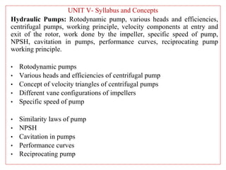
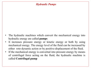
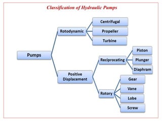
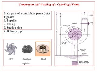
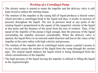
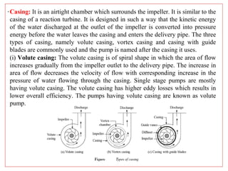
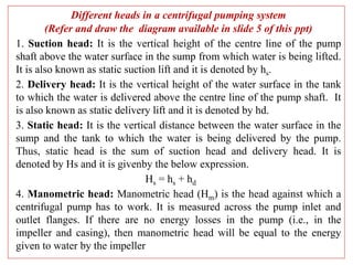
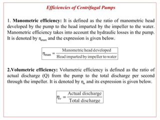
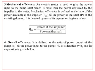
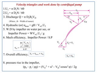
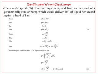
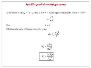
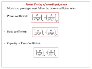
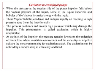
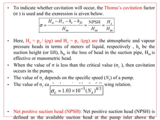
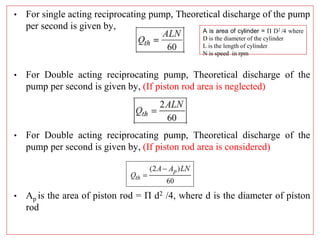
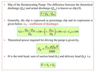
SlideShare a Scribd company logo
Fluid Mechanics
and
Fluid Machines
(A3MET305)
UNIT V- Syllabus and Concepts
Hydraulic Pumps: Rotodynamic pump, various heads and efficiencies,
centrifugal pumps, working principle, velocity components at entry and
exit of the rotor, work done by the impeller, specific speed of pump,
NPSH, cavitation in pumps, performance curves, reciprocating pump
working principle.
• Rotodynamic pumps
• Various heads and efficiencies of centrifugal pump
• Concept of velocity triangles of centrifugal pumps
• Different vane configurations of impellers
• Specific speed of pump
• Similarity laws of pump
• NPSH
• Cavitation in pumps
• Performance curves
• Reciprocating pump
Hydraulic Pumps
• The hydraulic machines which convert the mechanical energy into
hydraulic energy are called pumps
• It increases pressure energy or kinetic energy or both by using
mechanical energy. The energy level of the fluid can be increased by
either roto dynamic action or by positive displacement of the fluid.
• If the mechanical energy is converted into pressure energy by means
of centrifugal force acting on the fluid, the hydraulic machine is
called Centrifugal pump
Classification of Hydraulic Pumps
Components and Working of a Centrifugal Pump
Main parts of a centrifugal pump (refer
Fig) are:
1. Impeller
2. Casing
3. Suction pipe
4. Delivery pipe
Working of a Centrifugal Pump
• The electric motor is started to rotate the impeller and the delivery valve is still
kept closed to reduce the starting torque.
• The rotation of the impeller in the casing full of liquid produces a forced vortex
which provides a centrifugal head to the liquid and thus, it results in increase of
pressure throughout the liquid. The rise in pressure head at any point of the
rotating liquid is proportional to the square of the tangential velocity of the liquid
at that point and the distance of the point from the axis of rotation. Thus, if the
speed of the impeller of the pump is high enough, then the pressure of the liquid
surrounding the impeller increases considerably. When the delivery valve is
opened, the liquid flows in an outward radial direction and leaves the vanes of the
impeller at the outer radius with high velocity and pressure.
• The rotation of the impeller due to centrifugal action causes a partial vacuum at
its eye which causes the suction of the liquid from the sump through the suction
pipe. The sucked liquid replaces the liquid which is being discharged from the
whole circumference of the impeller.
• The high pressure of the liquid leaving the impeller is utilized in lifting the liquid
to the required height.
.Casing: It is an airtight chamber which surrounds the impeller. It is similar to the
casing of a reaction turbine. It is designed in such a way that the kinetic energy
of the water discharged at the outlet of the impeller is converted into pressure
energy before the water leaves the casing and enters the delivery pipe. The three
types of casing, namely volute casing, vortex casing and casing with guide
blades are commonly used and the pump is named after the casing it uses.
(i) Volute casing: The volute casing is of spiral shape in which the area of flow
increases gradually from the impeller outlet to the delivery pipe. The increase in
area of flow decreases the velocity of flow with corresponding increase in the
pressure of water flowing through the casing. Single stage pumps are mostly
having volute casing. The volute casing has higher eddy losses which results in
lower overall efficiency. The pumps having volute casing are known as volute
pump.
Different heads in a centrifugal pumping system
(Refer and draw the diagram available in slide 5 of this ppt)
1. Suction head: It is the vertical height of the centre line of the pump
shaft above the water surface in the sump from which water is being lifted.
It is also known as static suction lift and it is denoted by hs.
2. Delivery head: It is the vertical height of the water surface in the tank
to which the water is delivered above the centre line of the pump shaft. It
is also known as static delivery lift and it is denoted by hd.
3. Static head: It is the vertical distance between the water surface in the
sump and the tank to which the water is being delivered by the pump.
Thus, static head is the sum of suction head and delivery head. It is
denoted by Hs and it is givenby the below expression.
Hs = hs + hd
4. Manometric head: Manometric head (Hm) is the head against which a
centrifugal pump has to work. It is measured across the pump inlet and
outlet flanges. If there are no energy losses in the pump (i.e., in the
impeller and casing), then manometric head will be equal to the energy
given to water by the impeller
Efficiencies of Centrifugal Pumps
1. Manometric efficiency: It is defined as the ratio of manometric head
developed by the pump to the head imparted by the impeller to the water.
Manometric efficiency takes into account the hydraulic losses in the pump.
It is denoted by ɳman and the expression is given below.
2.Volumetric efficiency: Volumetric efficiency is defined as the ratio of
actual discharge (Q) from the pump to the total discharge per second
through the impeller. It is denoted by ɳv and its expression is given below.
3.Mechanical efficiency: An electric motor is used to give the power
input to the pump shaft which is more than the power delivered by the
impeller to the water. Mechanical efficiency is defined as the ratio of the
power available at the impeller (Pim) to the power at the shaft (P) of the
centrifugal pump. It is denoted by m and its expression is given below.
4. Overall efficiency: It is defined as the ratio of power output of the
pump (Po) to the power input to the pump (P). It is denoted by ɳo and its
expression is given below.
Velocity triangles and work done by centrifugal pump
1.U1 = π D1N / 60
2.U2 = π D2N / 60
3. Discharge Q = π D2B2Vf2
(Where , B – Width of runner)
4. Hydraulic (or) ɳman = gH / Vw2 U2
5. W.D by impeller on water per sec, or
Impeller Power = WVw2 U2 / g
6. Mech efficiency, Impeller Power / S.P
7. Overall efficiency,
8. pressure rise in the impeller,
(p0 – pi / ρg) = (Vf1
2 + u2 – Vf2
2 cosec2 φ) / 2g
Vf1 = Vf2
Specific speed of centrifugal pumps
•The specific speed (Ns) of a centrifugal pump is defined as the speed of a
geometrically similar pump which would deliver 1m3 of liquid per second
against a head of 1 m.
Specific speed of centrifugal pumps
Model Testing of centrifugal pumps
⮚ Model and prototype must follow the below coefficient rules:
• Power coefficient:
• Head coefficient:
• Capacity or Flow Coefficient:
Cavitation in centrifugal pumps
• When the pressure at the suction side of the pump impeller falls below
the Vapour pressure of the liquid, some of the liquid vaporizes and
bubbles of the Vapour is carried along with the liquid.
• These Vapour bubbles condense and collapse rapidly on reaching to high
pressure zone (near the impeller exit).
• This process continues and creates high pressure which may damage the
impeller. This phenomenon is called cavitation which is highly
undesirable.
• At the inlet of the impeller, the pressure remains lowest on the underside
of vanes from where cavitation commences and the vanes tips at impeller
exit are the most common site for cavitation attack. The cavitation can be
noticed by a sudden drop in efficiency and head.
• To indicate whether cavitation will occur, the Thoma’s cavitation factor
(σ ) is used and the expression is given below.
• Here, Ha = pa / (ρg) and Hv = pv /(ρg) are the atmospheric and vapour
pressure heads in terms of meters of liquid, respectively , hs be the
suction height (or lift), hfs is the loss of head in the suction pipe, Hm is
effective or manometric head.
• When the value of σ is less than the critical value (σc ), then cavitation
occurs in the pumps.
• The value of σc depends on the specific speed (Ns) of a pump.
• The value of σc can be determined by the following relation.
• Net positive suction head (NPSH): Net positive suction head (NPSH) is
defined as the available suction head at the pump inlet above the
 The cavitation in pumps can be avoided by the following factors
1. By reducing the suction lift that increases the value of which ensures
sufficient availability of NPSH.
2. By reducing the velocity in the suction pipe.
3. By avoiding the bends.
4. By reducing hfs in suction pipe.
5. By selecting the pump of lower specific speed.
 Cavitation is undesirable due to the following harmful effects
1. A large number of Vapour bubbles formed suddenly collapse in a high
pressure region which causes the rush of surrounding liquid and results in
shock, noise and vibration. This phenomenon is called water hammer.
2. The continuous water hammering action of collapsing bubbles causes
pitting and erosion of the surface.
3. The water hammer causes fatigue of the metal parts and reduces their
lifetime.
4. Cavitation causes sudden drop in head and efficiency
Performance characteristic curves of centrifugal pumps
• Pump provides maximum efficiency when it operates at designed
values of speed, discharge and head. In actual practice, a pump has to
operate at different conditions than the designed ones under which the
behavior of the pump may be different. In order to predict the behavior
and performance of a pump under varying conditions, various tests are
performed and the results of the tests are plotted in the form of curves.
These curves are known as the characteristic curves of the pump.
• The important characteristic curves of a pump are (i) main
characteristic curves, (ii) operating characteristic curves, (iii) constant
efficiency or Muschel curves, and (iv) constant head and constant
discharge characteristic curves
i) Main Characteristic Curves:
ii) Operating characteristic curves iii) Constant efficiency or Muschel curves
iv) Constant head and constant discharge characteristic curves
Reciprocating Pumps
• The reciprocating pumps are positive displacement pumps in which a certain
volume of liquid is taken in an enclosed volume and then it is forced out against
pressure to the required application.
• The mechanical energy is converted into pressure energy by sucking the liquid
into a cylinder in which a piston is reciprocating which exerts the thrust on the
liquid and increases its pressure energy.
• The reciprocating pumps may be classified into (i) Single acting pump: If the
water (liquid) is in contact with one side of piston.
• (ii) Double acting pump: If the water is in contact with both sides of the piston.
• For single acting reciprocating pump, Theoretical discharge of the pump
per second is given by,
• For Double acting reciprocating pump, Theoretical discharge of the
pump per second is given by, (If piston rod area is neglected)
• For Double acting reciprocating pump, Theoretical discharge of the
pump per second is given by, (If piston rod area is considered)
• Ap is the area of piston rod = Π d2 /4, where d is the diameter of piston
rod
A is area of cylinder = Π D2 /4 where
D is the diameter of the cylinder
L is the length of cylinder
N is speed in rpm
• Slip of the Reciprocating Pump: The difference between the theoretical
discharge (Qth) and actual discharge (Qact) is known as slip (S).
• Generally, the slip is expressed as percentage slip and its expression is
given below. (cd – coefficient of discharge)
• Theoretical power required for driving the pump is given by,
• H is the total head, sum of suction head (hs) and delivery head (hd) i.e.
Important long answer questions (Refer your notes for solutions)
1. Explain the working principle of a centrifugal pump with the help of
a line sketch, naming all the parts.
2. With the help of a neat sketch, explain in brief the functioning of
volute casing of a centrifugal pump
3.What are the different efficiencies of a centrifugal pump? Explain
4.Briefly explain different heads in a centrifugal pumping system
5.A centrifugal pump has an impeller of 80 cm diameter and it delivers
1.144 m3/s against a head of 70 m. The impeller runs at 1000 rpm and
its width at outlet is 8 cm. If hydraulic efficiency is 82%, calculate the
blade angle at outlet .
6. A centrifugal pump delivers water against a net head of 10.0 m at a
design speed of 1000 rpm. The vanes are curved backwards and make
an angle of 30o with the tangent at the outer periphery. The impeller
diameter is 30 cm and has a width of 5 cm at the outlet. Determine the
discharge of the pump if the manometric efficiency is 95%.
7.The external and internal diameters of the impeller of a centrifugal
pump are 0.4 m and 0.2 m, respectively. The centrifugal pump runs at
1200 rpm and its vanes at the exit are set back at an angle of 25°. If a
constant radial flow through the impeller is maintained at 2.5 m/s, then
determine (i) the inlet vane angle, (ii) angle made by absolute velocity
at the outlet and (iii) work done by the impeller per unit weight of
8. The internal and external diameters of a centrifugal pump are 10 cm and
20 cm, respectively. It runs at 2800 rpm and delivers 0.105 m3/s of water.
The widths of impeller at the inlet and outlet are 2 cm and 1 cm,
respectively. The water enters the impeller radially at the inlet and impeller
blade angle at the exit is 45°. Determine the pressure rise in the impeller
by assuming that flow velocity as constant and neglecting losses through
it.
9. Determine the specific speed of a centrifugal pump which delivers water
at the rate of 2 m3/s under a head of 20 m while running at 3500 rpm and
operating at a maximum efficiency of 85%. Also determine the discharge,
head and power input to the pump at the speed of 2500 rpm assuming that
the efficiency remains constant at all the speeds.
10. Define specific speed of a centrifugal pump. Derive an expression for
the same
11.Two geometrically similar pumps run at the same speed of 1200 rpm.
One pump with impeller diameter of 0.4 m delivers water at the rate of
0.03 m3/s against the head of 20 m. Determine the diameter and head
delivered by the other pump if it has to deliver 50% discharge of the first
pump
12. Two homologous pumps A and B are to run at the same speed of 600
rpm. Pump A has an impeller of 50 cm diameter and discharges 0.4 m3/s of
water under a net head of 50 m. Determine the diameter of impeller of
pump B and its net head if it is to discharge 0.3 m3/s
13. Determine the height from water surface a centrifugal pump should be
installed to avoid cavitation when atmospheric pressure (abs) is 101.325
kPa, vapour pressure is 2.5 kPa (abs), the inlet and other losses in suction
pipe are 1.5 m, effective head of the pump is 50 m and cavitation factor is
0.115.
14. The following particulars are given for a centrifugal pump, such as
discharge = 0.15 m3/s of water, manometric head = 35 m, speed of the
pump = 1150 rpm, atmospheric pressure (abs) = 1.01325 bar, vapour
pressure at the temperature of water pumped = 3.5 kPa (abs), inlet and
other losses in suction pipe = 0.25 m of water. Determine minimum NPSH
and maximum allowable height of the pump from the free surface of water
in the pump.
15. Define cavitation. What are the effects of cavitation? Give the necessary
precautions against cavitation
16. Describe cavitation phenomenon in centrifugal pump
17. Write a note on the main performance curves of centrifugal pump
18. Explain the properties for a centrifugal pump, such as (i) main
characteristics curves, (ii) operating characteristics curves and (iii)
Muschel curves
19. A single acting reciprocating pump delivers 9 litres per second of water
against a suction head of 4 m and a delivery head of 16 m while running at
a speed of 60 rpm. The diameter and stroke of the piston are 200 mm and
300 mm, respectively. Determine (i) the theoretical discharge, (ii)
coefficient of discharge, (iii) slip, (iv) percentage slip and (v) power
required to drive the pump.
20. A double acting reciprocating pump operating at 55 rpm has a piston
diameter of 0.2 m and piston rod of diameter 40 mm which is on one side
only. The stroke of the piston is 0.3 m. The suction and delivery heads are
5 m and 20 m, respectively. Determine (i) the theoretical discharge and (ii)
power required to drive the pump.
13. Sol:)
14. Sol:)
19. Sol:)
20. Sol:)

More Related Content

What's hot

Steam turbine and its types
Steam turbine and its typesSteam turbine and its types
STEAM NOZZLE AND STEAM TURBINE
STEAM NOZZLE AND STEAM TURBINESTEAM NOZZLE AND STEAM TURBINE
STEAM NOZZLE AND STEAM TURBINE
DHAMMADIP KAMBLE
 
pumps and centrifugal pump and their classifications
pumps and centrifugal pump and their classificationspumps and centrifugal pump and their classifications
pumps and centrifugal pump and their classifications
Talha Hussain
 
Basics of Centrifugal Pump
Basics of Centrifugal PumpBasics of Centrifugal Pump
Basics of Centrifugal Pump
Vikram Sharma
 
Pump, its types and applications presentation
Pump, its types and applications presentationPump, its types and applications presentation
Pump, its types and applications presentation
ziaul islam
 
Chapter 3 centrifugal comp
Chapter 3 centrifugal compChapter 3 centrifugal comp
Chapter 3 centrifugal comp
Novak Djokovich
 
Priming of Centrifugal Pump
Priming of Centrifugal PumpPriming of Centrifugal Pump
Priming of Centrifugal Pump
sajan gohel
 
Pump
PumpPump
Centrifugal Pump
Centrifugal PumpCentrifugal Pump
Industrial fan(ID FD Fans)
Industrial fan(ID FD Fans)Industrial fan(ID FD Fans)
Industrial fan(ID FD Fans)
Amaresh Choudhary
 
Specific volume of steam
Specific volume of steamSpecific volume of steam
Specific volume of steam
Digvijaysinh Gohil
 
Governing of the Turbine | Fluid Mechanics
Governing of the Turbine | Fluid MechanicsGoverning of the Turbine | Fluid Mechanics
Governing of the Turbine | Fluid Mechanics
Satish Taji
 
Axial Flow Compressor.
Axial Flow Compressor. Axial Flow Compressor.
Axial Flow Compressor.
Urvesh Prajapati
 
Nozzle
NozzleNozzle
Centrifugal & reciprocating pumps
Centrifugal & reciprocating  pumpsCentrifugal & reciprocating  pumps
Centrifugal & reciprocating pumps
vishalgohel12195
 
Centrifugal compressor
Centrifugal compressor Centrifugal compressor
Centrifugal compressor
Héctor Nguema Ondo
 
Positive displacement machines
Positive displacement machinesPositive displacement machines
Positive displacement machines
swaroop k s
 
Operation of reciprocating pump
Operation of reciprocating pumpOperation of reciprocating pump
Operation of reciprocating pump
vaibhav tailor
 
Testing and performance characteristics of diesel engine
Testing and performance characteristics of diesel engineTesting and performance characteristics of diesel engine
Testing and performance characteristics of diesel engine
arslan liaqat
 

What's hot (20)

Steam turbine and its types
Steam turbine and its typesSteam turbine and its types
Steam turbine and its types
 
STEAM NOZZLE AND STEAM TURBINE
STEAM NOZZLE AND STEAM TURBINESTEAM NOZZLE AND STEAM TURBINE
STEAM NOZZLE AND STEAM TURBINE
 
pumps and centrifugal pump and their classifications
pumps and centrifugal pump and their classificationspumps and centrifugal pump and their classifications
pumps and centrifugal pump and their classifications
 
Basics of Centrifugal Pump
Basics of Centrifugal PumpBasics of Centrifugal Pump
Basics of Centrifugal Pump
 
Pump, its types and applications presentation
Pump, its types and applications presentationPump, its types and applications presentation
Pump, its types and applications presentation
 
Pumps
PumpsPumps
Pumps
 
Chapter 3 centrifugal comp
Chapter 3 centrifugal compChapter 3 centrifugal comp
Chapter 3 centrifugal comp
 
Priming of Centrifugal Pump
Priming of Centrifugal PumpPriming of Centrifugal Pump
Priming of Centrifugal Pump
 
Pump
PumpPump
Pump
 
Centrifugal Pump
Centrifugal PumpCentrifugal Pump
Centrifugal Pump
 
Industrial fan(ID FD Fans)
Industrial fan(ID FD Fans)Industrial fan(ID FD Fans)
Industrial fan(ID FD Fans)
 
Specific volume of steam
Specific volume of steamSpecific volume of steam
Specific volume of steam
 
Governing of the Turbine | Fluid Mechanics
Governing of the Turbine | Fluid MechanicsGoverning of the Turbine | Fluid Mechanics
Governing of the Turbine | Fluid Mechanics
 
Axial Flow Compressor.
Axial Flow Compressor. Axial Flow Compressor.
Axial Flow Compressor.
 
Nozzle
NozzleNozzle
Nozzle
 
Centrifugal & reciprocating pumps
Centrifugal & reciprocating  pumpsCentrifugal & reciprocating  pumps
Centrifugal & reciprocating pumps
 
Centrifugal compressor
Centrifugal compressor Centrifugal compressor
Centrifugal compressor
 
Positive displacement machines
Positive displacement machinesPositive displacement machines
Positive displacement machines
 
Operation of reciprocating pump
Operation of reciprocating pumpOperation of reciprocating pump
Operation of reciprocating pump
 
Testing and performance characteristics of diesel engine
Testing and performance characteristics of diesel engineTesting and performance characteristics of diesel engine
Testing and performance characteristics of diesel engine
 

Similar to FM_Cluster 6.pptx

Centrifugal pumps e_notes_dr_n_balasubra
Centrifugal pumps e_notes_dr_n_balasubraCentrifugal pumps e_notes_dr_n_balasubra
Centrifugal pumps e_notes_dr_n_balasubra
Manoj Shukla
 
Pumps
PumpsPumps
Pumps
Nitc Uma
 
2938 [autosaved]
2938 [autosaved]2938 [autosaved]
2938 [autosaved]
Anik Syed
 
Centrifugal Pump.pptx
Centrifugal Pump.pptxCentrifugal Pump.pptx
Centrifugal Pump.pptx
HODME31
 
Pumps Part 2 students(1) (3).pptx
Pumps Part 2 students(1) (3).pptxPumps Part 2 students(1) (3).pptx
Pumps Part 2 students(1) (3).pptx
King222688
 
Basics Fundamentals and working Principle of Centrifugal Pump.
Basics Fundamentals and working Principle of Centrifugal Pump.Basics Fundamentals and working Principle of Centrifugal Pump.
Basics Fundamentals and working Principle of Centrifugal Pump.
SHASHI BHUSHAN
 
Centrifugal pumps
Centrifugal pumpsCentrifugal pumps
Centrifugal pumps
sourabh kumar
 
Centrifugal pumps
Centrifugal pumpsCentrifugal pumps
Centrifugal pumps
Adnan Ali Cheema
 
4b-centrifugal_pumps.ppt
4b-centrifugal_pumps.ppt4b-centrifugal_pumps.ppt
4b-centrifugal_pumps.ppt
susithsusith
 
centrifugal_pumps.ppt
centrifugal_pumps.pptcentrifugal_pumps.ppt
centrifugal_pumps.ppt
Prashant Sawant
 
18 me54 turbo machines module 05 question no 9a & 9b
18 me54 turbo machines module 05 question no 9a & 9b18 me54 turbo machines module 05 question no 9a & 9b
18 me54 turbo machines module 05 question no 9a & 9b
THANMAY JS
 
Chap 9 pumps eme
Chap 9 pumps emeChap 9 pumps eme
Chap 9 pumps eme
Prof.Mayur Modi
 
Centrifugal pumps
Centrifugal pumpsCentrifugal pumps
Centrifugal pumps
Nanapu Mohan
 
7117897 pumps-turbines
7117897 pumps-turbines7117897 pumps-turbines
7117897 pumps-turbines
Omer Omera
 
Centrifugal pumps
Centrifugal pumpsCentrifugal pumps
Centrifugal pumps
Jimmi Anderson
 
centrifugal pump ppt
centrifugal pump pptcentrifugal pump ppt
centrifugal pump ppt
Sujit Kumar Chaurasia
 
CE212-Part II - Hydraulic Machinery-Pumps.pdf
CE212-Part II - Hydraulic  Machinery-Pumps.pdfCE212-Part II - Hydraulic  Machinery-Pumps.pdf
CE212-Part II - Hydraulic Machinery-Pumps.pdf
Abdulwahabkhan98
 
Centrifugal and gear pump theory dms
Centrifugal and gear pump theory dmsCentrifugal and gear pump theory dms
Centrifugal and gear pump theory dms
Sagar Dhotare
 

Similar to FM_Cluster 6.pptx (20)

Centrifugal pumps e_notes_dr_n_balasubra
Centrifugal pumps e_notes_dr_n_balasubraCentrifugal pumps e_notes_dr_n_balasubra
Centrifugal pumps e_notes_dr_n_balasubra
 
Pumps
PumpsPumps
Pumps
 
2938 [autosaved]
2938 [autosaved]2938 [autosaved]
2938 [autosaved]
 
Centrifugal Pump.pptx
Centrifugal Pump.pptxCentrifugal Pump.pptx
Centrifugal Pump.pptx
 
Pumps Part 2 students(1) (3).pptx
Pumps Part 2 students(1) (3).pptxPumps Part 2 students(1) (3).pptx
Pumps Part 2 students(1) (3).pptx
 
Basics Fundamentals and working Principle of Centrifugal Pump.
Basics Fundamentals and working Principle of Centrifugal Pump.Basics Fundamentals and working Principle of Centrifugal Pump.
Basics Fundamentals and working Principle of Centrifugal Pump.
 
Centrifugal pumps
Centrifugal pumpsCentrifugal pumps
Centrifugal pumps
 
Centrifugal pumps
Centrifugal pumpsCentrifugal pumps
Centrifugal pumps
 
train.ppt
train.ppttrain.ppt
train.ppt
 
4b-centrifugal_pumps.ppt
4b-centrifugal_pumps.ppt4b-centrifugal_pumps.ppt
4b-centrifugal_pumps.ppt
 
centrifugal_pumps.ppt
centrifugal_pumps.pptcentrifugal_pumps.ppt
centrifugal_pumps.ppt
 
18 me54 turbo machines module 05 question no 9a & 9b
18 me54 turbo machines module 05 question no 9a & 9b18 me54 turbo machines module 05 question no 9a & 9b
18 me54 turbo machines module 05 question no 9a & 9b
 
Chap 9 pumps eme
Chap 9 pumps emeChap 9 pumps eme
Chap 9 pumps eme
 
Centrifugal pumps
Centrifugal pumpsCentrifugal pumps
Centrifugal pumps
 
Chapter 4
Chapter 4Chapter 4
Chapter 4
 
7117897 pumps-turbines
7117897 pumps-turbines7117897 pumps-turbines
7117897 pumps-turbines
 
Centrifugal pumps
Centrifugal pumpsCentrifugal pumps
Centrifugal pumps
 
centrifugal pump ppt
centrifugal pump pptcentrifugal pump ppt
centrifugal pump ppt
 
CE212-Part II - Hydraulic Machinery-Pumps.pdf
CE212-Part II - Hydraulic  Machinery-Pumps.pdfCE212-Part II - Hydraulic  Machinery-Pumps.pdf
CE212-Part II - Hydraulic Machinery-Pumps.pdf
 
Centrifugal and gear pump theory dms
Centrifugal and gear pump theory dmsCentrifugal and gear pump theory dms
Centrifugal and gear pump theory dms
 

Recently uploaded

Pile Foundation by Venkatesh Taduvai (Sub Geotechnical Engineering II)-conver...
Pile Foundation by Venkatesh Taduvai (Sub Geotechnical Engineering II)-conver...Pile Foundation by Venkatesh Taduvai (Sub Geotechnical Engineering II)-conver...
Pile Foundation by Venkatesh Taduvai (Sub Geotechnical Engineering II)-conver...
AJAYKUMARPUND1
 
Gen AI Study Jams _ For the GDSC Leads in India.pdf
Gen AI Study Jams _ For the GDSC Leads in India.pdfGen AI Study Jams _ For the GDSC Leads in India.pdf
Gen AI Study Jams _ For the GDSC Leads in India.pdf
gdsczhcet
 
一比一原版(SFU毕业证)西蒙菲莎大学毕业证成绩单如何办理
一比一原版(SFU毕业证)西蒙菲莎大学毕业证成绩单如何办理一比一原版(SFU毕业证)西蒙菲莎大学毕业证成绩单如何办理
一比一原版(SFU毕业证)西蒙菲莎大学毕业证成绩单如何办理
bakpo1
 
addressing modes in computer architecture
addressing modes  in computer architectureaddressing modes  in computer architecture
addressing modes in computer architecture
ShahidSultan24
 
The role of big data in decision making.
The role of big data in decision making.The role of big data in decision making.
The role of big data in decision making.
ankuprajapati0525
 
weather web application report.pdf
weather web application report.pdfweather web application report.pdf
weather web application report.pdf
Pratik Pawar
 
Forklift Classes Overview by Intella Parts
Forklift Classes Overview by Intella PartsForklift Classes Overview by Intella Parts
Forklift Classes Overview by Intella Parts
Intella Parts
 
在线办理(ANU毕业证书)澳洲国立大学毕业证录取通知书一模一样
在线办理(ANU毕业证书)澳洲国立大学毕业证录取通知书一模一样在线办理(ANU毕业证书)澳洲国立大学毕业证录取通知书一模一样
在线办理(ANU毕业证书)澳洲国立大学毕业证录取通知书一模一样
obonagu
 
ethical hacking-mobile hacking methods.ppt
ethical hacking-mobile hacking methods.pptethical hacking-mobile hacking methods.ppt
ethical hacking-mobile hacking methods.ppt
Jayaprasanna4
 
The Benefits and Techniques of Trenchless Pipe Repair.pdf
The Benefits and Techniques of Trenchless Pipe Repair.pdfThe Benefits and Techniques of Trenchless Pipe Repair.pdf
The Benefits and Techniques of Trenchless Pipe Repair.pdf
Pipe Restoration Solutions
 
Sachpazis:Terzaghi Bearing Capacity Estimation in simple terms with Calculati...
Sachpazis:Terzaghi Bearing Capacity Estimation in simple terms with Calculati...Sachpazis:Terzaghi Bearing Capacity Estimation in simple terms with Calculati...
Sachpazis:Terzaghi Bearing Capacity Estimation in simple terms with Calculati...
Dr.Costas Sachpazis
 
WATER CRISIS and its solutions-pptx 1234
WATER CRISIS and its solutions-pptx 1234WATER CRISIS and its solutions-pptx 1234
WATER CRISIS and its solutions-pptx 1234
AafreenAbuthahir2
 
Planning Of Procurement o different goods and services
Planning Of Procurement o different goods and servicesPlanning Of Procurement o different goods and services
Planning Of Procurement o different goods and services
JoytuBarua2
 
Event Management System Vb Net Project Report.pdf
Event Management System Vb Net  Project Report.pdfEvent Management System Vb Net  Project Report.pdf
Event Management System Vb Net Project Report.pdf
Kamal Acharya
 
TECHNICAL TRAINING MANUAL GENERAL FAMILIARIZATION COURSE
TECHNICAL TRAINING MANUAL   GENERAL FAMILIARIZATION COURSETECHNICAL TRAINING MANUAL   GENERAL FAMILIARIZATION COURSE
TECHNICAL TRAINING MANUAL GENERAL FAMILIARIZATION COURSE
DuvanRamosGarzon1
 
Quality defects in TMT Bars, Possible causes and Potential Solutions.
Quality defects in TMT Bars, Possible causes and Potential Solutions.Quality defects in TMT Bars, Possible causes and Potential Solutions.
Quality defects in TMT Bars, Possible causes and Potential Solutions.
PrashantGoswami42
 
Automobile Management System Project Report.pdf
Automobile Management System Project Report.pdfAutomobile Management System Project Report.pdf
Automobile Management System Project Report.pdf
Kamal Acharya
 
NO1 Uk best vashikaran specialist in delhi vashikaran baba near me online vas...
NO1 Uk best vashikaran specialist in delhi vashikaran baba near me online vas...NO1 Uk best vashikaran specialist in delhi vashikaran baba near me online vas...
NO1 Uk best vashikaran specialist in delhi vashikaran baba near me online vas...
Amil Baba Dawood bangali
 
CFD Simulation of By-pass Flow in a HRSG module by R&R Consult.pptx
CFD Simulation of By-pass Flow in a HRSG module by R&R Consult.pptxCFD Simulation of By-pass Flow in a HRSG module by R&R Consult.pptx
CFD Simulation of By-pass Flow in a HRSG module by R&R Consult.pptx
R&R Consult
 
H.Seo, ICLR 2024, MLILAB, KAIST AI.pdf
H.Seo,  ICLR 2024, MLILAB,  KAIST AI.pdfH.Seo,  ICLR 2024, MLILAB,  KAIST AI.pdf
H.Seo, ICLR 2024, MLILAB, KAIST AI.pdf
MLILAB
 

Recently uploaded (20)

Pile Foundation by Venkatesh Taduvai (Sub Geotechnical Engineering II)-conver...
Pile Foundation by Venkatesh Taduvai (Sub Geotechnical Engineering II)-conver...Pile Foundation by Venkatesh Taduvai (Sub Geotechnical Engineering II)-conver...
Pile Foundation by Venkatesh Taduvai (Sub Geotechnical Engineering II)-conver...
 
Gen AI Study Jams _ For the GDSC Leads in India.pdf
Gen AI Study Jams _ For the GDSC Leads in India.pdfGen AI Study Jams _ For the GDSC Leads in India.pdf
Gen AI Study Jams _ For the GDSC Leads in India.pdf
 
一比一原版(SFU毕业证)西蒙菲莎大学毕业证成绩单如何办理
一比一原版(SFU毕业证)西蒙菲莎大学毕业证成绩单如何办理一比一原版(SFU毕业证)西蒙菲莎大学毕业证成绩单如何办理
一比一原版(SFU毕业证)西蒙菲莎大学毕业证成绩单如何办理
 
addressing modes in computer architecture
addressing modes  in computer architectureaddressing modes  in computer architecture
addressing modes in computer architecture
 
The role of big data in decision making.
The role of big data in decision making.The role of big data in decision making.
The role of big data in decision making.
 
weather web application report.pdf
weather web application report.pdfweather web application report.pdf
weather web application report.pdf
 
Forklift Classes Overview by Intella Parts
Forklift Classes Overview by Intella PartsForklift Classes Overview by Intella Parts
Forklift Classes Overview by Intella Parts
 
在线办理(ANU毕业证书)澳洲国立大学毕业证录取通知书一模一样
在线办理(ANU毕业证书)澳洲国立大学毕业证录取通知书一模一样在线办理(ANU毕业证书)澳洲国立大学毕业证录取通知书一模一样
在线办理(ANU毕业证书)澳洲国立大学毕业证录取通知书一模一样
 
ethical hacking-mobile hacking methods.ppt
ethical hacking-mobile hacking methods.pptethical hacking-mobile hacking methods.ppt
ethical hacking-mobile hacking methods.ppt
 
The Benefits and Techniques of Trenchless Pipe Repair.pdf
The Benefits and Techniques of Trenchless Pipe Repair.pdfThe Benefits and Techniques of Trenchless Pipe Repair.pdf
The Benefits and Techniques of Trenchless Pipe Repair.pdf
 
Sachpazis:Terzaghi Bearing Capacity Estimation in simple terms with Calculati...
Sachpazis:Terzaghi Bearing Capacity Estimation in simple terms with Calculati...Sachpazis:Terzaghi Bearing Capacity Estimation in simple terms with Calculati...
Sachpazis:Terzaghi Bearing Capacity Estimation in simple terms with Calculati...
 
WATER CRISIS and its solutions-pptx 1234
WATER CRISIS and its solutions-pptx 1234WATER CRISIS and its solutions-pptx 1234
WATER CRISIS and its solutions-pptx 1234
 
Planning Of Procurement o different goods and services
Planning Of Procurement o different goods and servicesPlanning Of Procurement o different goods and services
Planning Of Procurement o different goods and services
 
Event Management System Vb Net Project Report.pdf
Event Management System Vb Net  Project Report.pdfEvent Management System Vb Net  Project Report.pdf
Event Management System Vb Net Project Report.pdf
 
TECHNICAL TRAINING MANUAL GENERAL FAMILIARIZATION COURSE
TECHNICAL TRAINING MANUAL   GENERAL FAMILIARIZATION COURSETECHNICAL TRAINING MANUAL   GENERAL FAMILIARIZATION COURSE
TECHNICAL TRAINING MANUAL GENERAL FAMILIARIZATION COURSE
 
Quality defects in TMT Bars, Possible causes and Potential Solutions.
Quality defects in TMT Bars, Possible causes and Potential Solutions.Quality defects in TMT Bars, Possible causes and Potential Solutions.
Quality defects in TMT Bars, Possible causes and Potential Solutions.
 
Automobile Management System Project Report.pdf
Automobile Management System Project Report.pdfAutomobile Management System Project Report.pdf
Automobile Management System Project Report.pdf
 
NO1 Uk best vashikaran specialist in delhi vashikaran baba near me online vas...
NO1 Uk best vashikaran specialist in delhi vashikaran baba near me online vas...NO1 Uk best vashikaran specialist in delhi vashikaran baba near me online vas...
NO1 Uk best vashikaran specialist in delhi vashikaran baba near me online vas...
 
CFD Simulation of By-pass Flow in a HRSG module by R&R Consult.pptx
CFD Simulation of By-pass Flow in a HRSG module by R&R Consult.pptxCFD Simulation of By-pass Flow in a HRSG module by R&R Consult.pptx
CFD Simulation of By-pass Flow in a HRSG module by R&R Consult.pptx
 
H.Seo, ICLR 2024, MLILAB, KAIST AI.pdf
H.Seo,  ICLR 2024, MLILAB,  KAIST AI.pdfH.Seo,  ICLR 2024, MLILAB,  KAIST AI.pdf
H.Seo, ICLR 2024, MLILAB, KAIST AI.pdf
 

FM_Cluster 6.pptx

  • 2. UNIT V- Syllabus and Concepts Hydraulic Pumps: Rotodynamic pump, various heads and efficiencies, centrifugal pumps, working principle, velocity components at entry and exit of the rotor, work done by the impeller, specific speed of pump, NPSH, cavitation in pumps, performance curves, reciprocating pump working principle. • Rotodynamic pumps • Various heads and efficiencies of centrifugal pump • Concept of velocity triangles of centrifugal pumps • Different vane configurations of impellers • Specific speed of pump • Similarity laws of pump • NPSH • Cavitation in pumps • Performance curves • Reciprocating pump
  • 3. Hydraulic Pumps • The hydraulic machines which convert the mechanical energy into hydraulic energy are called pumps • It increases pressure energy or kinetic energy or both by using mechanical energy. The energy level of the fluid can be increased by either roto dynamic action or by positive displacement of the fluid. • If the mechanical energy is converted into pressure energy by means of centrifugal force acting on the fluid, the hydraulic machine is called Centrifugal pump
  • 5. Components and Working of a Centrifugal Pump Main parts of a centrifugal pump (refer Fig) are: 1. Impeller 2. Casing 3. Suction pipe 4. Delivery pipe
  • 6. Working of a Centrifugal Pump • The electric motor is started to rotate the impeller and the delivery valve is still kept closed to reduce the starting torque. • The rotation of the impeller in the casing full of liquid produces a forced vortex which provides a centrifugal head to the liquid and thus, it results in increase of pressure throughout the liquid. The rise in pressure head at any point of the rotating liquid is proportional to the square of the tangential velocity of the liquid at that point and the distance of the point from the axis of rotation. Thus, if the speed of the impeller of the pump is high enough, then the pressure of the liquid surrounding the impeller increases considerably. When the delivery valve is opened, the liquid flows in an outward radial direction and leaves the vanes of the impeller at the outer radius with high velocity and pressure. • The rotation of the impeller due to centrifugal action causes a partial vacuum at its eye which causes the suction of the liquid from the sump through the suction pipe. The sucked liquid replaces the liquid which is being discharged from the whole circumference of the impeller. • The high pressure of the liquid leaving the impeller is utilized in lifting the liquid to the required height.
  • 7. .Casing: It is an airtight chamber which surrounds the impeller. It is similar to the casing of a reaction turbine. It is designed in such a way that the kinetic energy of the water discharged at the outlet of the impeller is converted into pressure energy before the water leaves the casing and enters the delivery pipe. The three types of casing, namely volute casing, vortex casing and casing with guide blades are commonly used and the pump is named after the casing it uses. (i) Volute casing: The volute casing is of spiral shape in which the area of flow increases gradually from the impeller outlet to the delivery pipe. The increase in area of flow decreases the velocity of flow with corresponding increase in the pressure of water flowing through the casing. Single stage pumps are mostly having volute casing. The volute casing has higher eddy losses which results in lower overall efficiency. The pumps having volute casing are known as volute pump.
  • 8. Different heads in a centrifugal pumping system (Refer and draw the diagram available in slide 5 of this ppt) 1. Suction head: It is the vertical height of the centre line of the pump shaft above the water surface in the sump from which water is being lifted. It is also known as static suction lift and it is denoted by hs. 2. Delivery head: It is the vertical height of the water surface in the tank to which the water is delivered above the centre line of the pump shaft. It is also known as static delivery lift and it is denoted by hd. 3. Static head: It is the vertical distance between the water surface in the sump and the tank to which the water is being delivered by the pump. Thus, static head is the sum of suction head and delivery head. It is denoted by Hs and it is givenby the below expression. Hs = hs + hd 4. Manometric head: Manometric head (Hm) is the head against which a centrifugal pump has to work. It is measured across the pump inlet and outlet flanges. If there are no energy losses in the pump (i.e., in the impeller and casing), then manometric head will be equal to the energy given to water by the impeller
  • 9. Efficiencies of Centrifugal Pumps 1. Manometric efficiency: It is defined as the ratio of manometric head developed by the pump to the head imparted by the impeller to the water. Manometric efficiency takes into account the hydraulic losses in the pump. It is denoted by ɳman and the expression is given below. 2.Volumetric efficiency: Volumetric efficiency is defined as the ratio of actual discharge (Q) from the pump to the total discharge per second through the impeller. It is denoted by ɳv and its expression is given below.
  • 10. 3.Mechanical efficiency: An electric motor is used to give the power input to the pump shaft which is more than the power delivered by the impeller to the water. Mechanical efficiency is defined as the ratio of the power available at the impeller (Pim) to the power at the shaft (P) of the centrifugal pump. It is denoted by m and its expression is given below. 4. Overall efficiency: It is defined as the ratio of power output of the pump (Po) to the power input to the pump (P). It is denoted by ɳo and its expression is given below.
  • 11. Velocity triangles and work done by centrifugal pump 1.U1 = π D1N / 60 2.U2 = π D2N / 60 3. Discharge Q = π D2B2Vf2 (Where , B – Width of runner) 4. Hydraulic (or) ɳman = gH / Vw2 U2 5. W.D by impeller on water per sec, or Impeller Power = WVw2 U2 / g 6. Mech efficiency, Impeller Power / S.P 7. Overall efficiency, 8. pressure rise in the impeller, (p0 – pi / ρg) = (Vf1 2 + u2 – Vf2 2 cosec2 φ) / 2g Vf1 = Vf2
  • 12. Specific speed of centrifugal pumps •The specific speed (Ns) of a centrifugal pump is defined as the speed of a geometrically similar pump which would deliver 1m3 of liquid per second against a head of 1 m.
  • 13. Specific speed of centrifugal pumps
  • 14. Model Testing of centrifugal pumps ⮚ Model and prototype must follow the below coefficient rules: • Power coefficient: • Head coefficient: • Capacity or Flow Coefficient:
  • 15. Cavitation in centrifugal pumps • When the pressure at the suction side of the pump impeller falls below the Vapour pressure of the liquid, some of the liquid vaporizes and bubbles of the Vapour is carried along with the liquid. • These Vapour bubbles condense and collapse rapidly on reaching to high pressure zone (near the impeller exit). • This process continues and creates high pressure which may damage the impeller. This phenomenon is called cavitation which is highly undesirable. • At the inlet of the impeller, the pressure remains lowest on the underside of vanes from where cavitation commences and the vanes tips at impeller exit are the most common site for cavitation attack. The cavitation can be noticed by a sudden drop in efficiency and head.
  • 16. • To indicate whether cavitation will occur, the Thoma’s cavitation factor (σ ) is used and the expression is given below. • Here, Ha = pa / (ρg) and Hv = pv /(ρg) are the atmospheric and vapour pressure heads in terms of meters of liquid, respectively , hs be the suction height (or lift), hfs is the loss of head in the suction pipe, Hm is effective or manometric head. • When the value of σ is less than the critical value (σc ), then cavitation occurs in the pumps. • The value of σc depends on the specific speed (Ns) of a pump. • The value of σc can be determined by the following relation. • Net positive suction head (NPSH): Net positive suction head (NPSH) is defined as the available suction head at the pump inlet above the
  • 17.  The cavitation in pumps can be avoided by the following factors 1. By reducing the suction lift that increases the value of which ensures sufficient availability of NPSH. 2. By reducing the velocity in the suction pipe. 3. By avoiding the bends. 4. By reducing hfs in suction pipe. 5. By selecting the pump of lower specific speed.  Cavitation is undesirable due to the following harmful effects 1. A large number of Vapour bubbles formed suddenly collapse in a high pressure region which causes the rush of surrounding liquid and results in shock, noise and vibration. This phenomenon is called water hammer. 2. The continuous water hammering action of collapsing bubbles causes pitting and erosion of the surface. 3. The water hammer causes fatigue of the metal parts and reduces their lifetime. 4. Cavitation causes sudden drop in head and efficiency
  • 18. Performance characteristic curves of centrifugal pumps • Pump provides maximum efficiency when it operates at designed values of speed, discharge and head. In actual practice, a pump has to operate at different conditions than the designed ones under which the behavior of the pump may be different. In order to predict the behavior and performance of a pump under varying conditions, various tests are performed and the results of the tests are plotted in the form of curves. These curves are known as the characteristic curves of the pump. • The important characteristic curves of a pump are (i) main characteristic curves, (ii) operating characteristic curves, (iii) constant efficiency or Muschel curves, and (iv) constant head and constant discharge characteristic curves i) Main Characteristic Curves:
  • 19. ii) Operating characteristic curves iii) Constant efficiency or Muschel curves iv) Constant head and constant discharge characteristic curves
  • 20. Reciprocating Pumps • The reciprocating pumps are positive displacement pumps in which a certain volume of liquid is taken in an enclosed volume and then it is forced out against pressure to the required application. • The mechanical energy is converted into pressure energy by sucking the liquid into a cylinder in which a piston is reciprocating which exerts the thrust on the liquid and increases its pressure energy. • The reciprocating pumps may be classified into (i) Single acting pump: If the water (liquid) is in contact with one side of piston. • (ii) Double acting pump: If the water is in contact with both sides of the piston.
  • 21. • For single acting reciprocating pump, Theoretical discharge of the pump per second is given by, • For Double acting reciprocating pump, Theoretical discharge of the pump per second is given by, (If piston rod area is neglected) • For Double acting reciprocating pump, Theoretical discharge of the pump per second is given by, (If piston rod area is considered) • Ap is the area of piston rod = Π d2 /4, where d is the diameter of piston rod A is area of cylinder = Π D2 /4 where D is the diameter of the cylinder L is the length of cylinder N is speed in rpm
  • 22. • Slip of the Reciprocating Pump: The difference between the theoretical discharge (Qth) and actual discharge (Qact) is known as slip (S). • Generally, the slip is expressed as percentage slip and its expression is given below. (cd – coefficient of discharge) • Theoretical power required for driving the pump is given by, • H is the total head, sum of suction head (hs) and delivery head (hd) i.e.
  • 23. Important long answer questions (Refer your notes for solutions) 1. Explain the working principle of a centrifugal pump with the help of a line sketch, naming all the parts. 2. With the help of a neat sketch, explain in brief the functioning of volute casing of a centrifugal pump 3.What are the different efficiencies of a centrifugal pump? Explain 4.Briefly explain different heads in a centrifugal pumping system 5.A centrifugal pump has an impeller of 80 cm diameter and it delivers 1.144 m3/s against a head of 70 m. The impeller runs at 1000 rpm and its width at outlet is 8 cm. If hydraulic efficiency is 82%, calculate the blade angle at outlet . 6. A centrifugal pump delivers water against a net head of 10.0 m at a design speed of 1000 rpm. The vanes are curved backwards and make an angle of 30o with the tangent at the outer periphery. The impeller diameter is 30 cm and has a width of 5 cm at the outlet. Determine the discharge of the pump if the manometric efficiency is 95%. 7.The external and internal diameters of the impeller of a centrifugal pump are 0.4 m and 0.2 m, respectively. The centrifugal pump runs at 1200 rpm and its vanes at the exit are set back at an angle of 25°. If a constant radial flow through the impeller is maintained at 2.5 m/s, then determine (i) the inlet vane angle, (ii) angle made by absolute velocity at the outlet and (iii) work done by the impeller per unit weight of
  • 24. 8. The internal and external diameters of a centrifugal pump are 10 cm and 20 cm, respectively. It runs at 2800 rpm and delivers 0.105 m3/s of water. The widths of impeller at the inlet and outlet are 2 cm and 1 cm, respectively. The water enters the impeller radially at the inlet and impeller blade angle at the exit is 45°. Determine the pressure rise in the impeller by assuming that flow velocity as constant and neglecting losses through it. 9. Determine the specific speed of a centrifugal pump which delivers water at the rate of 2 m3/s under a head of 20 m while running at 3500 rpm and operating at a maximum efficiency of 85%. Also determine the discharge, head and power input to the pump at the speed of 2500 rpm assuming that the efficiency remains constant at all the speeds. 10. Define specific speed of a centrifugal pump. Derive an expression for the same 11.Two geometrically similar pumps run at the same speed of 1200 rpm. One pump with impeller diameter of 0.4 m delivers water at the rate of 0.03 m3/s against the head of 20 m. Determine the diameter and head delivered by the other pump if it has to deliver 50% discharge of the first pump
  • 25. 12. Two homologous pumps A and B are to run at the same speed of 600 rpm. Pump A has an impeller of 50 cm diameter and discharges 0.4 m3/s of water under a net head of 50 m. Determine the diameter of impeller of pump B and its net head if it is to discharge 0.3 m3/s 13. Determine the height from water surface a centrifugal pump should be installed to avoid cavitation when atmospheric pressure (abs) is 101.325 kPa, vapour pressure is 2.5 kPa (abs), the inlet and other losses in suction pipe are 1.5 m, effective head of the pump is 50 m and cavitation factor is 0.115. 14. The following particulars are given for a centrifugal pump, such as discharge = 0.15 m3/s of water, manometric head = 35 m, speed of the pump = 1150 rpm, atmospheric pressure (abs) = 1.01325 bar, vapour pressure at the temperature of water pumped = 3.5 kPa (abs), inlet and other losses in suction pipe = 0.25 m of water. Determine minimum NPSH and maximum allowable height of the pump from the free surface of water in the pump. 15. Define cavitation. What are the effects of cavitation? Give the necessary precautions against cavitation
  • 26. 16. Describe cavitation phenomenon in centrifugal pump 17. Write a note on the main performance curves of centrifugal pump 18. Explain the properties for a centrifugal pump, such as (i) main characteristics curves, (ii) operating characteristics curves and (iii) Muschel curves 19. A single acting reciprocating pump delivers 9 litres per second of water against a suction head of 4 m and a delivery head of 16 m while running at a speed of 60 rpm. The diameter and stroke of the piston are 200 mm and 300 mm, respectively. Determine (i) the theoretical discharge, (ii) coefficient of discharge, (iii) slip, (iv) percentage slip and (v) power required to drive the pump. 20. A double acting reciprocating pump operating at 55 rpm has a piston diameter of 0.2 m and piston rod of diameter 40 mm which is on one side only. The stroke of the piston is 0.3 m. The suction and delivery heads are 5 m and 20 m, respectively. Determine (i) the theoretical discharge and (ii) power required to drive the pump.