Downloaded 145 times


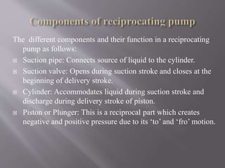
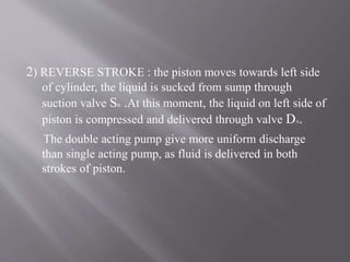
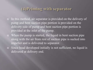
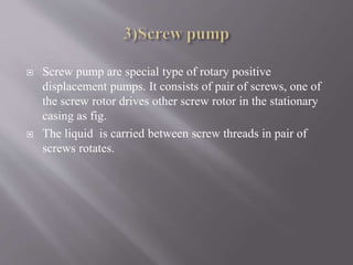
![ These pump operate on the principle of a definite quantity
of liquid is discharged or displaced due to the positive or
real displacement of working elements.
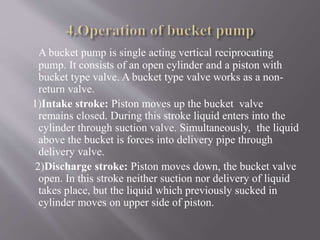
1) Reciprocating pump
[i] piston pumps [ii] plunger pump [iii] bucket
pump(hand-pump)
2) Rotary pump
[i] gear pump [ii] vane pump [iii] screw pump](https://image.slidesharecdn.com/pumpeme-141022040110-conversion-gate01/85/Pump-eme-6-320.jpg)
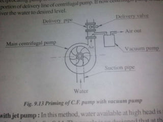
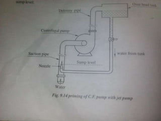
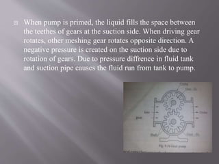
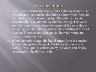
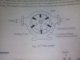


The document discusses different types of pumps including reciprocating pumps, centrifugal pumps, and rotary pumps. It provides details on their working principles, main components, classifications, advantages and disadvantages. Reciprocating pumps are positive displacement pumps that use reciprocating pistons or plungers to pump fluids. Centrifugal pumps are rotodynamic pumps that use an impeller to increase the velocity and pressure of a fluid. Rotary pumps include gear pumps, vane pumps, and screw pumps, which use rotating gears, vanes or screws to pump fluids through positive displacement.