3. 3
Introduction
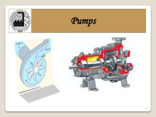
A pump is a mechanical device which can transfer
rotational energy (mechanical energy) of the machine to
the potential or kinetic energy of the liquid.
A pump may be defined as machine when driven from
some external source (electric motor, turbine or an
engine) transfer/lifts liquid or semi-solid fluid from one
place to another.
7. 7
Reciprocating pump
• A reciprocating pump is a positive displacement machine
• It traps a fixed volume of liquid at near-suction conditions,
compresses it to discharge pressure, and pushes it out the discharge
nozzle
• The basic principle involved is that a plunger or piston will displace
a quantity of liquid equal to its swept volume.
In Figure, plunger A is lowered into the container, displacing liquid
which flows into container B
Plunger
In a reciprocating pump, reciprocating
motion is accomplished by a piston or
plunger, or diaphragm.
8. 8
Reciprocating pump
Figure depicts the suction stroke of a plunger pump. When the plunger
moves away from the head end of the cylinder, the discharge check
valve is held closed by the higher pressure in the discharge pipe
compared to the lower pressure in the liquid cylinder. This lower
pressure in the liquid cylinder also causes the suction valve to be
opened by the higher pressure in the suction line. Fluid then flows into
the cylinder until the plunger reaches the end of its travel.
9. 9
Reciprocating pump
Figure depicts the discharge stroke of a plunger pump. As the plunger
moves toward the head end, the increasing pressure in the cylinder
closes the suction valve. The pressure in the cylinder continues to rise
until it exceeds the pressure in the discharge line and the discharge
valve opens, releasing the volume of fluid displaced by the plunger.
11. 11
Rotary pump
Rotary pumps are positive displacement pumps, but unlike
reciprocating pumps, have relatively steady, non-pulsating flow.
Rotation of the rotor(s) within the casing traps pockets of liquid at
suction conditions, elevates the fluid pressure, and then pushes the
fluid out the discharge.
Can handle debris
Used to raise the level of
wastewater
Abrasive material will
damage the seal between
screw and the housing
Grain augers use the same
principle
12. 12
Rotary pump
Gear Pump
fluid is trapped between gear
teeth and the housing
Two-lobe Rotary Pump
(gear pump with two “teeth” on
each gear)
same principle as gear pump
fewer chambers - more extreme
pulsation
14. 14
Peristaltic Pump
Fluid only contacts tubing
Tubing ID and roller velocity
with respect to the tubing
determine flow rate
Tubing eventually fails from
fatigue and abrasion
Fluid may leak past roller at
high pressures
Viscous fluids may be pumped
more slowly
15. 15
Centrifugal Pump
• Centrifugal pump is a machine consisting of a set of rotating vanes
enclosed within housing or casing.
• Centrifugal pump convert energy of a prime mover (a electric motor
or turbine) first into velocity or kinetic energy and then into pressure
energy of a fluid that is being pumped.
• The energy changes occur by virtue of two main parts of the pump:
i. Impeller - is the rotating part that converts driver energy into
the kinetic energy
ii. Volute or diffuser-is the stationary part that converts the kinetic
energy into pressure energy.
16. 16
Centrifugal Pump
• The process liquid enters the suction nozzle and then into eye
(center) of a revolving device known as an impeller. When the
impeller rotates, it spins the liquid sitting in the cavities between the
vanes outward and provides centrifugal acceleration. As liquid leaves
the eye of the impeller a low-pressure area is created causing more
liquid to flow toward the inlet. Because the impeller blades are
curved, the fluid is pushed in a tangential and radial direction by the
centrifugal force.
17. 17
Centrifugal Pump
• The faster the impeller the faster the liquid moves .
• Centrifugal force pushes the liquid outward from the eye and enters the
casing . Thus liquid velocity decreases & its pressure increases.
• The head (pressure in terms of height of liquid) developed is
approximately equal to the velocity energy at the periphery of the
impeller expressed by the following well-known formula:
where:
H = Total Head developed in feet
v = Velocity at periphery of impleller in ft/s
g = Acceleration due to gravity = 32.2 ft/s2
19. 19
Components of
Centrifugal Pump
A centrifugal pump has two main components:
1. Stationary Components:
i. Casings: A Casing is provided for housing the impeller
& supporting the bearings provided with the shaft. Also
casing has a provision for connecting with suction &
discharge pipe liens. Casing are three types:
• Volute Casings
• Volute with vortex or whirlpool casing
•Diffuser or turbine casing
20. 20
Components of
Centrifugal Pump
Volute casings:
• A volute is a curved funnel increasing in area to the discharge
port. As the area of the cross-section increases, the volute reduces
the speed of the liquid and increases the pressure of the liquid.
• These casings can convert only a small amount of velocity head
into pressure head and a large amount of velocity head is lost in
eddies, thus produce comparatively low heads.
21. 21
Components of
Centrifugal Pump
Vortex or whirlpool casing:
• Like volute casing with a circular vortex or whirlpool chamber
between the impeller & the volute.
• Vortex chamber converts some of the kinetic energy into
potential energy with slight loss by friction.
• More efficient than volute casing or volute pump.
22. 22
Components of
Centrifugal Pump
Diffuser or turbine casing:
• In this system the impeller is surrounded by a series of stationary guide
vanes or by a diffuser ring with guide vanes which by their divergence
furnish gradually expanding passages for the liquid to follow after leaving
the impeller.
• In this process direction of flow is changed and velocity head is converted to
pressure head before the liquid enters the volute.
• Velocity head of the liquid leaving the impeller is completely converted into
pressure than in the volute type
• Under variable conditions of speed and discharge the efficiency of the pump
goes down since the diffuser is generally designed for one rate of discharge
at a given impeller speed.
• Costlier than volute pump
• Pumps having diffuser type casing are commonly known as Turbine pumps.
23. 23
Components of
Centrifugal Pump
ii. Casing Wear rings- act as the seal between the casing
and the impeller to restrict leakage of high pressure
liquid back to the pump suction.
iii. Suction and Discharge Nozzles.
24. 24
Components of
Centrifugal Pump
iv. Seal Chamber and Stuffing Box:
When the sealing is achieved by means of a mechanical seal, the chamber is
commonly referred to as a Seal Chamber.
When the sealing is achieved by means of packing, the chamber is referred to
as a Stuffing Box.
Both the seal chamber and the stuffing box have the primary function of
protecting the pump against leakage from the gap between the pump casing
and the shaft.
The seal chambers and stuffing boxes are also provided with cooling or
heating arrangement for proper temperature control.
25. 25
Components of
Centrifugal Pump
v. Glands
The gland is a very important part of the seal chamber or the
stuffing box. It gives the packings or the mechanical seal the
desired fit on the shaft sleeve. It can be easily adjusted in axial
direction.
vi. Bearing Housing
The bearing housing encloses the bearings mounted on the shaft.
The bearings keep the shaft or rotor in correct alignment with the
stationary parts under the action of radial and transverse loads.
The bearing house also includes an oil reservoir for lubrication,
constant level oiler, jacket for cooling by circulating cooling
water.
27. 27
Impeller
• It is the main part of pump assembly fitted with a series of
backward vanes (or blades). The function of the impeller
is to force the liquid into a rotary motion by centrifugal
force.
• On the basis of construction can be classified as:
i. Closed or shrouded impeller: contains two shrouds (or
side walls) in which plain or curved vanes are inserted.
ii. Semi-open impeller: Vanes are fixed on one shroud
only.
iii. Open type impeller: Vanes are directly fixed on the
web. There is no shroud.
29. 29
Shaft
The basic purpose of a centrifugal pump shaft is to
transmit the torques encountered when starting and
during operation while supporting the impeller and other
rotating parts. It must do this job with a deflection less
than the minimum clearance between the rotating and
stationary parts.
30. 30
Shaft sleeves
Pump shafts are usually protected from erosion, corrosion, and wear
at the seal chambers, leakage joints, internal bearings, and in the
waterways by renewable sleeves. Unless otherwise specified, a shaft
sleeve of wear, corrosion, and erosion-resistant material shall be
provided to protect the shaft. The sleeve shall be sealed at one end.
The shaft sleeve assembly shall extend beyond the outer face of the
seal gland plate. (Leakage between the shaft and the sleeve should not
be confused with leakage through the mechanical seal).
.
31. 31
Coupling
Couplings can compensate for axial growth of the shaft and
transmit torque to the impeller.
Shaft couplings can be broadly classified into two groups:
rigid and flexible.
Rigid couplings are used in applications where there is
absolutely no possibility or room for any misalignment.
Flexible shaft couplings are more prone to selection,
installation and maintenance errors. Flexible shaft couplings
can be divided into two basic groups: elastomeric and non-
elastomeric.
32. 32
Axial flow pump
• An axial flow pump is one in which the fluid enters parallel to the axis
of rotation and leaves in the axial tangential plane.
• Axial flow pumps are normally designed for conditions where low head
high flows
Axial flow pumps are sometimes called propeller pumps because they
operate essentially the same as the propeller of a boat.
34. 34
Radial flow pump
Radial flow pumps operate at higher pressures and lower flow rates than
axial and mixed flow pumps.
• Also called Centrifugal Pump pumps
• broad range of applicable flows and heads
• higher heads can be achieved by increasing the diameter or
the rotational speed of the impeller
Radial flow pumps are those where the fluid enters the impeller
in a direction parallel with the axis of rotation and leaves the
impeller in the radial tangential plane.
35. 35
Mixed flow pump
• Mixed flow pumps, as the name suggests, function as a compromise
between radial and axial flow pumps
• fluid experiences both acceleration in radial and the axial direction
• As a consequence mixed flow pumps operate at higher pressures than
axial flow pumps while delivering higher discharges than radial flow
pumps
37. 37
Starting of
centrifugal pump
A typical starting sequence for a centrifugal pump is:
• Ensure that all valves in auxiliary sealing, cooling, and
flushing system piping are open, and that these systems are functioning
properly.
• Close discharge valve.
• Open suction valve.
• Vent gas from the pump and associated piping.
• Energize the driver.
• Open discharge valve slowly so that the flow increases gradually.
41. 41
Pumps performance
Effects of Changing Liquid Specific Gravity
Specific gravity (S.G.) has the following effects on pump performance,
assuming constant rpm and impeller diameter:
1. Flow rate (quantity) is unchanged by S.G. (although the flow reading on
a differential-pressure flow meter varies.)
2. Pressure varies directly with S.G. (Although pressure varies, head is
constant.)
3. Horsepower varies directly with S.G.
These relationships are important when converting a pump to another
service or if significant changes to fluid gravity are anticipated. For
example, converting from a light hydrocarbon service to water service may
significantly overload an existing driver.
42. 42
Matching pumps to system
characteristics
Good piping system design
◦ Match system characteristics to pump curve
Trimming pump impellers
◦ To reduce flow
◦ To match partload requirments
Pump control
◦ Two-speed pumping & motors
◦ Variable speed pumping
◦ Source distribution pumping
43. 43
Matching pumps to system
characteristics
• Modulation of pump-piping systems
• Throttle volume flow by using a valve
• Change flow resistance – new system curve
• Also known as “riding on the curve”
• Turn water pumps on or off in sequence
• Sudden increase/drop in flow rate and head
• Vary the pump speed
• System operating point move along the system curve
• Requires the lowest pump power input
44. 44
Matching pumps to system
characteristics
Plant loop (at constant flow) (production loop)
◦ To protect evaporator from freezing, a fairly constant-
volume water flow is required
Building loop (at variable flow)
◦ For saving energy at partload
◦ A differential pressure transmitter is often installed at
the farthest end from the pump
Primary-secondary loop
◦ A short common pipe connects the 2 loops
45. 45
Matching pumps to system
characteristics
Series and Parallel Operation
Often pumps are installed in series or in parallel with other pumps.
In parallel, the capacities at any given head are added; in series, the heads
at any given capacity are added.
Figures show series and parallel pumps curves, a system curve, and the
effect of operating one, two or three pumps in a system.
In both figures, the operating points for both pumps "A" and "B" are the
same only when one pump is operating.
For 2 or 3 pumps operating, the points are not the same because of the
pump curve shapes. Hence, due consideration should be given to the pump
curve shape when selecting pumps for series or parallel operation.
50. 50
Common problems
• Low Performance
• Cavitation
• Seal Leakage
• Bearings Failure
• Vibration
• Noise
51. 51
Cavitation
The formation of vapor bubbles in the impeller suction eye due to fluid flashing or
boiling, with subsequent collapse of the bubbles as the pressure rises, is called
cavitation. Cavitation may cause vibration, pitting damage, and impaired
performance. Cavitation may or may not be serious depending on the pump,
HP/stage, impeller design, and the fluid being pumped. In small pumps with low
differential head per stage, the energy of collapsing bubbles is much less than in
larger, high-head-per-stage pumps. Cavitation is more severe in a single-boiling
point fluid (like water) than with a mixture (like petroleum stocks) that have a
broad boiling range.
52. 52
NPSH
NPSHA: is technically defined as the total suction pressure (in psia) at the
suction nozzle less the true vapor pressure of the liquid (in psia) at the
pumping temperature. For centrifugal pumps, NPSHA is always expressed
in feet of the liquid pumped. For reciprocating pumps it includes the
acceleration head. NPSHA depends on the system characteristics, liquid
properties and operating conditions.
NPSHR: The minimum total suction absolute head, at the suction nozzle
minus the liquid vapor absolute pressure head, at flowing temperature,
required to avoid cavitation. For positive displacement pumps it includes
internal acceleration head and losses caused by suction valves and effect of
springs. It does not include system acceleration head.
NPSHR depends on the pump characteristics and speed, liquid properties
and flow rate and is determined by vendor testing, usually with water.
53. 53
NPSH
Calculation of NPSHA
NPSHA can be calculated as follows:
NPSHA = H + S - F – Vp
where: NPSHA = feet of head of the pumped liquid, at the pump
impeller-eye elevation and suction flange face.
H = minimum absolute pressure on the surface of liquid
pumped, in feet of the liquid.
S = static head, or vertical distance between the surface
of the liquid and the center of the impeller, in feet.
S is negative (-) when the pump is above liquid
surface, and positive (+) when the pump is below.
F = friction losses, in the suction pipe and fittings, in
feet of the liquid.
VP = True vapor pressure of the liquid,