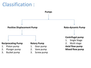
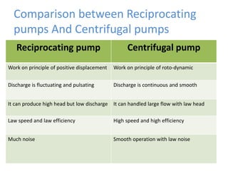
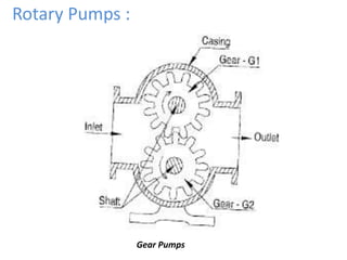
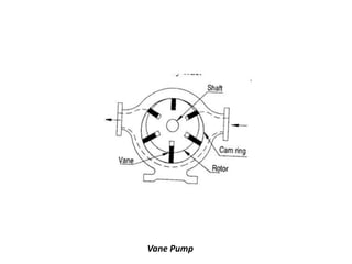
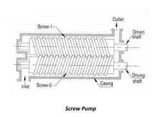
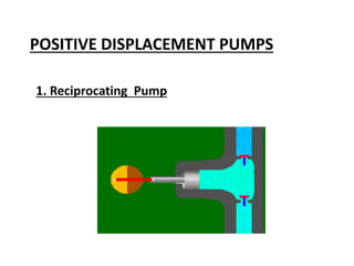
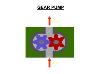
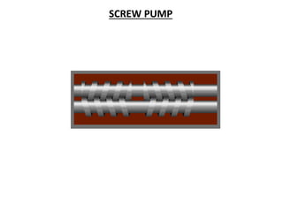
Pumps
Introduction
• Pump is mechanical device which conveys liquid
from one place to another place.
• Pump is a “Hydraulic Machines which convert the
mechanical energy into hydraulic energy”.
• The pump is a power consuming machines.
• The power can be supplied to the pump by a prime
mover like an Electric motor, I.C.Engine or Turbine.
• Pumping means addition of energy to a liquid. And
this is done by means of Piston, Plunger, Impeller,
Gears, Screw etc.
• The purpose of pump is to increase the pressure,
Imparting kinetic energy, lifting and circulating,
Exhausting liquids etc.
Classification :
Positive Displacement Pump
Centrifugal pump
1. Single Stage
2. Multi stage
Axial flow pump
Mixed flow pump
Reciprocating Pump
1. Piston pump
2. Plunger pump
3. Bucket pump
Rotary Pump
1. Gear pump
2. Vane pump
3. Screw pump
Roto-dynamic Pump
Pumps
Terminology of Pumps:
1) Head :
In the pumps, different forms of energy are expressed in
terms of height is called “Head”.
2) Suction Head (hs) :
It is the vertical height of the centre line of pump shaft above
the surface of liquid.
3) Delivery Head (hd) :
It is the vertical height of the centre line of pump shaft to
where the liquid is delivered.
4) Velocity Head (hv) :
It is kinetic energy carried by the liquid at the end of delivery
pipe. Hv = V2 / 2g
5) Static Head (hst):
It is the sum of Suction and Delivery head.
hst = hs + hd
6) Manometric Head (Hm) :
It is the total head required to develop by the pump.
Hm = hs + hd + hfs + hfd + hfp + hv
Where hfs = Friction head loss in Suction pipe
hfd = Friction head loss in delivery pipe
hfp = Friction head loss inside pump
7) Water power (Pw) :
It is the power required by pump to handle the liquid to
develop manometric head.
Pw = ρ g Q Hm
Where, ρ = density of liquid (Kg/m3)
Q = liquid discharge by pump (m3/s)
Hm = manometric head in meter
8) Shaft power (Ps) :
It is the power input to the pump shaft by motor.
9) Efficiency of Pump :
It is the ratio of Water power to Shaft power.
np = Pw / Ps * 100 %
Reciprocating Pump :
• According to type of reciprocating member of the
pump :
1. Piston Pump
2. Plunger Pump
3. Bucket Pump (Non return type valve)
• According to the action of liquid on piston :
1. Single Acting Pump
2. Double Acting Pump
• According to method of drive :
1. Direct Acting Pump
2. Power Pump
Operation of Single Acting Reciprocating
Pump :
• Forward Stroke : 0° to 180°
• Reverse Stroke : 180° to 360°
Single Acting Reciprocating Pump
Operation of Double Acting Reciprocating
Pump :
Operation of
Plunger Pump :
Operation of Bucket Pump :
Calculations for Reciprocating Pumps :
1) Discharge :
Volume flow rate through pump,
Q = Volume displaced in delivery Stroke x No. of cycles per
second
Q = LA x (N/60) …...............For Single Acting pump
Q = LA x (2N/60) …...............For Double Acting pump
Where, L = Length of Stroke
A = Cross Sectional Area of Piston
N = Speed of pump in RPM
2) Power required to drive pump :
P = Discharge rate x Pressure to be developed
= Q x ρgHm
Considering friction losses and leakage losses, The power required
by the pump is as,
Where np = Pump Efficiency
The power required at motor shaft to drive pump,
Where no = Overall Efficiency
= np x ncoupling x nmotor
3) Co-efficient of discharge (Cd):
It is the ratio of actual discharge to theoritical discharge
Where , Qa = Actual Discharge
Q = Theoritical Discharge
4) Slip :
It is measure of return of water through the valves or the
leakage of water from the delivery to suction head
Air Chamber :
Centrifugal Pump :
• Main parts of C.F. pump
1. Impeller
2. Casing
3. Suction pipe with foot valve and a strainer
4. Delivery pipe
• Types of C.F. pump :
1. According to type of casing
a) Volute o Spiral Type Pump
b) Vortex Type Pump
c) Diffuser Type Pump
2. According to no. of stages
a) Multi Stage b) Impeller in series c) Impeller in parallel
Main Parts of Centrifugal Pumps
• which is the rotating part of
the centrifugal pump.
• It consists of a series of
backwards curved vanes
(blades).
• The impeller is driven by a
shaft which is connected to the
shaft of an electric motor.
1. Impeller:
Volute Type Pump :
•Volute casing provide
gradual increase in
area to the discharge
pipe.
•The liquid leaving the
impeller enters the
volute chamber with
high velocity.
•Pressure is increases
due to gradually
increase in area of
casing.
Main Parts of Centrifugal Pumps
• Which is an air-tight
passage surrounding the
impeller
• designed to direct the
liquid to the impeller
and lead it away
• Volute casing. It is of
spiral type in which the
area of the flow
increases gradually.
2. Casing
Vortex Type Pump :
Diffuser Type Pump :
Reciprocating pump Centrifugal pump
Work on principle of positive displacement Work on principle of roto-dynamic
Discharge is fluctuating and pulsating Discharge is continuous and smooth
It can produce high head but low discharge It can handled large flow with law head
Law speed and law efficiency High speed and high efficiency
Much noise Smooth operation with law noise
Comparison between Reciprocating
pumps And Centrifugal pumps
Priming of C.F. Pump :
The priming is operation of filling passage ways
(suction pie , casing and delivery pipe upto
delivery valve) from outside source with the
liquid to be raised by the pump before starting
the pump. Thus the air from passageways is
removed and filled with the liquid to be
pumped.
Methods of priming
• Manually
• Priming with vacuum pump
• Priming with jet pump
• Priming with seperator
Rotary Pumps :
Gear Pumps
Vane Pump
Screw Pump
POSITIVE DISPLACEMENT PUMPS
1. Reciprocating Pump
GEAR PUMP
OUTLET
INLET
SCREW PUMP
Chap 9 pumps eme

Chap 9 pumps eme

  • 1.
  • 2.
    Introduction • Pump ismechanical device which conveys liquid from one place to another place. • Pump is a “Hydraulic Machines which convert the mechanical energy into hydraulic energy”.
  • 3.
    • The pumpis a power consuming machines. • The power can be supplied to the pump by a prime mover like an Electric motor, I.C.Engine or Turbine. • Pumping means addition of energy to a liquid. And this is done by means of Piston, Plunger, Impeller, Gears, Screw etc. • The purpose of pump is to increase the pressure, Imparting kinetic energy, lifting and circulating, Exhausting liquids etc.
  • 4.
    Classification : Positive DisplacementPump Centrifugal pump 1. Single Stage 2. Multi stage Axial flow pump Mixed flow pump Reciprocating Pump 1. Piston pump 2. Plunger pump 3. Bucket pump Rotary Pump 1. Gear pump 2. Vane pump 3. Screw pump Roto-dynamic Pump Pumps
  • 5.
    Terminology of Pumps: 1)Head : In the pumps, different forms of energy are expressed in terms of height is called “Head”. 2) Suction Head (hs) : It is the vertical height of the centre line of pump shaft above the surface of liquid. 3) Delivery Head (hd) : It is the vertical height of the centre line of pump shaft to where the liquid is delivered. 4) Velocity Head (hv) : It is kinetic energy carried by the liquid at the end of delivery pipe. Hv = V2 / 2g
  • 6.
    5) Static Head(hst): It is the sum of Suction and Delivery head. hst = hs + hd 6) Manometric Head (Hm) : It is the total head required to develop by the pump. Hm = hs + hd + hfs + hfd + hfp + hv Where hfs = Friction head loss in Suction pipe hfd = Friction head loss in delivery pipe hfp = Friction head loss inside pump
  • 7.
    7) Water power(Pw) : It is the power required by pump to handle the liquid to develop manometric head. Pw = ρ g Q Hm Where, ρ = density of liquid (Kg/m3) Q = liquid discharge by pump (m3/s) Hm = manometric head in meter 8) Shaft power (Ps) : It is the power input to the pump shaft by motor. 9) Efficiency of Pump : It is the ratio of Water power to Shaft power. np = Pw / Ps * 100 %
  • 8.
    Reciprocating Pump : •According to type of reciprocating member of the pump : 1. Piston Pump 2. Plunger Pump 3. Bucket Pump (Non return type valve) • According to the action of liquid on piston : 1. Single Acting Pump 2. Double Acting Pump • According to method of drive : 1. Direct Acting Pump 2. Power Pump
  • 9.
    Operation of SingleActing Reciprocating Pump : • Forward Stroke : 0° to 180° • Reverse Stroke : 180° to 360°
  • 10.
  • 11.
    Operation of DoubleActing Reciprocating Pump :
  • 12.
  • 13.
  • 14.
    Calculations for ReciprocatingPumps : 1) Discharge : Volume flow rate through pump, Q = Volume displaced in delivery Stroke x No. of cycles per second Q = LA x (N/60) …...............For Single Acting pump Q = LA x (2N/60) …...............For Double Acting pump Where, L = Length of Stroke A = Cross Sectional Area of Piston N = Speed of pump in RPM
  • 15.
    2) Power requiredto drive pump : P = Discharge rate x Pressure to be developed = Q x ρgHm Considering friction losses and leakage losses, The power required by the pump is as, Where np = Pump Efficiency The power required at motor shaft to drive pump, Where no = Overall Efficiency = np x ncoupling x nmotor
  • 16.
    3) Co-efficient ofdischarge (Cd): It is the ratio of actual discharge to theoritical discharge Where , Qa = Actual Discharge Q = Theoritical Discharge 4) Slip : It is measure of return of water through the valves or the leakage of water from the delivery to suction head
  • 17.
  • 18.
    Centrifugal Pump : •Main parts of C.F. pump 1. Impeller 2. Casing 3. Suction pipe with foot valve and a strainer 4. Delivery pipe • Types of C.F. pump : 1. According to type of casing a) Volute o Spiral Type Pump b) Vortex Type Pump c) Diffuser Type Pump 2. According to no. of stages a) Multi Stage b) Impeller in series c) Impeller in parallel
  • 20.
    Main Parts ofCentrifugal Pumps • which is the rotating part of the centrifugal pump. • It consists of a series of backwards curved vanes (blades). • The impeller is driven by a shaft which is connected to the shaft of an electric motor. 1. Impeller:
  • 21.
    Volute Type Pump: •Volute casing provide gradual increase in area to the discharge pipe. •The liquid leaving the impeller enters the volute chamber with high velocity. •Pressure is increases due to gradually increase in area of casing.
  • 22.
    Main Parts ofCentrifugal Pumps • Which is an air-tight passage surrounding the impeller • designed to direct the liquid to the impeller and lead it away • Volute casing. It is of spiral type in which the area of the flow increases gradually. 2. Casing
  • 23.
  • 24.
  • 25.
    Reciprocating pump Centrifugalpump Work on principle of positive displacement Work on principle of roto-dynamic Discharge is fluctuating and pulsating Discharge is continuous and smooth It can produce high head but low discharge It can handled large flow with law head Law speed and law efficiency High speed and high efficiency Much noise Smooth operation with law noise Comparison between Reciprocating pumps And Centrifugal pumps
  • 26.
    Priming of C.F.Pump : The priming is operation of filling passage ways (suction pie , casing and delivery pipe upto delivery valve) from outside source with the liquid to be raised by the pump before starting the pump. Thus the air from passageways is removed and filled with the liquid to be pumped.
  • 27.
    Methods of priming •Manually • Priming with vacuum pump • Priming with jet pump • Priming with seperator
  • 28.
  • 29.
  • 30.
  • 32.
  • 33.
  • 34.