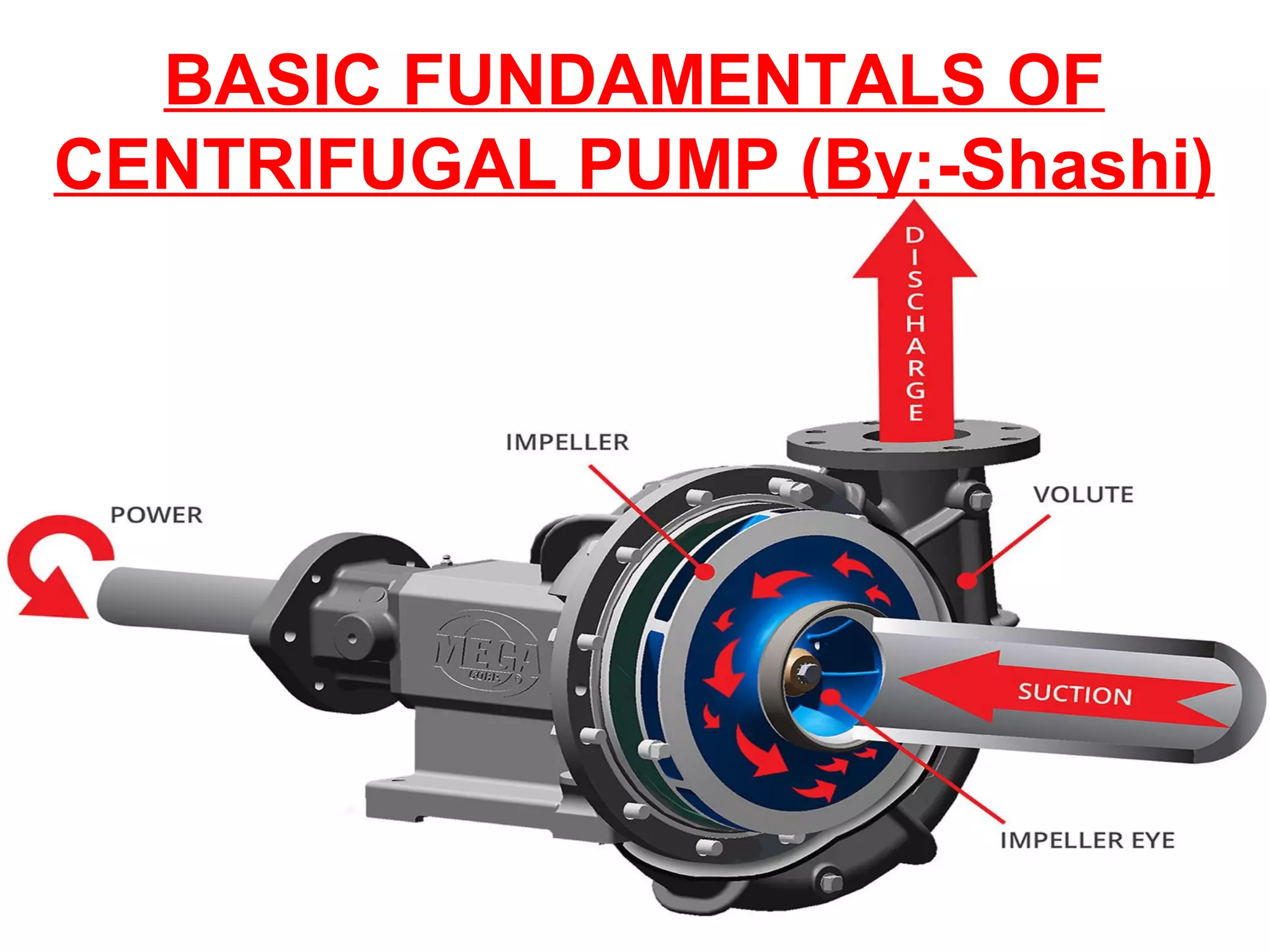
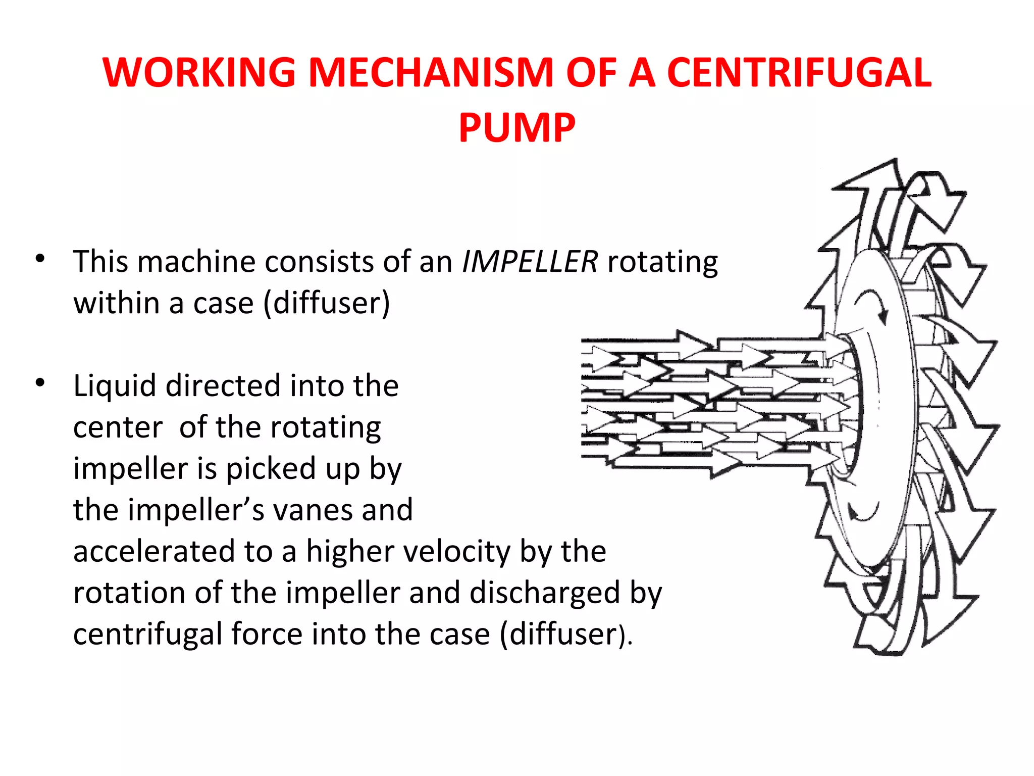
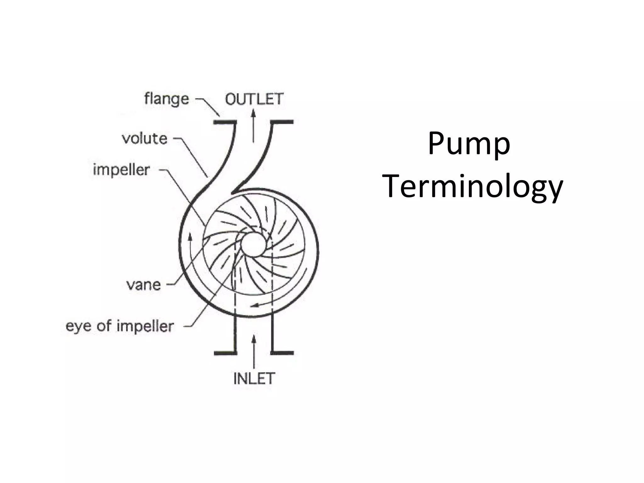
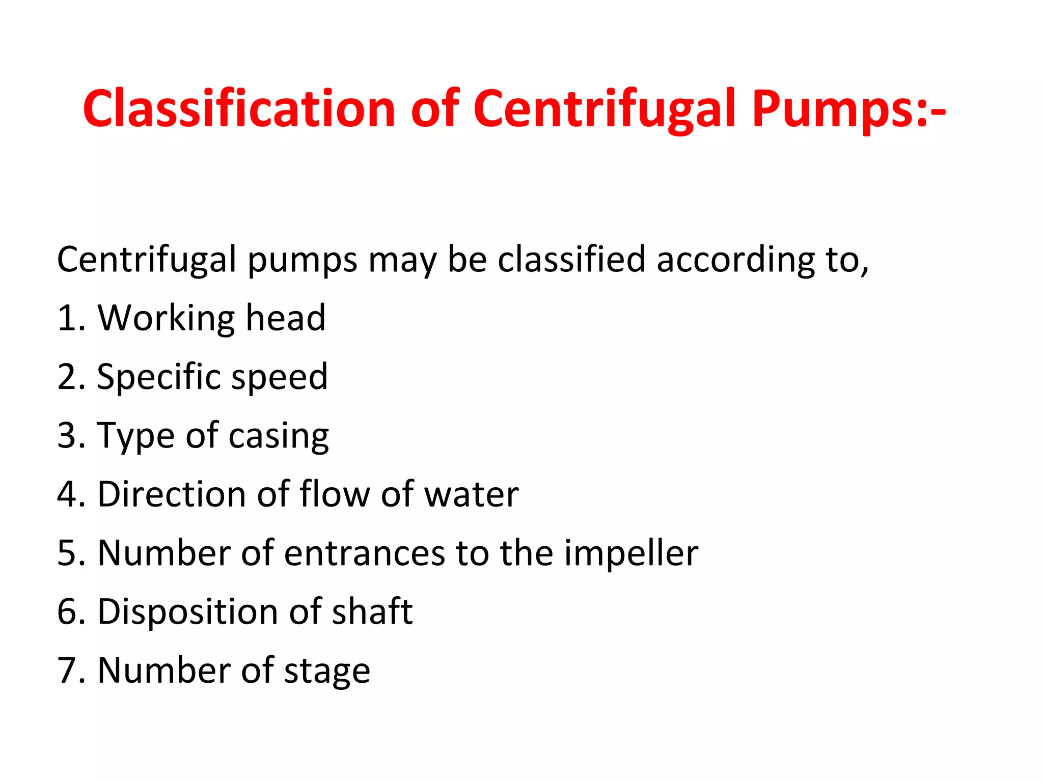
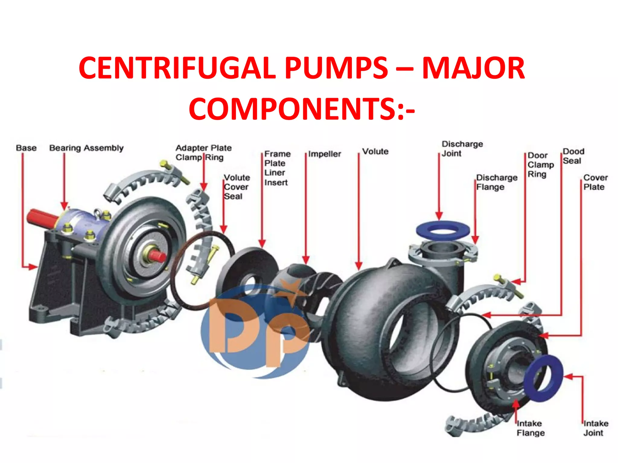
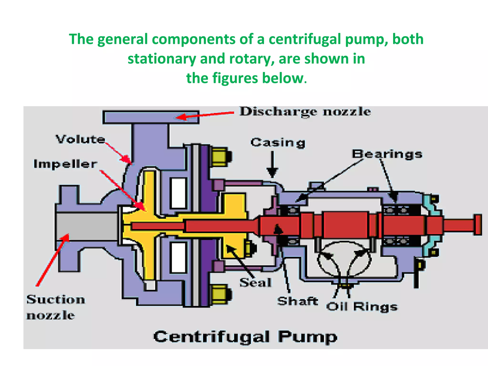
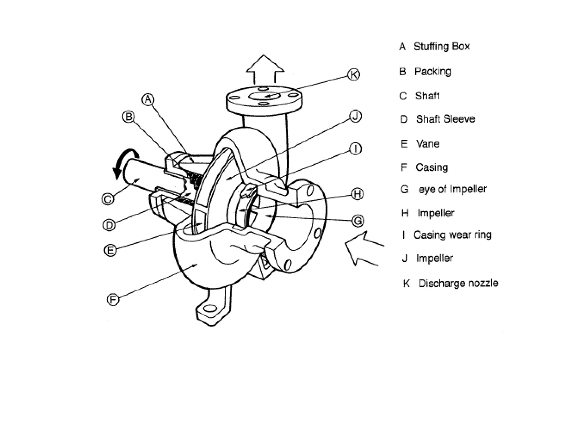
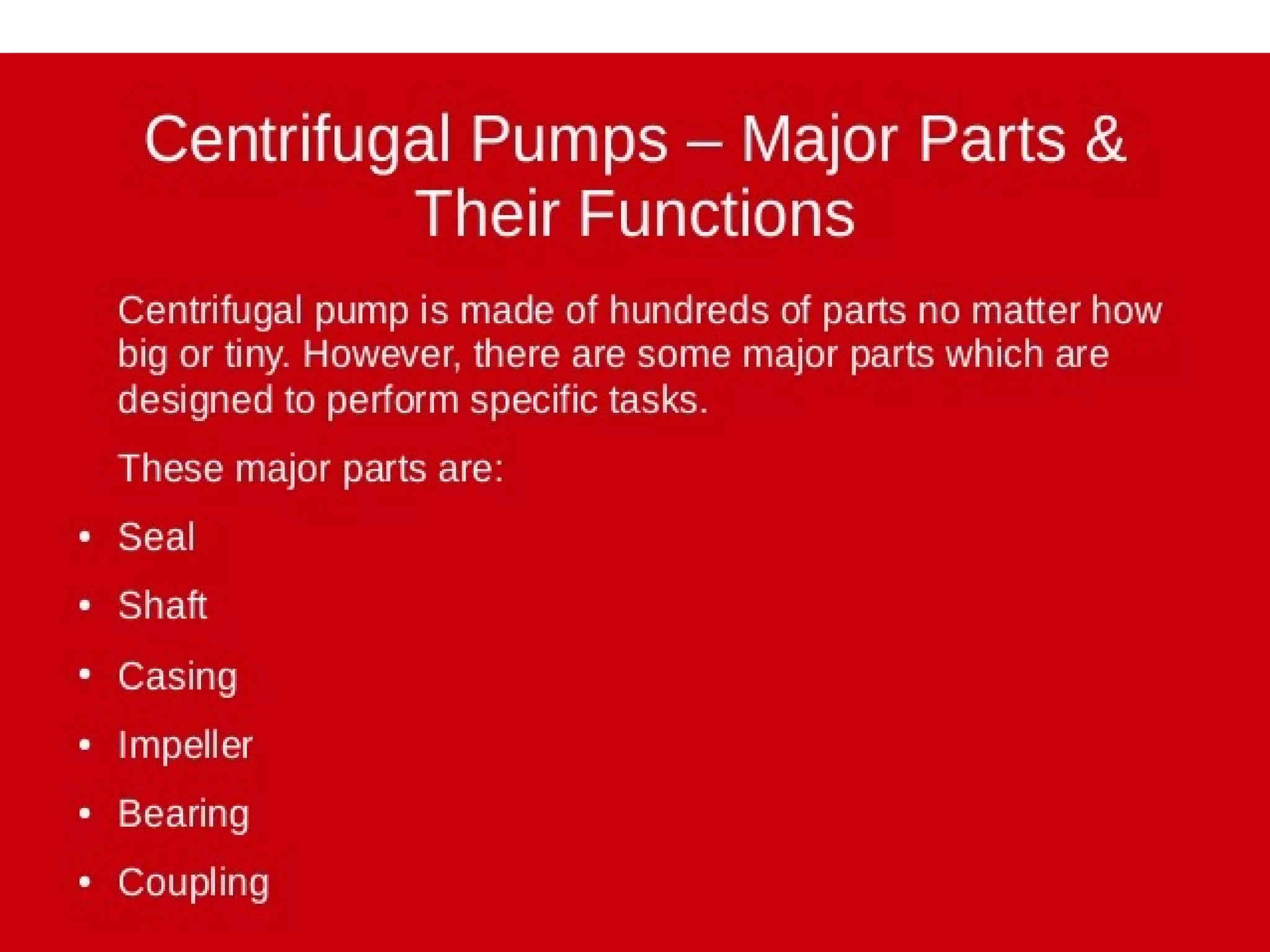
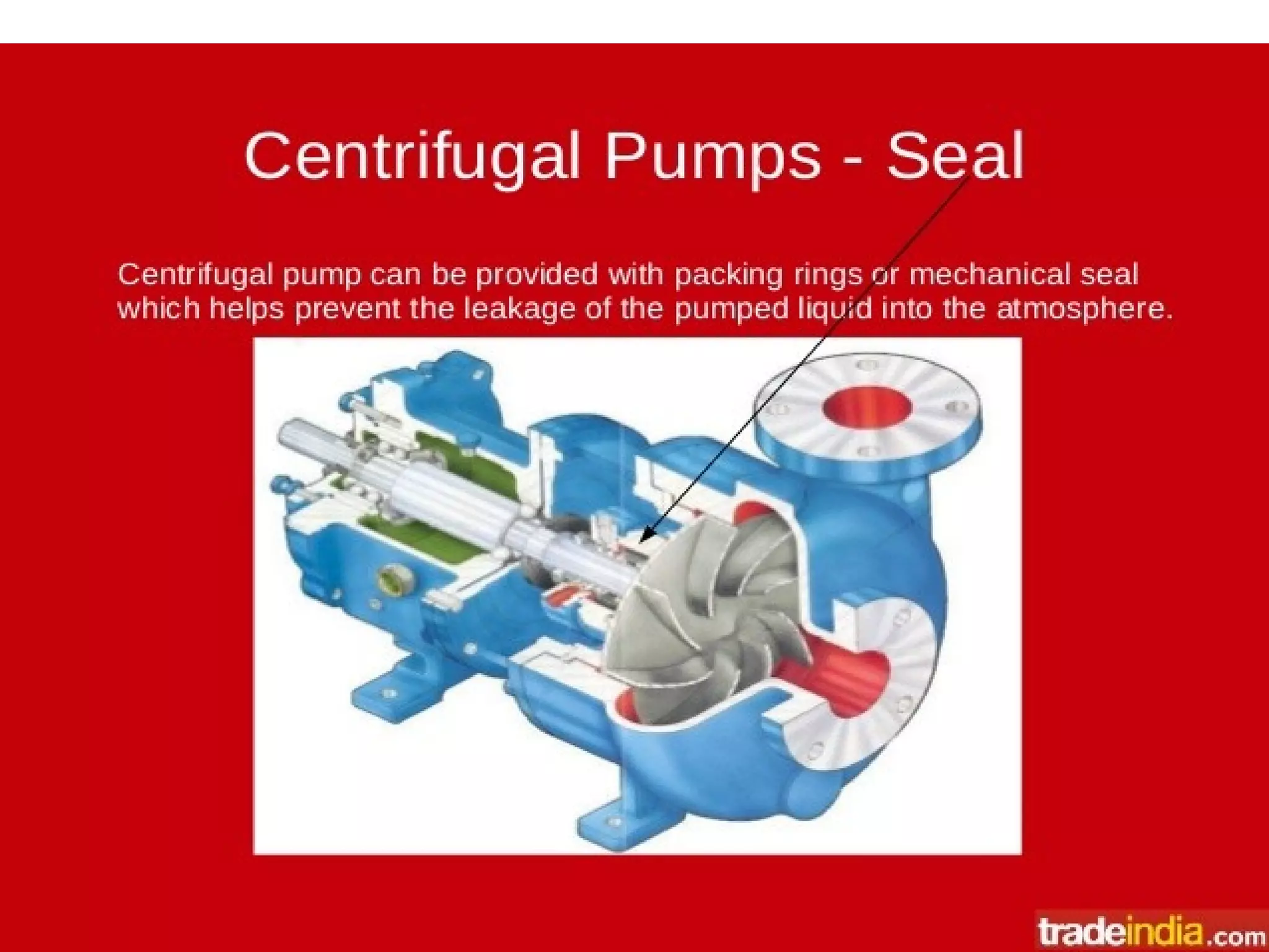
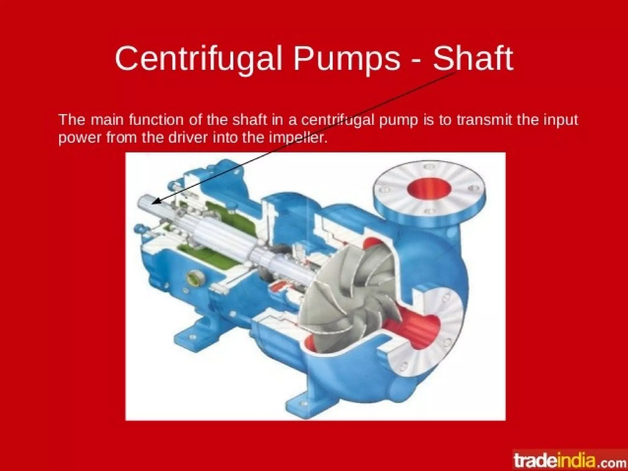
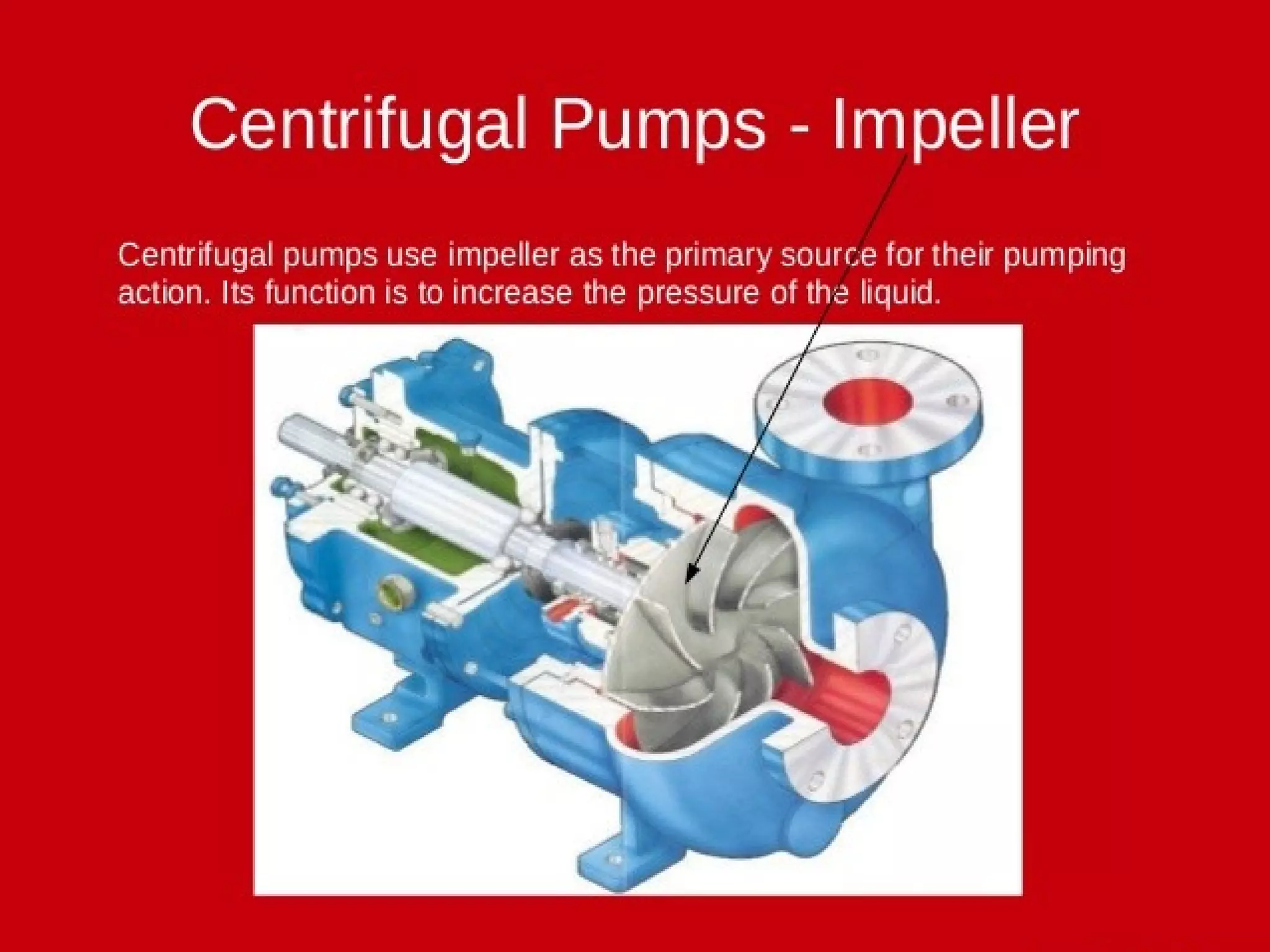
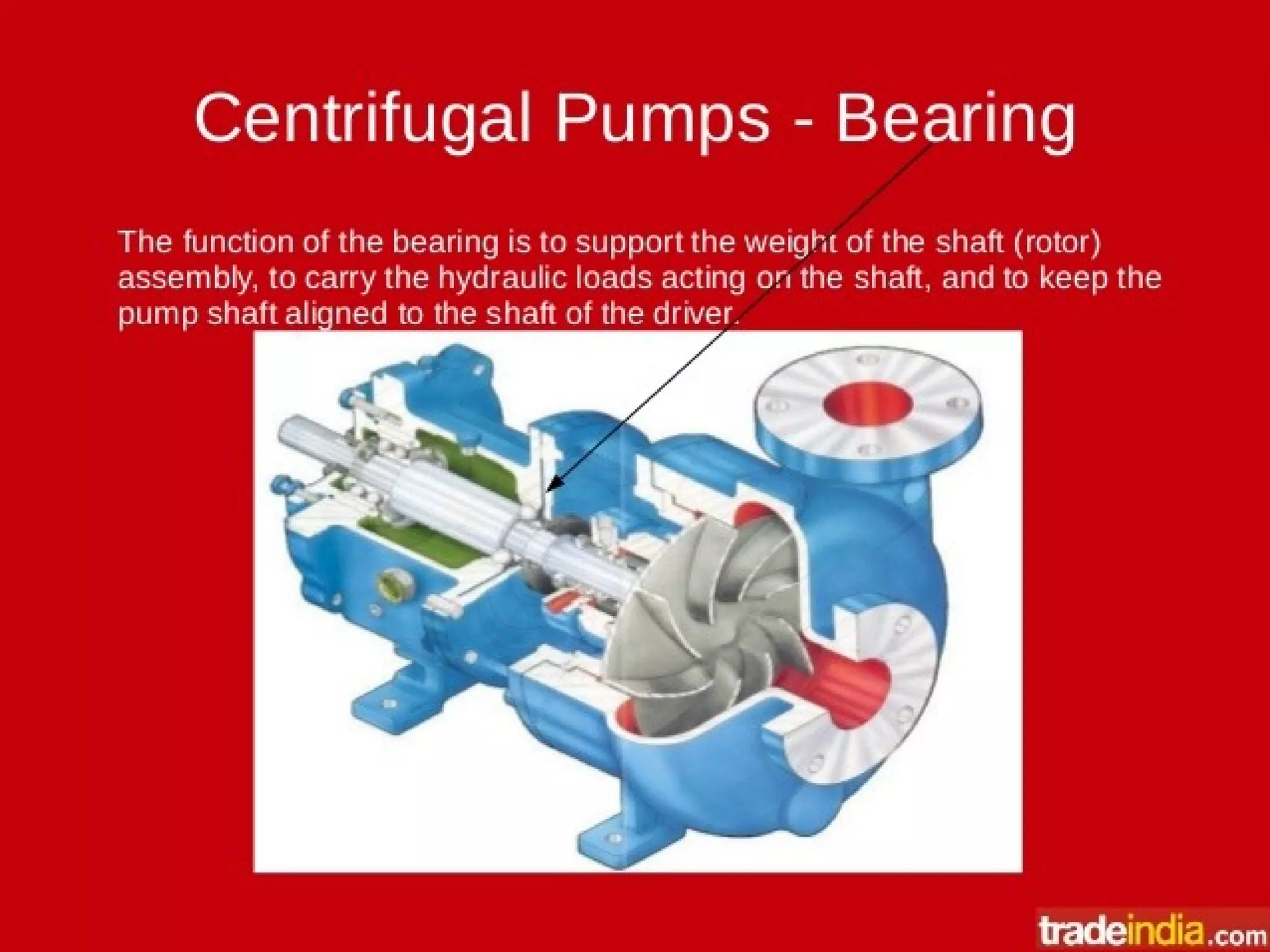
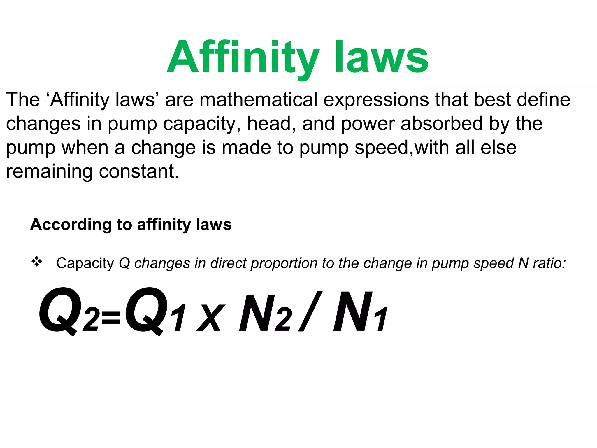
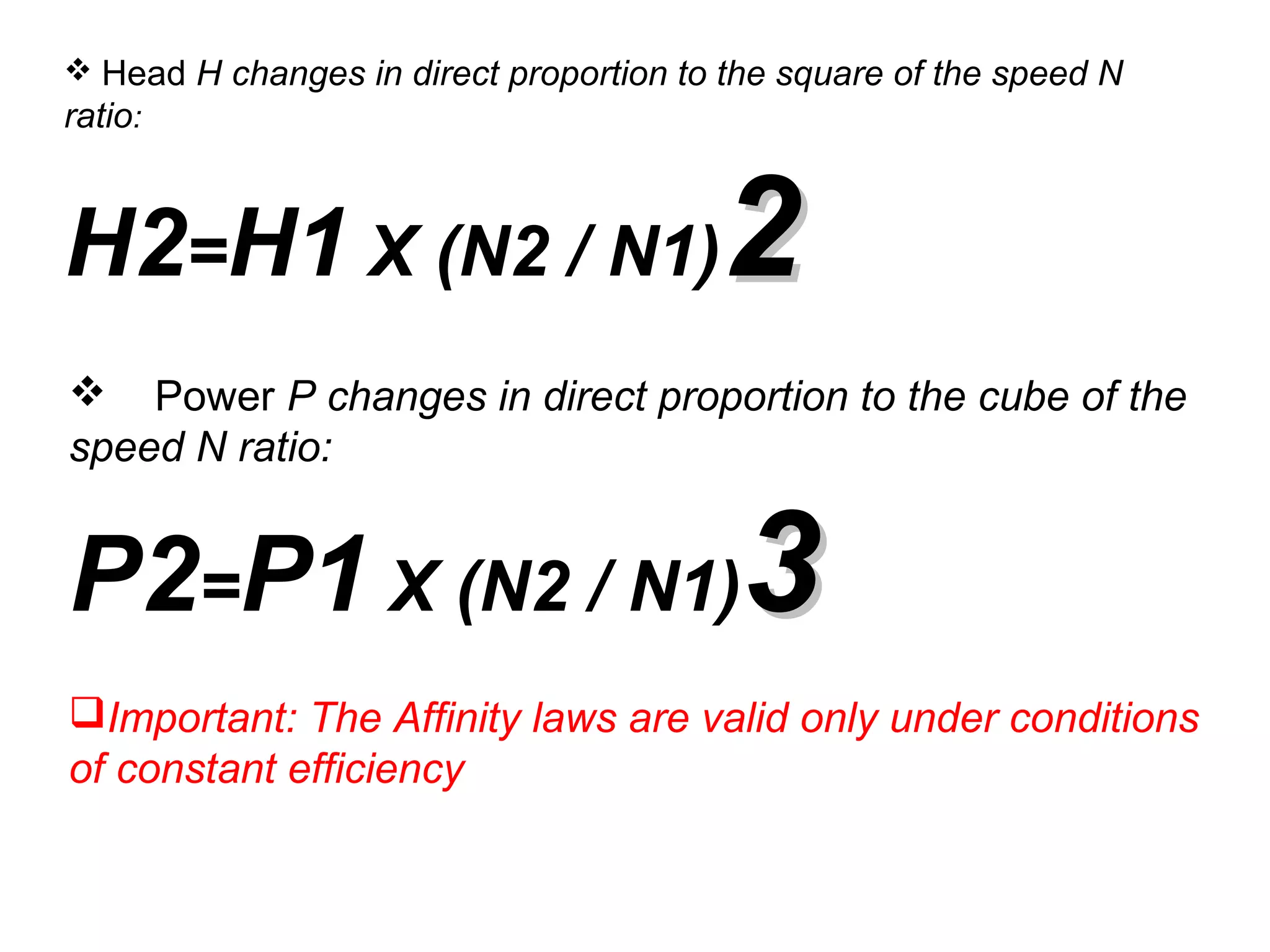
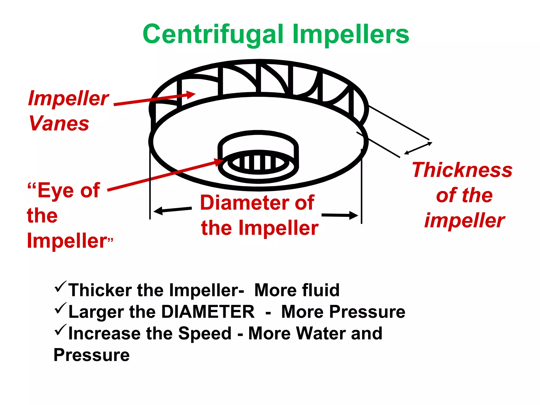
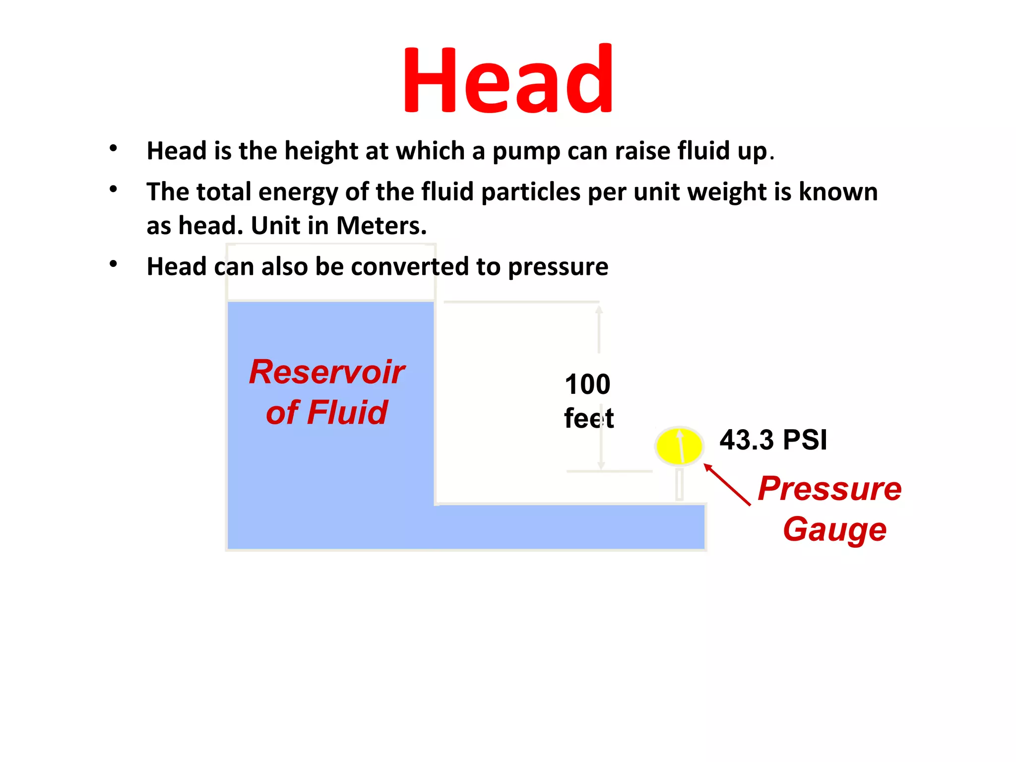
BASIC FUNDAMENTALS OF
CENTRIFUGAL PUMP (By:-Shashi)
CENTRIFUGAL PUMP
• Centrifugal pumps are used for pumping petroleum products like
HSD, SKO, MS,
Naphtha, ATF, LPG etc. in cross country pipelines. Pipeline pumps
are designed as per API 610. The centrifugal pumps are by far the
most commonly used of the pump types. Among all the installed
pumps in a typical petroleum plant, almost 80–90% are centrifugal
pumps.
• Centrifugal pumps are widely used because of their design
simplicity, high efficiency, wide range of capacity, head, smooth
flow rate, and ease of operation and maintenance.
Introduction:
Centrifugal pumps are the rotodynamic machines that
convert mechanical energy of shaft into kinetic and
pressure energy of Fluid which may be used to raise the
level of fluid. A centrifugal pump is named so, because the
energy added by the impeller to the fluid is largely due to
centrifugal effects.
Centrifugal Pumps
PRINCIPAL:-
A machine for moving fluid by accelerating the
fluid RADIALLY outward.
From the Center
of a Circle
RADIAL DIRECTION
To the Outside of a Circle
WORKING MECHANISM OF A CENTRIFUGAL
PUMP
• This machine consists of an IMPELLER rotating
within a case (diffuser)
• Liquid directed into the
center of the rotating
impeller is picked up by
the impeller’s vanes and
accelerated to a higher velocity by the
rotation of the impeller and discharged by
centrifugal force into the case (diffuser).
• Two main components of a centrifugal pump are
the impeller and the casing. The impeller is a
rotating component and the casing is a stationary
component. In centrifugal pump, water enters
axially through the impeller eyes and water exits
radially.
• A collection chamber in the casing converts much of
the Kinetic Energy (energy due to velocity) into
Head or Pressure. This allows centrifugal pumps to
produce continuous flows at high pressure.
Pump
Terminology
Classification of Centrifugal Pumps:-
Centrifugal pumps may be classified according to,
1. Working head
2. Specific speed
3. Type of casing
4. Direction of flow of water
5. Number of entrances to the impeller
6. Disposition of shaft
7. Number of stage
CENTRIFUGAL PUMPS – MAJOR
COMPONENTS:-
The general components of a centrifugal pump, both
stationary and rotary, are shown in
the figures below.
Affinity laws
The ‘Affinity laws’ are mathematical expressions that best define
changes in pump capacity, head, and power absorbed by the
pump when a change is made to pump speed,with all else
remaining constant.
According to affinity laws
 Capacity Q changes in direct proportion to the change in pump speed N ratio:
Q2=Q1 X N2 / N1
 Head H changes in direct proportion to the square of the speed N
ratio:
H2=H1 X (N2 / N1)22
 Power P changes in direct proportion to the cube of the
speed N ratio:
P2=P1 X (N2 / N1)33
Important: The Affinity laws are valid only under conditions
of constant efficiency
Centrifugal Impellers
Impeller
Vanes
“Eye of
the
Impeller”
Thickness
of the
impeller
Diameter of
the Impeller
Thicker the Impeller- More fluid
Larger the DIAMETER - More Pressure
Increase the Speed - More Water and
Pressure
Head• Head is the height at which a pump can raise fluid up.
• The total energy of the fluid particles per unit weight is known
as head. Unit in Meters.
• Head can also be converted to pressure
100
feet
43.3 PSI
Reservoir
of Fluid
Pressure
Gauge
Static Suction Head and Suction
Lift:-
Pump above source;
negative static suction
head, or positive static
suction lift
Pump below source;
static suction head >0
 Any pump raises the liquid from one gradient (head) to another. Thus,
the difference between the discharge head and the suction head is termed
as ‘differential head or total static head.
 Total Head
It is the total head which has to be developed by a pump to deliver the water
form the sump into the tank. Apart from producing the static head, a pump has
also to overcome the losses in pipes and fittings and loss due to kinetic energy
at the delivery outlet.
Let H = Total head
hfs = Losses in suction pipe
hfd = Losses in delivery pipe
hf = Total friction loss in pipe = hfs + hfd
Vd = Velocity of liquid in delivery pipe.
Then H = hs+ hd + hfs + hfd + Vd2
/(2g)
Losses in the casing and the impeller are not taken into account in the total head.
Manometric Head
It is usually not possible to measure exactly the losses in the pump . So, a term
known as manometric head is introduced. It is the rise in pressure energy of the
liquid in the impeller of the pump.
If two pressure gauges are installed on the suction and the delivery sides as near
to the pump as possible, the difference in their reading will give the change in the
pressure energy in the pump or the manometric head.
Hm = Manometric head of the pump
Hms = Reading of the pressure gauge on the suction side
Hmd = Reading of the pressure gauge on the delivery side.
Then Hm = Hmd - Hms
Net Positive Suction Head (NPSH)
• Pumps can pump only liquids, not vapours.
• NPSH is a measure to prevent liquid vaporization.
Net Positive Suction Head or NPSH for pumps can be
defined as the difference between liquid pressure at
pump suction and liquid vapor pressure, expressed in
terms of height of liquid column.
• When vapour pressure is also expressed in terms of
equivalent height of liquid column, and subtracted
from the suction head, the difference is npsh
available at the pump suction.
NPSH is referred to as either required or
available NPSH.
NPSHa = Pressure head + Static suction head -
Vapour pressure head of product – Friction head,loss
in the piping, valves and fittings.
“All terms in feet absolute”
NPSHa should always be greater than NPSHr
Pump Cavitation
What is pump cavitation?
Simply defined, cavitation is the formation of bubbles or cavities in liquid, developed in
areas of relatively low pressure around an impeller. The collapsing of these bubbles
trigger intense shockwaves inside the pump, causing significant damage to the impeller
and/or the pump housing.
If left untreated, pump cavitation can
cause:
1.Failure of pump housing
2.Destruction of impeller
3.Excessive vibration- leading to premature seal and
bearing failure
4.Higher than necessary power consumption
Decreased flow and/or pressure
There are two types of pump cavitation:
suction and discharge.
1.Suction Cavitation:-
When a pump is under low pressure or high vacuum conditions, suction
cavitation occurs. The pump is being "starved" or is not receiving enough
flow. When this happens, bubbles or cavities will form at the eye of the
impeller.
Possible causes of suction cavitation:
1.Clogged filters or strainers
2.Blockage in the pipe
3.Pump is running too far right on the pump curve
4.Poor piping design
5.Poor suction conditions (NPSH requirements)
2. Discharge Cavitation:-
When a pump's discharge pressure is extremely high, or runs at less
than 10% of its best efficiency point (BEP), discharge cavitation occurs.
The high discharge pressure makes it difficult for the fluid to flow out of
the pump, so it circulates inside the pump. Liquid flows between the
impeller and the housing at very high velocity, causing a vacuum at the
housing wall and the formation of bubbles. In extreme, discharge
cavitation can cause the impeller shaft to break.
Possible causes of discharge cavitation:
1.Blockage in the pipe on discharge side
2.Clogged filters or strainers
3.Running too far left on the pump curve
4.Poor piping design
Cavitation Prevention:-
check these things to troubleshoot the problem of cavitation.
1. Check filters and strainers - clogs on the suction, or discharge side
can cause an imbalance of pressure inside the pump
2.Reference the pump's curve - Use a pressure gauge and/or a
flowmeter to understand where your pump is operating on the curve. Make sure
it is running at its best efficiency point
3.Re-evaluate pipe design - Ensure the path the liquid takes to get to
and from your pump is ideal for the pump's operating conditions.
4. To avoid cavitation, always operate with NPSHA ≥ NPSHR.
PUMPS IN SERIES
• Twice the pressure
• Same amount of Fluid.
PUMPS IN SERIES:-
PUMPS IN PARREL:-
• Twice the Flow.
• Same amount of Pressure..
PUMPS IN PARREL:-
Basics Fundamentals and working Principle of Centrifugal Pump.

Basics Fundamentals and working Principle of Centrifugal Pump.

  • 1.
  • 2.
    CENTRIFUGAL PUMP • Centrifugalpumps are used for pumping petroleum products like HSD, SKO, MS, Naphtha, ATF, LPG etc. in cross country pipelines. Pipeline pumps are designed as per API 610. The centrifugal pumps are by far the most commonly used of the pump types. Among all the installed pumps in a typical petroleum plant, almost 80–90% are centrifugal pumps. • Centrifugal pumps are widely used because of their design simplicity, high efficiency, wide range of capacity, head, smooth flow rate, and ease of operation and maintenance.
  • 3.
    Introduction: Centrifugal pumps arethe rotodynamic machines that convert mechanical energy of shaft into kinetic and pressure energy of Fluid which may be used to raise the level of fluid. A centrifugal pump is named so, because the energy added by the impeller to the fluid is largely due to centrifugal effects. Centrifugal Pumps
  • 4.
    PRINCIPAL:- A machine formoving fluid by accelerating the fluid RADIALLY outward. From the Center of a Circle RADIAL DIRECTION To the Outside of a Circle
  • 5.
    WORKING MECHANISM OFA CENTRIFUGAL PUMP • This machine consists of an IMPELLER rotating within a case (diffuser) • Liquid directed into the center of the rotating impeller is picked up by the impeller’s vanes and accelerated to a higher velocity by the rotation of the impeller and discharged by centrifugal force into the case (diffuser).
  • 6.
    • Two maincomponents of a centrifugal pump are the impeller and the casing. The impeller is a rotating component and the casing is a stationary component. In centrifugal pump, water enters axially through the impeller eyes and water exits radially. • A collection chamber in the casing converts much of the Kinetic Energy (energy due to velocity) into Head or Pressure. This allows centrifugal pumps to produce continuous flows at high pressure.
  • 7.
  • 8.
    Classification of CentrifugalPumps:- Centrifugal pumps may be classified according to, 1. Working head 2. Specific speed 3. Type of casing 4. Direction of flow of water 5. Number of entrances to the impeller 6. Disposition of shaft 7. Number of stage
  • 9.
    CENTRIFUGAL PUMPS –MAJOR COMPONENTS:-
  • 10.
    The general componentsof a centrifugal pump, both stationary and rotary, are shown in the figures below.
  • 19.
    Affinity laws The ‘Affinitylaws’ are mathematical expressions that best define changes in pump capacity, head, and power absorbed by the pump when a change is made to pump speed,with all else remaining constant. According to affinity laws  Capacity Q changes in direct proportion to the change in pump speed N ratio: Q2=Q1 X N2 / N1
  • 20.
     Head Hchanges in direct proportion to the square of the speed N ratio: H2=H1 X (N2 / N1)22  Power P changes in direct proportion to the cube of the speed N ratio: P2=P1 X (N2 / N1)33 Important: The Affinity laws are valid only under conditions of constant efficiency
  • 21.
    Centrifugal Impellers Impeller Vanes “Eye of the Impeller” Thickness ofthe impeller Diameter of the Impeller Thicker the Impeller- More fluid Larger the DIAMETER - More Pressure Increase the Speed - More Water and Pressure
  • 22.
    Head• Head isthe height at which a pump can raise fluid up. • The total energy of the fluid particles per unit weight is known as head. Unit in Meters. • Head can also be converted to pressure 100 feet 43.3 PSI Reservoir of Fluid Pressure Gauge
  • 23.
    Static Suction Headand Suction Lift:- Pump above source; negative static suction head, or positive static suction lift Pump below source; static suction head >0
  • 24.
     Any pumpraises the liquid from one gradient (head) to another. Thus, the difference between the discharge head and the suction head is termed as ‘differential head or total static head.  Total Head It is the total head which has to be developed by a pump to deliver the water form the sump into the tank. Apart from producing the static head, a pump has also to overcome the losses in pipes and fittings and loss due to kinetic energy at the delivery outlet. Let H = Total head hfs = Losses in suction pipe hfd = Losses in delivery pipe hf = Total friction loss in pipe = hfs + hfd Vd = Velocity of liquid in delivery pipe. Then H = hs+ hd + hfs + hfd + Vd2 /(2g) Losses in the casing and the impeller are not taken into account in the total head.
  • 27.
    Manometric Head It isusually not possible to measure exactly the losses in the pump . So, a term known as manometric head is introduced. It is the rise in pressure energy of the liquid in the impeller of the pump. If two pressure gauges are installed on the suction and the delivery sides as near to the pump as possible, the difference in their reading will give the change in the pressure energy in the pump or the manometric head. Hm = Manometric head of the pump Hms = Reading of the pressure gauge on the suction side Hmd = Reading of the pressure gauge on the delivery side. Then Hm = Hmd - Hms
  • 28.
    Net Positive SuctionHead (NPSH) • Pumps can pump only liquids, not vapours. • NPSH is a measure to prevent liquid vaporization. Net Positive Suction Head or NPSH for pumps can be defined as the difference between liquid pressure at pump suction and liquid vapor pressure, expressed in terms of height of liquid column. • When vapour pressure is also expressed in terms of equivalent height of liquid column, and subtracted from the suction head, the difference is npsh available at the pump suction.
  • 30.
    NPSH is referredto as either required or available NPSH. NPSHa = Pressure head + Static suction head - Vapour pressure head of product – Friction head,loss in the piping, valves and fittings. “All terms in feet absolute” NPSHa should always be greater than NPSHr
  • 31.
  • 33.
    What is pumpcavitation? Simply defined, cavitation is the formation of bubbles or cavities in liquid, developed in areas of relatively low pressure around an impeller. The collapsing of these bubbles trigger intense shockwaves inside the pump, causing significant damage to the impeller and/or the pump housing. If left untreated, pump cavitation can cause: 1.Failure of pump housing 2.Destruction of impeller 3.Excessive vibration- leading to premature seal and bearing failure 4.Higher than necessary power consumption Decreased flow and/or pressure
  • 34.
    There are twotypes of pump cavitation: suction and discharge. 1.Suction Cavitation:- When a pump is under low pressure or high vacuum conditions, suction cavitation occurs. The pump is being "starved" or is not receiving enough flow. When this happens, bubbles or cavities will form at the eye of the impeller. Possible causes of suction cavitation: 1.Clogged filters or strainers 2.Blockage in the pipe 3.Pump is running too far right on the pump curve 4.Poor piping design 5.Poor suction conditions (NPSH requirements)
  • 35.
    2. Discharge Cavitation:- Whena pump's discharge pressure is extremely high, or runs at less than 10% of its best efficiency point (BEP), discharge cavitation occurs. The high discharge pressure makes it difficult for the fluid to flow out of the pump, so it circulates inside the pump. Liquid flows between the impeller and the housing at very high velocity, causing a vacuum at the housing wall and the formation of bubbles. In extreme, discharge cavitation can cause the impeller shaft to break. Possible causes of discharge cavitation: 1.Blockage in the pipe on discharge side 2.Clogged filters or strainers 3.Running too far left on the pump curve 4.Poor piping design
  • 36.
    Cavitation Prevention:- check thesethings to troubleshoot the problem of cavitation. 1. Check filters and strainers - clogs on the suction, or discharge side can cause an imbalance of pressure inside the pump 2.Reference the pump's curve - Use a pressure gauge and/or a flowmeter to understand where your pump is operating on the curve. Make sure it is running at its best efficiency point 3.Re-evaluate pipe design - Ensure the path the liquid takes to get to and from your pump is ideal for the pump's operating conditions. 4. To avoid cavitation, always operate with NPSHA ≥ NPSHR.
  • 37.
    PUMPS IN SERIES •Twice the pressure • Same amount of Fluid.
  • 38.
  • 39.
    PUMPS IN PARREL:- •Twice the Flow. • Same amount of Pressure..
  • 40.