Downloaded 107 times
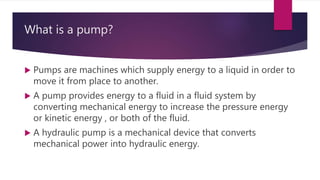
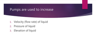
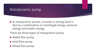
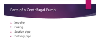
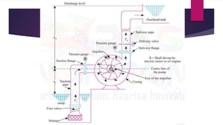
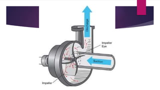


The document provides a comprehensive overview of centrifugal pumps, explaining their function as machines that supply energy to liquids to facilitate movement. It categorizes pumps into rotodynamic and positive displacement types and details the construction and working principles of centrifugal pumps, including parts such as impellers and casings. Additionally, it outlines advantages and disadvantages along with various applications in agriculture and building water systems.


![SBP- Centrifugal and recoprocating pump [Compatibility Mode].pdf](https://cdn.slidesharecdn.com/ss_thumbnails/sbp-centrifugalandrecoprocatingpumpcompatibilitymode-241227102119-6ae861f2-thumbnail.jpg?width=640&height=640&fit=bounds)


