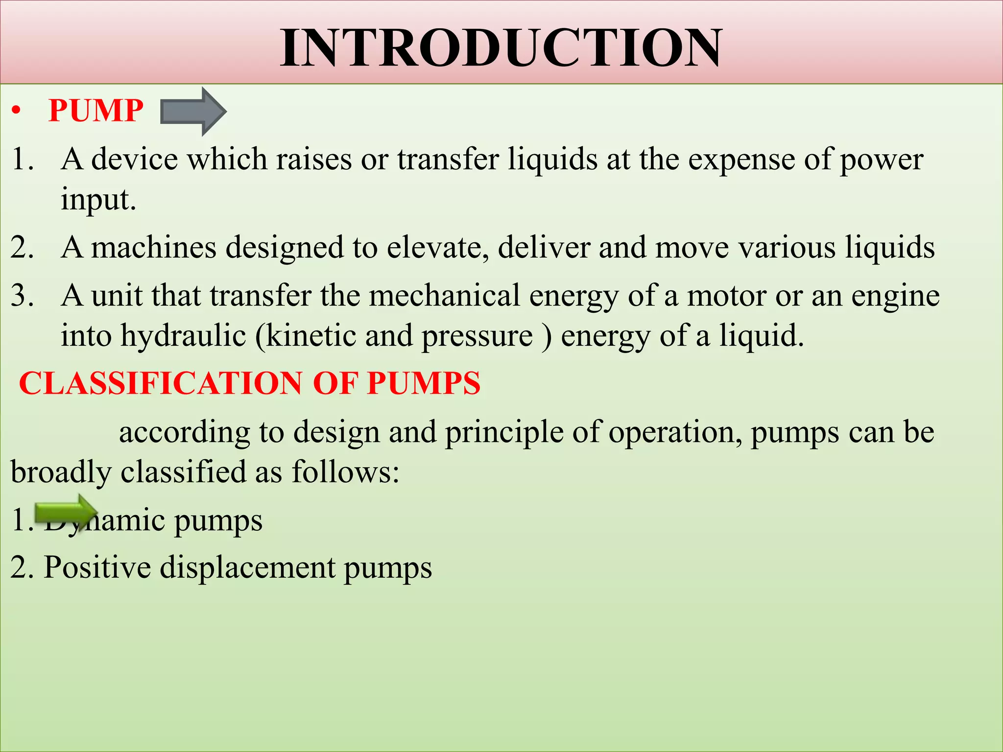
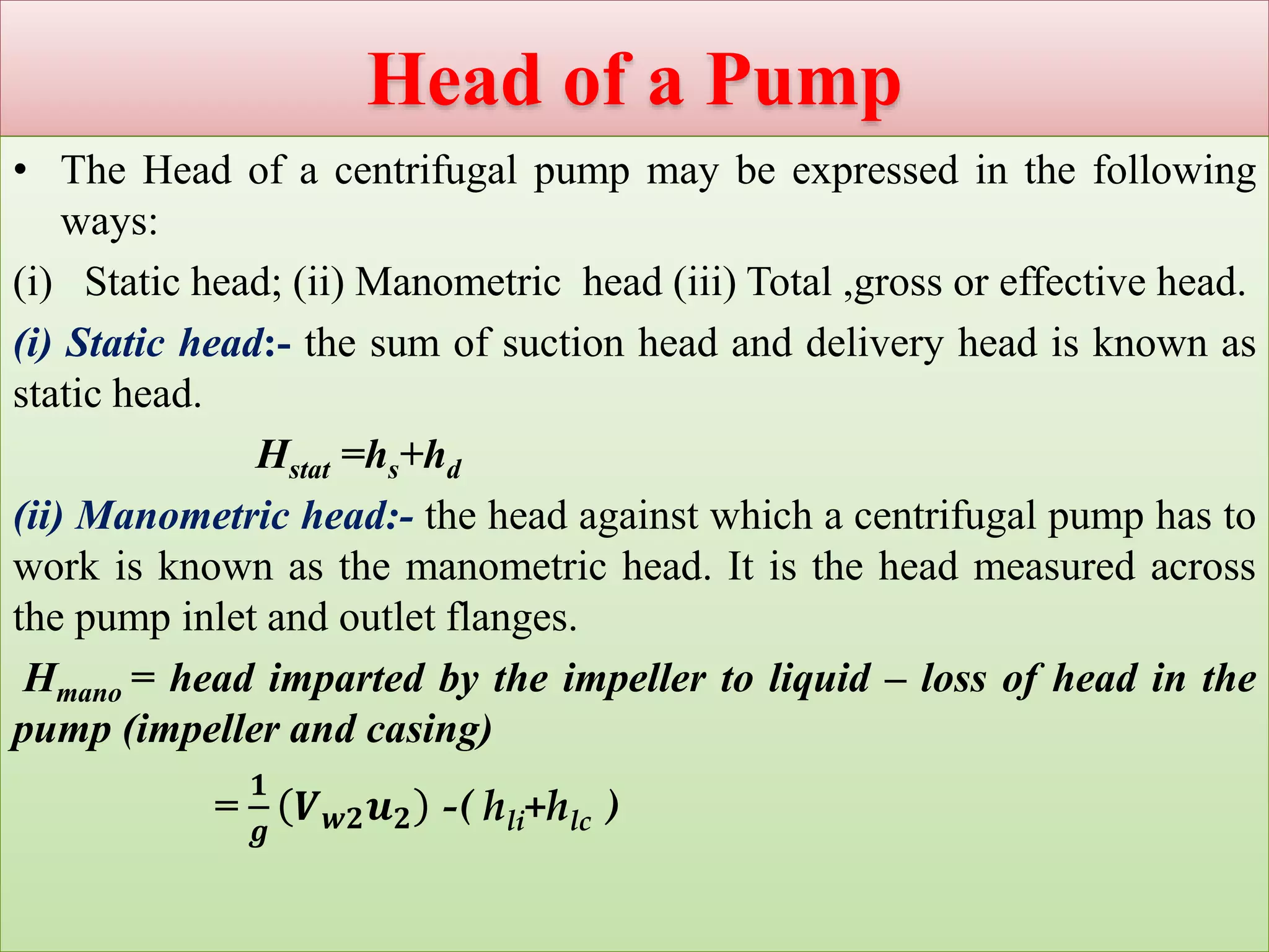
This document provides an overview of centrifugal pumps. It defines a pump and discusses the main components and classifications of centrifugal pumps. The key components of a centrifugal pump are the impeller, casing, suction pipe, and delivery pipe. Centrifugal pumps are classified based on impeller design and casing shape. The document also covers topics such as work done by the centrifugal pump, head of a pump, losses and efficiencies, and minimum speed for starting a centrifugal pump. Several example problems are provided to calculate values like inlet vane angle, work done, and minimum starting speed.
This Presentation is about working principle of Pumps.Basic Presentation regarding pumps , will definitely help beginners to learn pump types , their working , their parts etc.
the presentation includes basic ideas about water pumps, various terminology generally used for the pumps, classification of pumps and ideas about the types its construction and working
Minor losses are a major part in calculating the flow, pressure, or energy reduction in piping systems. Liquid moving through pipes carries momentum and energy due to the forces acting upon it such as pressure and gravity. Just as certain aspects of the system can increase the fluids energy, there are components of the system that act against the fluid and reduce its energy, velocity, or momentum. Friction and minor losses in pipes are major contributing factors.
In this report , I shall shade the light on the two types :
1- Reciprocating positive displacement pumps .
2- Centrifugal dynamic pumps.
The comparison will include the following points for each type :
1- Working principle.
2- Usage.
3- Efficiency
4- Connection Methods (in series and in parallel )
Pump and pumps classification.Introduction of Pumps.Applications of Pumps.Types of pump.Centrifugal Pump. Diaphragm pump.lobe pump.Positive displacement pump
Gear pump. Uses of pump.
Basics Fundamentals and working Principle of Centrifugal Pump.SHASHI BHUSHAN
Basics Fundamentals and working Principle of Centrifugal Pump. Centrifugal pumps are the rotodynamic machines that convert mechanical energy of shaft into kinetic and pressure energy of Fluid which may be used to raise the level of fluid. A centrifugal pump is named so, because the energy added by the impeller to the fluid is largely due to centrifugal effects.
This article helps you understand the term NPSH, how it is calculated and its importance when selecting a centrifugal pump. This basic knowledge of NPSH will help you go a long way in identifying potential problems in your pump even before they occur.
Centrifugal pumps are machines which use centrifugal force to move liquids. In this program, you will learn the principles, parts, and general operation of these pumps, what pump efficiency is, and how head and pressure are calculated.
Positive displacement pumps are reciprocating and rotary pumps that move liquid by the positive displacement of liquid volume. In this presentation, you will learn the operating principles and performance characteristics of positive displacement pumps, what determines their capacity, pressure, horsepower and efficiency, and how NPSH is calculated. You will also learn the basic types of reciprocating and rotary pumps, including piston pumps, plunger pumps, diaphragm pumps, direct-acting steam and air pumps, and rotary lobe, vane, gear and screw pumps, and how these pumps differ from each other in design and performance.
The pdf contains explanation about the centrifugal pumps. It is usually studied by Mechanical or Civil engineering students. This pdf file will help for the students from these fields.
Modal 05: Question Number 9 a & 9 b
Centrifugal Pumps:
i. Classification and parts of centrifugal pump,
ii. Different heads of centrifugal pump
iii. Different efficiencies of centrifugal pump,
iv. Theoretical head – capacity relationship,
v. Minimum speed for starting the flow,
vi. Maximum suction lift,
vii. Net positive suction head,
viii. Cavitation,
ix. Need for priming,
x. Pumps in series and parallel. Problems.
Previous Year Question papers
NO1 Uk best vashikaran specialist in delhi vashikaran baba near me online vas...Amil Baba Dawood bangali
Contact with Dawood Bhai Just call on +92322-6382012 and we'll help you. We'll solve all your problems within 12 to 24 hours and with 101% guarantee and with astrology systematic. If you want to take any personal or professional advice then also you can call us on +92322-6382012 , ONLINE LOVE PROBLEM & Other all types of Daily Life Problem's.Then CALL or WHATSAPP us on +92322-6382012 and Get all these problems solutions here by Amil Baba DAWOOD BANGALI
#vashikaranspecialist #astrologer #palmistry #amliyaat #taweez #manpasandshadi #horoscope #spiritual #lovelife #lovespell #marriagespell#aamilbabainpakistan #amilbabainkarachi #powerfullblackmagicspell #kalajadumantarspecialist #realamilbaba #AmilbabainPakistan #astrologerincanada #astrologerindubai #lovespellsmaster #kalajaduspecialist #lovespellsthatwork #aamilbabainlahore#blackmagicformarriage #aamilbaba #kalajadu #kalailam #taweez #wazifaexpert #jadumantar #vashikaranspecialist #astrologer #palmistry #amliyaat #taweez #manpasandshadi #horoscope #spiritual #lovelife #lovespell #marriagespell#aamilbabainpakistan #amilbabainkarachi #powerfullblackmagicspell #kalajadumantarspecialist #realamilbaba #AmilbabainPakistan #astrologerincanada #astrologerindubai #lovespellsmaster #kalajaduspecialist #lovespellsthatwork #aamilbabainlahore #blackmagicforlove #blackmagicformarriage #aamilbaba #kalajadu #kalailam #taweez #wazifaexpert #jadumantar #vashikaranspecialist #astrologer #palmistry #amliyaat #taweez #manpasandshadi #horoscope #spiritual #lovelife #lovespell #marriagespell#aamilbabainpakistan #amilbabainkarachi #powerfullblackmagicspell #kalajadumantarspecialist #realamilbaba #AmilbabainPakistan #astrologerincanada #astrologerindubai #lovespellsmaster #kalajaduspecialist #lovespellsthatwork #aamilbabainlahore #Amilbabainuk #amilbabainspain #amilbabaindubai #Amilbabainnorway #amilbabainkrachi #amilbabainlahore #amilbabaingujranwalan #amilbabainislamabad
CFD Simulation of By-pass Flow in a HRSG module by R&R Consult.pptxR&R Consult
CFD analysis is incredibly effective at solving mysteries and improving the performance of complex systems!
Here's a great example: At a large natural gas-fired power plant, where they use waste heat to generate steam and energy, they were puzzled that their boiler wasn't producing as much steam as expected.
R&R and Tetra Engineering Group Inc. were asked to solve the issue with reduced steam production.
An inspection had shown that a significant amount of hot flue gas was bypassing the boiler tubes, where the heat was supposed to be transferred.
R&R Consult conducted a CFD analysis, which revealed that 6.3% of the flue gas was bypassing the boiler tubes without transferring heat. The analysis also showed that the flue gas was instead being directed along the sides of the boiler and between the modules that were supposed to capture the heat. This was the cause of the reduced performance.
Based on our results, Tetra Engineering installed covering plates to reduce the bypass flow. This improved the boiler's performance and increased electricity production.
It is always satisfying when we can help solve complex challenges like this. Do your systems also need a check-up or optimization? Give us a call!
Work done in cooperation with James Malloy and David Moelling from Tetra Engineering.
More examples of our work https://www.r-r-consult.dk/en/cases-en/
Water scarcity is the lack of fresh water resources to meet the standard water demand. There are two type of water scarcity. One is physical. The other is economic water scarcity.
Immunizing Image Classifiers Against Localized Adversary Attacksgerogepatton
This paper addresses the vulnerability of deep learning models, particularly convolutional neural networks
(CNN)s, to adversarial attacks and presents a proactive training technique designed to counter them. We
introduce a novel volumization algorithm, which transforms 2D images into 3D volumetric representations.
When combined with 3D convolution and deep curriculum learning optimization (CLO), itsignificantly improves
the immunity of models against localized universal attacks by up to 40%. We evaluate our proposed approach
using contemporary CNN architectures and the modified Canadian Institute for Advanced Research (CIFAR-10
and CIFAR-100) and ImageNet Large Scale Visual Recognition Challenge (ILSVRC12) datasets, showcasing
accuracy improvements over previous techniques. The results indicate that the combination of the volumetric
input and curriculum learning holds significant promise for mitigating adversarial attacks without necessitating
adversary training.
Hierarchical Digital Twin of a Naval Power SystemKerry Sado
A hierarchical digital twin of a Naval DC power system has been developed and experimentally verified. Similar to other state-of-the-art digital twins, this technology creates a digital replica of the physical system executed in real-time or faster, which can modify hardware controls. However, its advantage stems from distributing computational efforts by utilizing a hierarchical structure composed of lower-level digital twin blocks and a higher-level system digital twin. Each digital twin block is associated with a physical subsystem of the hardware and communicates with a singular system digital twin, which creates a system-level response. By extracting information from each level of the hierarchy, power system controls of the hardware were reconfigured autonomously. This hierarchical digital twin development offers several advantages over other digital twins, particularly in the field of naval power systems. The hierarchical structure allows for greater computational efficiency and scalability while the ability to autonomously reconfigure hardware controls offers increased flexibility and responsiveness. The hierarchical decomposition and models utilized were well aligned with the physical twin, as indicated by the maximum deviations between the developed digital twin hierarchy and the hardware.
Saudi Arabia stands as a titan in the global energy landscape, renowned for its abundant oil and gas resources. It's the largest exporter of petroleum and holds some of the world's most significant reserves. Let's delve into the top 10 oil and gas projects shaping Saudi Arabia's energy future in 2024.
2. INTRODUCTION
• PUMP
1. A device which raises or transfer liquids at the expense of power
input.
2. A machines designed to elevate, deliver and move various liquids
3. A unit that transfer the mechanical energy of a motor or an engine
into hydraulic (kinetic and pressure ) energy of a liquid.
CLASSIFICATION OF PUMPS
according to design and principle of operation, pumps can be
broadly classified as follows:
1. Dynamic pumps
2. Positive displacement pumps
3. CENTRIFUGAL PUMPS
Centrifugal pumps belong to the category of dynamic pressure pumps
wherein the pumping of liquid or generation of head is affected by
rotary motion of one or more rotating wheels called the impellers.
A centrifugal pump consists of the following main parts:
i. Impeller
ii. Casing
iii. Suction pipe
iv. Delivery pipe.
Impeller:- an impeller is a wheel (or rotor) with a series of backward
curved vanes(blades). It is mounted on a shaft which is usually
coupled with electric motor or an internal combustion engine.by virtue
of force interaction between the vanes and the liquid, the mechanical
energy of the driver is transmitted into the energy of the flow.
4.
5. Casing:-
The casing is an airtight chamber surrounding the pump impeller. It
contain suction and discharge arrangements, supporting for bearings and
facilitates to house the rotor assembly. It has provision to fix stuffing box
and house packing materials which prevent external leakage.
Purpose of the casing are:
1. To guide water to and from the impeller,
2. To partially convert the kinetic energy into pressure energy
6. Suction pipe:-
The pipe which connects the centre/eye of the impeller to sump
from which liquid is to be lifted is known as suction pipe. The pipe is
laid airtight so that there is no possibilities of formation of air pockets.
Suction pipe is provided with a strainer at its lower ends to prevent the
entry of solid particles, debries etc. into the pump. The lower end of the
pipe is also fitted with a non-return foot valve which does not permit the
liquid to drain out of the suction pipe when pump is not working ; this
also helps in priming.
Delivery pipe:-
The pipe which is connected at outlet of the pump and delivers the
liquid to the required height is known as delivery pipe. A regulating
valve is provided on the delivery pipe to regulate the supply flow of
liquid.
7. Classification of centrifugal pumps
Shape and Type of Casing:-
1. volute or diffuser cfp
2. vortex type cfp.
3. volute casing with guided blades cfp.
8. Based on impeller design
1. Shrouded or closed impeller
2. Open impeller
3. Semi- open impeller
9. Work done by the Centrifugal Pump
• The expression for work done or energy supplied by the impeller of a
centrifugal pump on the liquid flowing through the pump. The liquid
enters the impeller at its centre and leaves at its outer periphery.
Assumption
i. Liquid enters the impeller eye in radial direction, the whirl
component Vwl (of the inlet absolute velocity V1) is zero and the
flow component Vf1 =V1, α=90 degree.
ii. No energy loss in the impeller due to friction and eddy formation.
iii. No loss due to shock at entry.
iv. There is a uniform velocity distribution in the narrow passage
formed between two adjacent vanes.
10.
11. • Let , D1 = diametNer of the impeller at the inlet
N = speed of the impeller in r.p.m.,
ω = angular velocity (=
2𝜋𝑁
60
𝑟𝑎𝑑/𝑠)
u1 = tangential velocity of the impeller at inlet
=
𝜋𝐷1 𝑁
60
=
2𝜋𝑅1 𝑁
60
= ω𝑅1
D2= diameter of the impellet at outlet
𝑢2= tangential velocity of impeller at outlet
=
𝜋𝐷2 𝑁
60
=
2𝜋𝑅2 𝑁
60
= ω𝑅2
V1=absolute velocity of water at inlet
𝑉 𝑤1= velocity of whirl at inlet
𝑉𝑟1 = relative velocity of liquid at inlet
𝑉𝑓1 = velocity of flow at inlet
α = angle made by absolute velocity at inlet
with the direction of motion of vane.
12. θ = angle made by the relative velocity at inlet with the direction
of motion of vane, and
𝑉2,𝑉 𝑤2,𝑉𝑟2,𝑉𝑓2,β and φ are the corresponding values at outlet.
while passing through the impeller, the velocity of whirl changes
and there is change of momentum of momentum.
Change of angular momentum is given by:
=𝑚 𝑉 𝑤2 𝑟2 − 𝑉 𝑤1 𝑟1
=𝜌𝑄 𝑉 𝑤2 𝑟2 − 𝑉 𝑤1 𝑟1 =
𝑤𝑄
𝑔
𝑉 𝑤2 𝑟2 − 𝑉 𝑤1 𝑟1
where Q is the volume of liquid entering and leaving the impeller
in a unit time,
From the momentum theorem , the change of angular
momentum equals the torque exerted by the impeller on the
liquid.
Torque =
𝑤𝑄
𝑔
𝑉 𝑤2 𝑟2 − 𝑉 𝑤1 𝑟1
13. • Now energy transfer = torque × rotational speed in rad/s
𝐸 =
𝑤𝑄
𝑔
𝑉 𝑤2 𝑟2 − 𝑉 𝑤1 𝑟1 × 𝜔 =
𝑤𝑄
𝑔
𝑉 𝑤2 𝑢2 − 𝑉 𝑤1 𝑢1
The energy transfer per unit weight is referred to as Euler head,
He.
𝐻𝑒 =
𝐸
𝑤𝑄
=
1
𝑔
𝑉 𝑤2 𝑢2 − 𝑉 𝑤1 𝑢1 …………………(a)
Euler momentum equation.
for an axial or radial fluid entry(fluid entering the impeller has no
whirl component).
𝐻𝑒 =
𝐸
𝑤𝑄
=
1
𝑔
𝑉 𝑤2 𝑢2 ………………(b)
here Q = A1 𝑉𝑓1= 𝐴2 𝑉𝑓2
= 𝜋𝐷1 𝐵1 𝑉𝑓1= 𝜋𝐷2 𝐵2 𝑉𝑓2
equation (b) stipulates that for delivering high heads the peripheral
velocity u2 must be high and the vector 𝑉 𝑤2 must be large enough.
14. • From outlet velocity triangle, we have
or …….(i)
……………(ii)
From (i) and (ii)
similarly from inlet triangle, we can obtain:
Work done per second per unit weight of liquid
=
22 2
2 2 2 2
2 2 2
2 2 2
r f w
f w
V V u V
V V V
22 2
2 2 2 2f r wV V u V
2 2 2
2 2 2
2 2
2
r
w
V u V
u V
2 2 2
1 1 1
1 1
2
r
w
V u V
u V
2 2 2 2 2 2
2 1 2 1 1 2
2 2 2
r rV V u u V V
g g g
15. Q.1 The impeller of a centrifugal pump has an external diameter of
450 mm and internal diameter of 200mm and it runs at 1440 r.p.m.
assuming a constant radial flow throughout the impeller at 2.5 m/s
and that the vanes at exit are set back at an angle 25 , determine
i) Inlet vane angle,
ii) The angle, absolute velocity of water at exit makes with the
tangent
iii) The work done per N of water
16. Head of a Pump
• The Head of a centrifugal pump may be expressed in the following
ways:
(i) Static head; (ii) Manometric head (iii) Total ,gross or effective head.
(i) Static head:- the sum of suction head and delivery head is known as
static head.
Hstat =hs+hd
(ii) Manometric head:- the head against which a centrifugal pump has to
work is known as the manometric head. It is the head measured across
the pump inlet and outlet flanges.
Hmano = head imparted by the impeller to liquid – loss of head in the
pump (impeller and casing)
=
𝟏
𝒈
𝑽 𝒘𝟐 𝒖 𝟐 -( hli+hlc )
17. (iii) Total , gross or effective head:- it is equal to the static head
plus all the head losses occurring in flow before , through and
after the impeller.
Losses and Efficiencies of a centrifugal pump
Losses in cfp :-
1. Hydraulic losses:-
a. Shock or eddy losses at the entrance to and exit from the impeller.
b. Losses due to friction in the impeller.
c. Friction and eddy losses in the guide vanes/diffuser and casing.
2. Mechanical losses:-
a. Losses due to disc friction between the impeller and the liquid which
fills the clearance spaces between the impeller and casing.
b. Losses pertaining to friction of the main bearing and glands.
18. Efficiencies of a centrifugal Pump
i. Manometric efficiency(ηmano): The ratio of the manometric head
developed by the pump to the head imparted by the impeller to the
liquid is known as manometric efficiency.
ii. Volumetric efficiency(ηv): the ratio of quantity of liquid discharged
per second from the pump to quantity passing per second through the
impeller is known as volumetric efficiency.
Q= Actual liquid discharged per seconds at the pump outlet
q= Leakage of liquid per second from the impeller (through the
clearance between the impeller and casing).
2 22 2
mano mano
mano
wW
H gH
V uV u
g
ηv =
𝑄
𝑄+𝑞
19. iii. Mechanical efficiency(ηm):- The ratio of the power delivered by the
impeller to the liquid to the power input to the pump shaft is known as
mechanical efficiency.
iv. Overall efficiency(ηo):- The ratio of power output of the pump to the
power input to the pump is known as overall efficiency.
2 2w
m
V u
w Q q
g
P
mano
o
o mano v m
wQH
P
20. Q.1 A centrifugal pump is to discharge 0.118 m3/s at speed of 1450 r.p.m
against a head of 25m. The impeller diameter is 250mm, its width at
outlet is 50mm and manometric efficiency is 75%. Determine the vane
angle at the outer periphery of the impeller.
Q.2 The impeller of a centrifugal pump having external and internal
diameters 500mm and 250mm respectively, width at outlet 50mm and
running at 1200 r.p.m. work against a head of 48m. The velocity of flow
through the impeller is constant and equal to 3m/s. the vanes are set back
at an angle of 40 degree at outlet. Determine :
i. Inlet vane angle
ii. Work done by the impeller on water per second
iii. Manometric efficiency.
21. Minimum speed for starting a centrifugal
pump
• When a centrifugal pump is started, it will start delivering liquid only
if the pressure rise in the impeller is more than or equal to the
manometric head.
=
• Flow will commence only if ≥Hmano
• For minimum speed ,we must have
= Hmano ……………(1)
also ,
2 2 2 2 2 2
2 1 2 1 1 2
2 2 2
r rV V u u V V
g g g
2 2
2 1
2
u u
g
2 2
2 1
2
u u
g
2 2
2 1
2
u u
g
2 22 2
mano mano
mano
wW
H gH
V uV u
g
22. • Substitute the value in eqn. 1
2 2
1
1
60
w
mano mano
V u
H
g
D N
u
2
2
60
D N
u
2 2
22 1 21
2 60 60 60
w
mano
VD N D N D N
g g
2 2
2 1 2 2
120
mano w
N
D D V D
2 2
min 2 2
2 1
120 mano wV D
N
D D
23. Q.1 A centrifugal pump working in a dock pump 1565 litres per second
against a mean lift of 6.1m when the impeller rotates at 200 r.p.m. the
impeller diameter is 1.22 m and area at outer periphery is 6450 cm2. if
the vanes are set back at an angle of 26 degree at the outlet, determine:
i. Manometric(hydraulic ) efficiency
ii. Power required to drive the pump
iii. Minimum speed to start pumping if the ratio of external to internal
diameter is 2.
24. Slip in Centrifugal Pump
• Due to inertial effects, the liquid which is trapped between the
impeller vanes is reluctant to move round with the impeller. This
results in a difference of pressure force across the vanes; there being a
high pressure on the leading surface and low pressure on the trailing
surface. This difference of pressure is known as vane loading and it
increases with an increase in the number of vanes.
• Because of pressure variation, a velocity gradient exist across the
channel.
• On the high pressure side (leading surface) liquid follows the blade
contour; it leaves the blade tangentially.
• On the low pressure side, the liquid leaves the vanes with a certain
circumferential component. The liquid will thus discharged at a
certain average angle β2’ which is less than the geometric blade angle
β2 .
25. • Due to deviation in the flow path, the tangential components get
reduced from 𝑉 𝑤2 to 𝑉 𝑤2 ’.
• The difference or deviation (𝑉 𝑤2 - 𝑉 𝑤2 ’)is called slip of the impeller.
• The slip coefficient is then defined as = '
2
2
w
w
V
V
26. Effect of variation of Liquid Flow rate on the
Head
• When pump operates and discharges the liquid at its designed speed,
the efficiency is maximum. If there is variation in flow rate , its
efficiency reduced due to shocks occurs at entrance to the impeller,
resulting loss of head.
1. When discharge is decreases , the flow velocity decreases Vf1 to Vf1‘.
If the tangential velocity is constant(pump running at same speed)
then u1 unchanged. In the new velocity triangle, new relative velocity
component is not follow the path(contour) of vane with angle β1 .
Therefore shock occurs at entry to impeller. But when the Vf1‘ is
fixed and flow taking place along the vane, then it sudden decreases
the tangential velocity brings about shock and resulting there is loss
of head.
27. Q.1 A centrifugal pump has an impeller of 100cm in diameter(external)
and it delivers 1200 lit/s against a head of 100m. The impeller runs at
980 rpm and width at outlet is 8.5 cm. if leakage loss is 3% of discharge ,
external mechanical loss is 9 kw and the hydraulic efficiency is 79%.
Calculate
1. Blade angle at outlet
2. The power required to drive the pump
3. Overall efficiency of the pump.
28. Design consideration of Centrifugal Pumps
1. Speed ratio: it is the ratio of peripheral speed at exit (u2) to the
theoretical velocity of jet corresponding to manometric head(Hmano).
; varies from 0.95 to 1.25
2. Flow ratio: it is the ratio of the velocity of flow at exit to the
theoretical velocity of the jet corresponding to manometric
head(Hmano ).
; varies from 0.1 to 0.25
2
2
u
mano
u
K
gH
uK
2
2
f
f
mano
V
K
gH
fK
29. Specific speed
• The specific speed of a centrifugal pump is defined as the speed of a
geometrically similar pump which would deliver unit quantity( one
cubic meter of liquid per second) against a unit head ( one meter). It is
denoted by Ns. The specific speed is a characteristic of a pumps which
can be used as a basis for comparing the performance of different
pumps.
The discharge through impeller is given by=area×velocity of flow
𝑄 = 𝜋𝐷1 𝐵1 𝑉𝑓1=𝜋𝐷2 𝐵2 𝑉𝑓2
𝑄 ∝ 𝐷𝐵𝑉𝑓 , 𝑄 ∝ 𝐷2 𝑉𝑓 ( 𝐵 ∝ 𝐷)……………..(i)
The tangential speed of impeller is given by
𝑢 =
𝜋𝐷𝑁
60
𝑢 ∝ 𝐷𝑁 ……………..(ii)
but 𝑢 = 𝐾 𝑢 2𝑔𝐻 𝑚 𝑢 ∝ 𝐻 𝑚 ………....(iii)
Q
30. and 𝑉𝑓=𝐾𝑓 2𝑔𝐻 𝑚 𝑉𝑓 ∝ 𝐻 𝑚 ……………(iv)
From eqn. (ii) and (iii) we get
𝐷𝑁 ∝ 𝐻 𝑚 𝐷 ∝
𝐻 𝑚
𝑁
………………..(v)
Putting eqn. (iv) and (v) in eqn. (i)
𝑄 ∝
𝐻 𝑚
𝑁
2
𝐻 𝑚 𝑄 ∝
𝐻 𝑚
3
2
𝑁2 𝑁2
∝
𝐻 𝑚
3/2
𝑄
𝑁 = 𝐶
𝐻 𝑚
3/4
𝑄
where C is constant.
When Q=1m3/s, Hm= 1m then C=N which is known as specific speed Ns
𝑁𝑠=
𝑁 𝑄
𝐻 𝑚
3/4
31. Q.1 A multi-stage boiler feed pump is required to pump 115×10^3 kg of
water per hour against a pressure difference of 3150 kN/m2. when
running at a speed of 3000rpm. The density of preheated feed water is
950 kg/m3. if all the impeller are identical and the specific speed per
stage is not to be less than 22, calculate
1. The least number of stages and head developed per stage
2. The diameter of the impeller
3. The shaft power required to drive the pump . It may be assumed that
overall efficiency is 77% and peripheral velocity of impeller is given
by 𝑢 = 0.96 2𝑔𝐻 𝑚 , where Hm is the head per stage.
32. Maximum suction lift or suction height
consider a centrifugal pump which lifts a liquid from a sump. The
free surface of liquid is at depth of hs below the centre of impeller.
Applying energy eqn. at free surface
of liquid and inlet of impeller.
2 2
1 1
1
2 2
atm atm
atm fs
p V p V
z z h
g g g g
2
1
2
atm s
s fs
p Vp
h h
g g g
1 10, 0, ,atm atm s sV z V V z h Q
2
1
2
atm s
s fs
p Vp
h h
g g g
33. • For finding the maximum suction lift( hs), one has to consider the
pressure at the inlet of the pump should not be less the vapour
pressure of the liquid so that the pump will work without cavitation.
• Limiting condition is p1= pv
But vapour pressure head =Hv
= atmospheric pressure head = Hatm
2
2
v atm s
s fs
p p V
h h
g g g
vp
g
atmp
g
2
2
s
s atm v fs
V
h H H h
g
34. NPSH
Net positive suction head defined as “the difference between the net
inlet head and the head corresponding to the vapour pressure of the
liquid.
NPSH may also be defined as the net head(in metres of liquid) that is
required to make the liquid flow through the suction from the sump to
the impeller.
NPSH=(absolute pressure head at inlet of pump)-(vapour pressure
head)+( velocity head at inlet of pump)
but
NPSH
NPSH=
2
1
2
v Sp Vp
g g g
2 2
2 2
atm s v S
s fs
p V p V
h h
g g g g
atm s fs vH h h H
35. NPSH= Total suction Head
NPSH is total suction head and it is given by the manufacturer. For any
pump installation , distinction need to be made between the required
NPSH and available NPSH. The required NPSH varies with the pump
design , speed and capacity of pump. When the pump is installed , the
available NPSH is calculated from the eqn.
In order to have cavitation free operation of centrifugal pump, available
NPSH > required NPSH
2
2
s
s atm v fs
V
h H H h
g
36. Cavitation in Centrifugal pump
Cavitation begins to appear in centrifugal pumps when the pressure at
the suction falls below the vapour pressure of the liquid. The intensity
of cavitation increases with the decrease in value of NPSH.
In a centrifugal pump , the pressure is lowest at the inlet of the
impeller and hence vapour bubbles are formed in the suction region.
These bubbles are carried along with the flowing liquid to higher
pressure region near the exit of impeller where these vapour bubbles
collapse.
Due to sudden collapsing of bubbles on metalic surface the high
pressure is created, which cause pitting action on metalic surface and
produces noise and vibrations.
37. • Factors responsible for cavitation
i. High impeller speed
ii. Small diameter of suction pipe and inlet of impeller
iii. Too high specific speed
iv. Required NPSH > Available NPSH
v. High temperature of flowing fluid
The harmful effects of cavitation are:-
i. Pitting and erosion of surface
ii. Sudden drop in head, efficiency
iii. Noise and vibration.
Thomas cavitation factor is used to indicate the onset of
cavitation.
atmospheric pressure head at the liquid surface
2
2
atm v s
mano mano
s
s s fs
atm
H H HNPSH
H H
V
H h h
g
H
38. • The value of (critical cavitation factor) depends upon Ns of the
pump and given by
Q.1 A centrifugal pump delivers 0.3 m3/s of water aginst the head of
50m. The pump is running at 1000rpm. The atmospheric pressure is
101.3 kPa and the vapour pressure at the temperature of water pumped is
3.2 kPa. Calculate
i. Minimum NPSH
ii. Maximum allowable height of the pump from the free surface of
water in sump
Assume the head loss in the suction pipe is 0.25m of water and critical
cavitation factor
c
4/33
1.03 10c SN
4/33
1.03 10c SN
39. Reciprocating pump
• The reciprocating pump is a positive displacement pump as it sucks
and raises the liquid by actually displacing it with a piston/plunger
that executes a reciprocating motion in a closely fitting cylinder.
• The amount of liquid pumped is equal to the volume displaced by the
piston.
• Application:- light oil pumping, feeding small boilers condensate
return, pneumatic pressure system, oil drilling operations.
Reciprocating Pump
Double Acting PumpSingle Acting Pump
40. Single –Acting Pump
Main parts of a reciprocating pump are:
1. Cylinder 2. Piston 3. Suction valve 4. Delivery valve
5. Suction pipe 6. Delivery pipe 7. Crank and connecting rod
mechanism operated by a power source.
41. Working of a single-acting pump
A single acting reciprocating pump has one suction pipe and one
delivery pipe. It is usually placed above the liquid level in the sump.
When the crank rotates the piston moves backward and forward inside
the cylinder.
Initially the crank is at the inner dead centre (I.D.C.) and crank rotates
in the clockwise direction . As the crank rotates , the piston moves
towards right and a vacuum is created on the left side of the piston.
This vacuum causes suction valve to open and consequently the liquid
is forced from the sump into the left side of the piston.
When the crank is at the outer dead centre (O.D.C.) the suction stroke
is completed and the left side of the cylinder is full of liquid.
When the crank further turns from O.D.C to I.D.C. the piston moves
inward to the left and high pressure is built up in the
42. In the cylinder . The delivery valve opens and the liquid is
forced into the delivery pipe.
The liquid is carried to the discharge tank through the delivery
pipe. At the end of delivery stroke the crank comes to the I.D.C.
and the piston is at the extreme left position.
Working of a
Double-Acting
pump
43. Discharge, Work done and Power Required
Single-acting reciprocating pump:-
Volume of liquid sucked in during suction stroke= A×L
A= cross section area of the piston/cylinder =
𝜋
4
× 𝐷2, m2
L= length of the stroke =2r, m
Discharge of the pump per second , 𝑄 = 𝐴 × 𝐿 ×
𝑁
60
Weight of water delivered per second 𝑊 = 𝑤𝑄 =
𝑤𝐴𝐿𝑁
60
Work done per second = weight of water lifted /sec. × total height
through which liquid is lifted
=𝑊 ℎ 𝑠 + ℎ 𝑑 =
𝑤𝐴𝐿𝑁
60
ℎ 𝑠 + ℎ 𝑑
Power required to drive the pump =
𝑤𝐴𝐿𝑁
60
ℎ 𝑠 + ℎ 𝑑
44. Double-Acting Reciprocating pump:-
Area on one side of the piston=
𝜋
4
× 𝐷2
Area on other side of the piston where piston rod is connected to the
piston,
𝐴′
=𝐴 − 𝐴 𝑝𝑟=
𝜋
4
× 𝐷2
−
𝜋
4
× 𝑑2
=
𝜋
4
× 𝐷2
− 𝑑2
Volume of liquid delivered in one revolution of crank=
𝐴𝐿 + 𝐴′L=
𝜋
4
× 𝐷2 +
𝜋
4
× 𝐷2 − 𝑑2 L
Discharge of the pump per second
=
𝜋
4
× 𝐷2 +
𝜋
4
× 𝐷2 − 𝑑2 L×
𝑁
60
If the diameter of the piston rod ‘d’is very small as compared to the
diameter of the piston ‘D’then it can be neglected and hence discharge
of the pump per second will become
Q=
𝜋
4
× 𝐷2 +
𝜋
4
× 𝐷2 L×
𝑁
60
= 2 × 𝐴 × 𝐿 ×
𝑁
60
45. Work done per second =
𝑤×2𝐴𝐿𝑁
60
ℎ 𝑠 + ℎ 𝑑
Power required to drive the pump
=
𝑤×2𝐴𝐿𝑁
60×1000
ℎ 𝑠 + ℎ 𝑑 kW