Downloaded 597 times

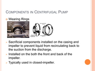
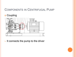
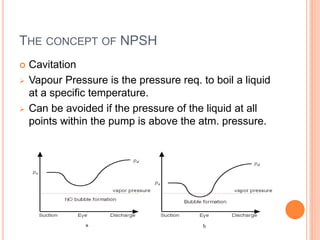
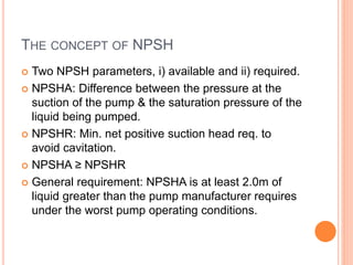
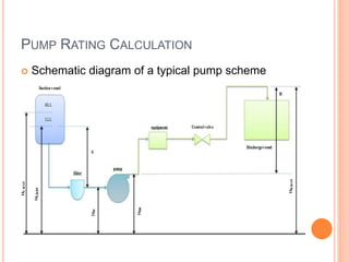
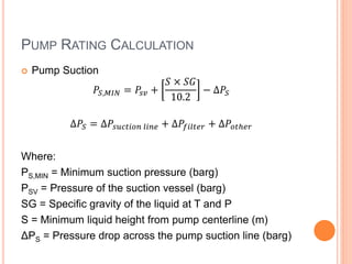
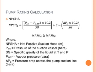
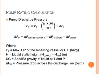

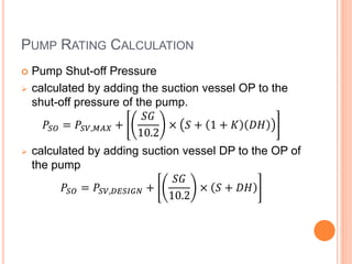
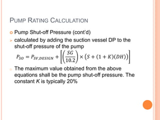

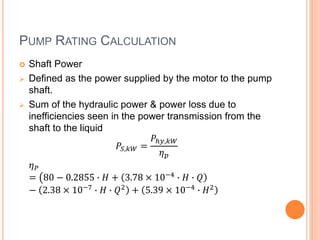
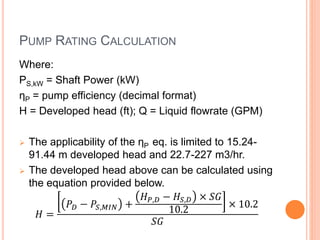
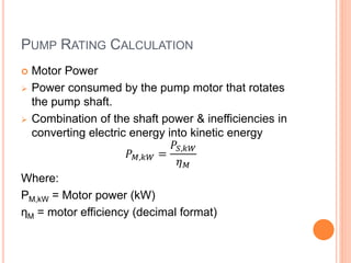
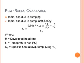
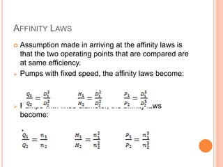

The document provides an overview of centrifugal pump operation, detailing principles like energy conversion and the components involved, including the impeller, casing, and stuffing box. It discusses important concepts such as net positive suction head (NPSH) and provides procedures for pump rating calculations, including suction pressure, discharge pressure, and power estimation. Additionally, it introduces affinity laws applicable under specific conditions, enhancing understanding of pump performance.


