Downloaded 6,736 times
![ Work is done by the impeller on the water
W=[Vw2U2-Vw1U1]/g
where,
W=work done per unit wg. of water per sec.
Vw2=whirl component of absolute vel. of jet at
outlet.
U2=tangential vel. of impeller at outlet.
Vw1=whirl component of absolute vel. of jet at
inlet.
U1=tangential vel. of impeller at inlet.](https://image.slidesharecdn.com/centrifugalpump-150225082938-conversion-gate01/85/Centrifugal-pump-16-320.jpg)
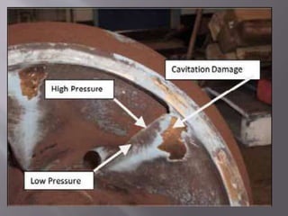


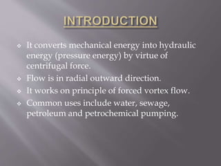
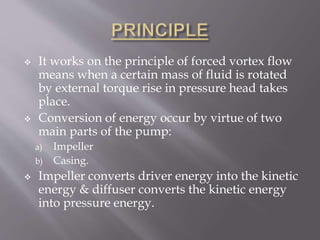
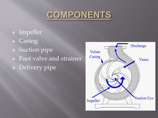
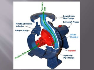
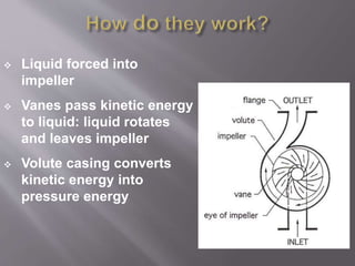
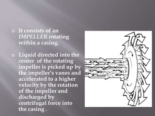
The document discusses centrifugal pumps. It describes how centrifugal pumps work by converting mechanical energy to hydraulic energy using centrifugal force. They work on the principle of forced vortex flow. Key components include an impeller that rotates and accelerates the fluid outward, and a casing that captures the fluid and converts its kinetic energy to pressure. Centrifugal pumps are used to pump liquids like water, sewage, petroleum and more. Performance curves are used to predict pump behavior under different operating conditions.


