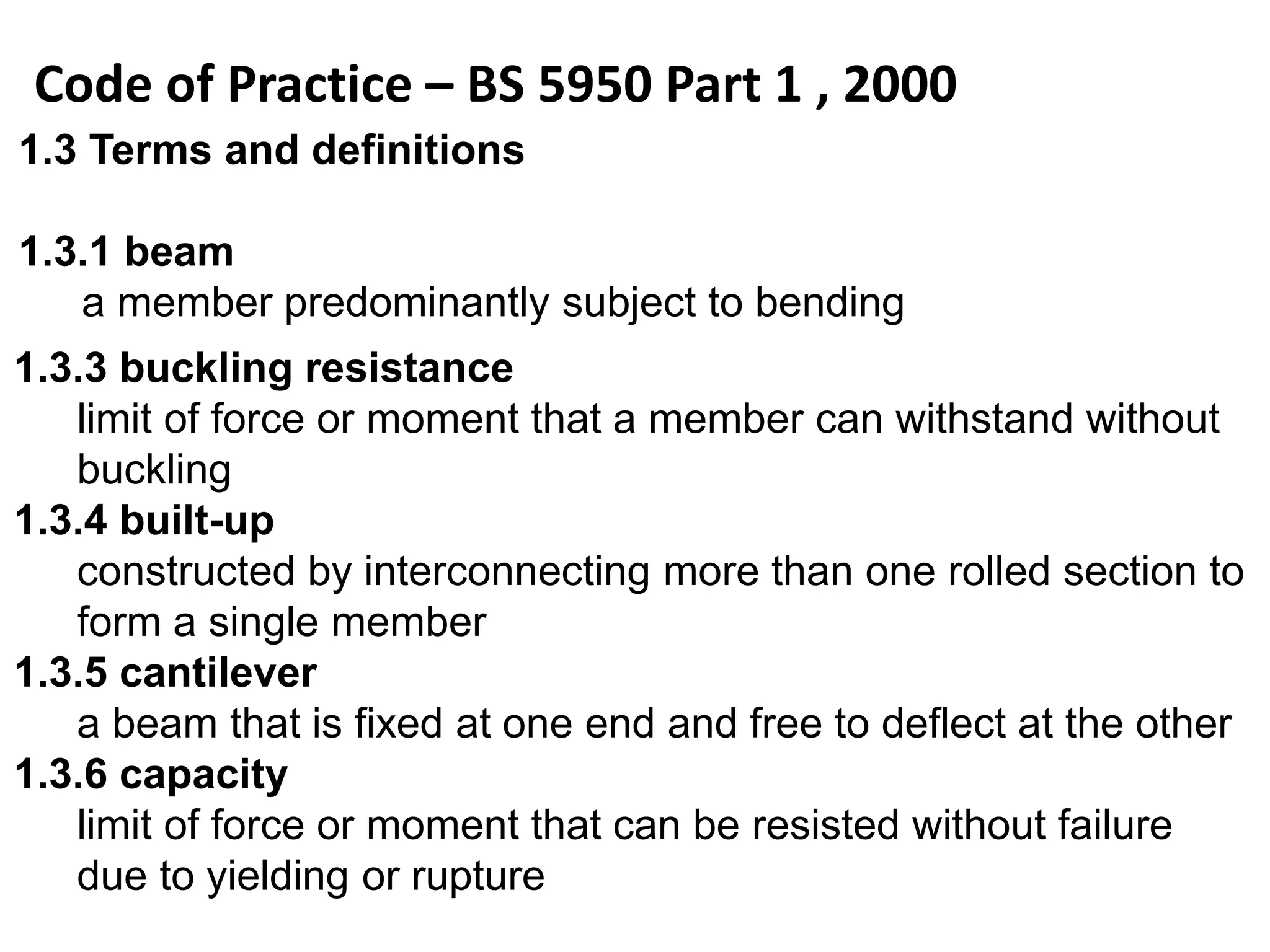
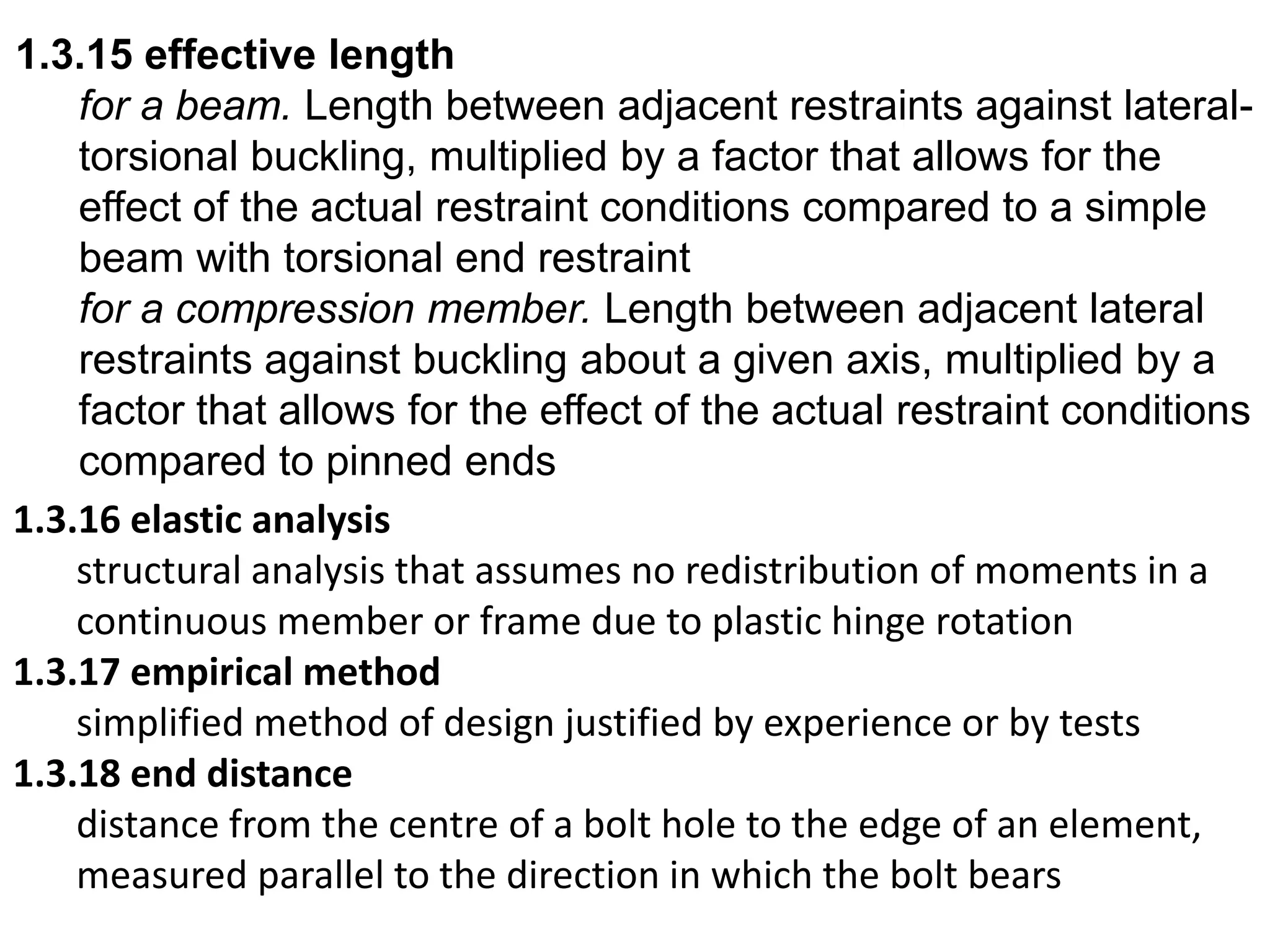
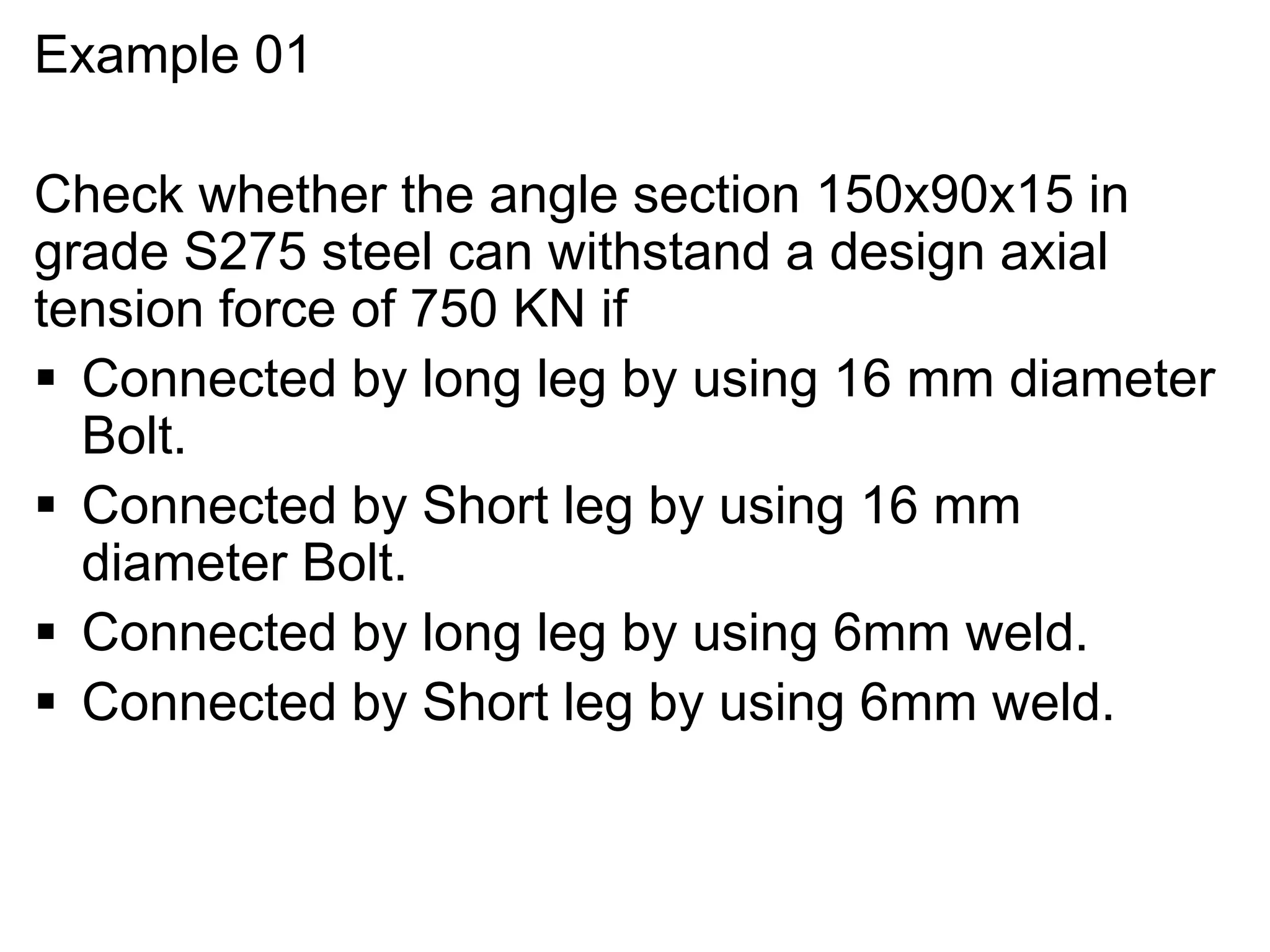
Design of steel structure as per is 800(2007)ahsanrabbani
It does not offer resistance against rotation and also termed as a hinged or pinned connections.
It transfers only axial or shear forces and it is not designed for moment
It is generally connected by single bolt/rivet and therefore full rotation is allowed
Composite construction or Composite Structure/FrameAbdul Rahman
Composite structure of steel and concrete has been explained under this ppt with examples, type of structural members, advantages and comparison with other structures like R.C.C structure and Steel structures.
This presentation is on design of welded and riveted connections in steel structures. in this presentation we learn briefly about these connections and design terminology about these connections.
Here we discussed about the balanced section,Under reinforced and Over reinforced sections and what are the failure and their moment of resistance.. and also comparison between among three sections
information on types of beams, different methods to calculate beam stress, design for shear, analysis for SRB flexure, design for flexure, Design procedure for doubly reinforced beam,
International Journal of Computational Engineering Research(IJCER) ijceronline
nternational Journal of Computational Engineering Research (IJCER) is dedicated to protecting personal information and will make every reasonable effort to handle collected information appropriately. All information collected, as well as related requests, will be handled as carefully and efficiently as possible in accordance with IJCER standards for integrity and objectivity.
Design of Beam- RCC Singly Reinforced BeamSHAZEBALIKHAN1
Concrete beams are an essential part of civil structures. Learn the design basis, calculations for sizing, tension reinforcement, and shear reinforcement for a concrete beam.
Experimental study on strength and flexural behaviour of reinforced concrete ...IOSR Journals
Abstract: Strength and flexural behaviour of reinforced concrete beams using deflected structural steel
reinforcement and the conventional steel reinforcement are conducted in this study. The reinforcement quantity
of both categories was approximately equalised. Mild steel flats with minimum thickness and corresponding
width are deflected to possible extent in a parabolic shape and semi-circular shape are fabricated and used as
deflected structural steel reinforcement in one part, whereas the fabrication of ribbed tar steel circular bars as
conventional reinforcement on the another part of the experiment for comparison in the concrete beams. All the
beams had same dimensions and same proportions of designed mix concrete, were tested under two point
loading system. As the result of experiments, it is found that the inverted catenary flats and their ties, transfers
the load through arch action of steel from loading points towards the supports before reaching the bottom
fibre at the centre of the beam as intended earlier. Thereby the load carrying capacity and the ductility ratio
has being increased in deflected structural steel reinforced beams when compared with ribbed tar steel
reinforced concrete beams, it is also observed that the failure mode (collapse pattern)is safer.
Keywords --Arch profile, Conventional steel reinforcement, Cracks, Collapse, Deflected structural steel,
Ductility ratio.
Quality defects in TMT Bars, Possible causes and Potential Solutions.PrashantGoswami42
Maintaining high-quality standards in the production of TMT bars is crucial for ensuring structural integrity in construction. Addressing common defects through careful monitoring, standardized processes, and advanced technology can significantly improve the quality of TMT bars. Continuous training and adherence to quality control measures will also play a pivotal role in minimizing these defects.
Overview of the fundamental roles in Hydropower generation and the components involved in wider Electrical Engineering.
This paper presents the design and construction of hydroelectric dams from the hydrologist’s survey of the valley before construction, all aspects and involved disciplines, fluid dynamics, structural engineering, generation and mains frequency regulation to the very transmission of power through the network in the United Kingdom.
Author: Robbie Edward Sayers
Collaborators and co editors: Charlie Sims and Connor Healey.
(C) 2024 Robbie E. Sayers
Cosmetic shop management system project report.pdfKamal Acharya
Buying new cosmetic products is difficult. It can even be scary for those who have sensitive skin and are prone to skin trouble. The information needed to alleviate this problem is on the back of each product, but it's thought to interpret those ingredient lists unless you have a background in chemistry.
Instead of buying and hoping for the best, we can use data science to help us predict which products may be good fits for us. It includes various function programs to do the above mentioned tasks.
Data file handling has been effectively used in the program.
The automated cosmetic shop management system should deal with the automation of general workflow and administration process of the shop. The main processes of the system focus on customer's request where the system is able to search the most appropriate products and deliver it to the customers. It should help the employees to quickly identify the list of cosmetic product that have reached the minimum quantity and also keep a track of expired date for each cosmetic product. It should help the employees to find the rack number in which the product is placed.It is also Faster and more efficient way.
Welcome to WIPAC Monthly the magazine brought to you by the LinkedIn Group Water Industry Process Automation & Control.
In this month's edition, along with this month's industry news to celebrate the 13 years since the group was created we have articles including
A case study of the used of Advanced Process Control at the Wastewater Treatment works at Lleida in Spain
A look back on an article on smart wastewater networks in order to see how the industry has measured up in the interim around the adoption of Digital Transformation in the Water Industry.
Courier management system project report.pdfKamal Acharya
It is now-a-days very important for the people to send or receive articles like imported furniture, electronic items, gifts, business goods and the like. People depend vastly on different transport systems which mostly use the manual way of receiving and delivering the articles. There is no way to track the articles till they are received and there is no way to let the customer know what happened in transit, once he booked some articles. In such a situation, we need a system which completely computerizes the cargo activities including time to time tracking of the articles sent. This need is fulfilled by Courier Management System software which is online software for the cargo management people that enables them to receive the goods from a source and send them to a required destination and track their status from time to time.
Sachpazis:Terzaghi Bearing Capacity Estimation in simple terms with Calculati...Dr.Costas Sachpazis
Terzaghi's soil bearing capacity theory, developed by Karl Terzaghi, is a fundamental principle in geotechnical engineering used to determine the bearing capacity of shallow foundations. This theory provides a method to calculate the ultimate bearing capacity of soil, which is the maximum load per unit area that the soil can support without undergoing shear failure. The Calculation HTML Code included.
Democratizing Fuzzing at Scale by Abhishek Aryaabh.arya
Presented at NUS: Fuzzing and Software Security Summer School 2024
This keynote talks about the democratization of fuzzing at scale, highlighting the collaboration between open source communities, academia, and industry to advance the field of fuzzing. It delves into the history of fuzzing, the development of scalable fuzzing platforms, and the empowerment of community-driven research. The talk will further discuss recent advancements leveraging AI/ML and offer insights into the future evolution of the fuzzing landscape.
CFD Simulation of By-pass Flow in a HRSG module by R&R Consult.pptxR&R Consult
CFD analysis is incredibly effective at solving mysteries and improving the performance of complex systems!
Here's a great example: At a large natural gas-fired power plant, where they use waste heat to generate steam and energy, they were puzzled that their boiler wasn't producing as much steam as expected.
R&R and Tetra Engineering Group Inc. were asked to solve the issue with reduced steam production.
An inspection had shown that a significant amount of hot flue gas was bypassing the boiler tubes, where the heat was supposed to be transferred.
R&R Consult conducted a CFD analysis, which revealed that 6.3% of the flue gas was bypassing the boiler tubes without transferring heat. The analysis also showed that the flue gas was instead being directed along the sides of the boiler and between the modules that were supposed to capture the heat. This was the cause of the reduced performance.
Based on our results, Tetra Engineering installed covering plates to reduce the bypass flow. This improved the boiler's performance and increased electricity production.
It is always satisfying when we can help solve complex challenges like this. Do your systems also need a check-up or optimization? Give us a call!
Work done in cooperation with James Malloy and David Moelling from Tetra Engineering.
More examples of our work https://www.r-r-consult.dk/en/cases-en/
TECHNICAL TRAINING MANUAL GENERAL FAMILIARIZATION COURSEDuvanRamosGarzon1
AIRCRAFT GENERAL
The Single Aisle is the most advanced family aircraft in service today, with fly-by-wire flight controls.
The A318, A319, A320 and A321 are twin-engine subsonic medium range aircraft.
The family offers a choice of engines
2. Design of Steel Structures
Carry out the design of
- Restrained & un restrained Steel Beams
- Axially loaded universal columns & those subject to
eccentric loading
- Slabs & Built up base's for axially loaded steel
columns
- Connections
3. Code of Practice – BS 5950 Part 1 , 2000
1.3 Terms and definitions
1.3.1 beam
a member predominantly subject to bending
1.3.3 buckling resistance
limit of force or moment that a member can withstand without
buckling
1.3.4 built-up
constructed by interconnecting more than one rolled section to
form a single member
1.3.5 cantilever
a beam that is fixed at one end and free to deflect at the other
1.3.6 capacity
limit of force or moment that can be resisted without failure
due to yielding or rupture
4. 1.3.7 column
a vertical member carrying axial force and possibly moments
1.3.10 connection
location where a member is fixed to a supporting member or
other support, including the bolts, welds and other material
used to transfer loads
5. 1.3.11 dead load
a load of constant magnitude and position that acts
permanently, including self-weight
1.3.12 design strength
the notional yield strength of the material used in design,
obtained by applying partial factors to the specified minimum
yield strength and tensile strength of the material
1.3.13 dynamic load
part of an imposed load resulting from motion
1.3.14 edge distance
distance from the centre of a bolt hole to the nearest edge of
an element, measured perpendicular to the direction in which
the bolt bears
6. 1.3.15 effective length
for a beam. Length between adjacent restraints against lateral-
torsional buckling, multiplied by a factor that allows for the
effect of the actual restraint conditions compared to a simple
beam with torsional end restraint
for a compression member. Length between adjacent lateral
restraints against buckling about a given axis, multiplied by a
factor that allows for the effect of the actual restraint conditions
compared to pinned ends
1.3.16 elastic analysis
structural analysis that assumes no redistribution of moments in a
continuous member or frame due to plastic hinge rotation
1.3.17 empirical method
simplified method of design justified by experience or by tests
1.3.18 end distance
distance from the centre of a bolt hole to the edge of an element,
measured parallel to the direction in which the bolt bears
7. 1.3.19 factored load
specified load multiplied by the relevant partial factor
1.3.20 fatigue
damage to a structural member caused by repeated
application of stresses that are insufficient to cause failure by a
single application
1.3.21 foundation
part of a structure that distributes load directly to the ground
1.3.22 friction grip connection
a bolted connection that relies on friction to transmit shear
between components
1.3.23 H-section
section with a central web and two flanges, that has an overall
depth not greater than 1.2 times its overall width
1.3.24 hybrid section
I-section with a web of a lower strength grade than the flanges
1.3.25 I-section
section with a central web and two flanges, that has an overall
depth greater than 1.2 times its overall width
8. 1.3.26 imposed load
load on a structure or member, other than wind load,
produced by the external environment or the intended
occupancy or use
1.3.27 instability
inability to carry further load due to vanishing stiffness
1.3.28 joint
element of a structure that connects members together and
enables forces and moments to be transmitted between them
1.3.29 lateral restraint
for a beam. Restraint that prevents lateral movement of the
compression flange
for a compression member. Restraint that prevents lateral
movement of the member in a given plane
9. Design Process
1. Define the problem while appreciating the client’s
requirements and constraints
2. Consideration of possible structural arrangements
3. Selection of most satisfactory arrangements
4. Detailed structural Design
5. Preparation of Drawings and specifications
6. Construction Phase
10. Structural Forms
Structures are essentially a combination of members
which can be classified according to their main
functions
Tension Members
Compression Members
Flexural members
Torsion members
Trusses
Frames
Surface Members
11.
12. Tension members
These are subject to a Pulling Action. An
important characteristic of a member stressed in
tension is that it need no bending stiffness. Thus
ropes & cables can be used for members stressed in
tension.
Compression members
These are subject to a pushing action.
Compression members must have bending stiffness.
On the application of a slight transverse displacement,
the applied force will increase deformation
13. Flexural Members (Beams)
A Beam supports the load by utilizing its resistance
to bending and shear. Bending causes a tension and
compression forces in a beam.
Shear or the resistance to sliding or slipping is also
induced in a beam.
A Slab is a wide beam. It can be bend in tow
directions depending on the method of support.
Torsion Members
Torsion occurs in a member when the load tends
to twist it. Torsion induces shear stresses in a member.
Shear Members
A plane type structural members subjected
to an applied force in its own plane.
14. Trusses
trusses are triangulated framework consisting of
tension and compression members.
The members are considered to be hinged or
pinned to each other. The members are free to rotate at
the ends.
Rotation at the joints is necessary to
accommodate the small changes in length that occur
due to the tensile and compressive forces in the
members.
Trusses may be two dimensional or three
dimensional.
15. Frames
Triangulation can be avoided by using rigid joints
instead of pinned joints.
Structural systems in which the members are
connected to each other with rigid joints are called
Frames.
Surface Members.
plates are planar, surface forming structural
elements capable of carrying bending forces such as in
slabs or in plane forces (axial and or shear) as in walls.
Shells are curved surface forming structural
elements capable of carrying forces through in plane
action.
Shells may be singly curved or doubly curved.
16. Design of Structural Elements in Steel
Advantage of Steel.
Steel structures are fast and easy to erect.
No formwork no false work is required.
Much of the structures can be fabricated away from the
site. Since the structure is self supporting no delays are
experienced due to slow strength gain.
Good dimensional Control.
Prefabrication in the factory ensures accurate work.
Low self weight
Large clear spans are possible. Minimum Carnage.
Adaptability
Later modification is relatively easy and inexpensive
with minimum disruption.
17. Properties of the steel
Structural steel is composed of about 98% iron
with small percentages of Carbon, Silicon, Manganese,
Phosphorus, Sulper, Niobium & Vanadium.
The Carbon content is restricted to about 0.25%
Although an increased Carbon content increases
strength & Hardness, it reduces Ductility & Toughness.
Hence the Carbon content is limited to produced
to steel that is weldable and not brittle.
Niobium & Vanadium are introduced to raise the
yield strength of the steel.
Manganese is introduce to improve the corrosion
resistance. Phosphorus and Sulpher are impurities.
19. The Yield stress depends on the chemical
composition of the steel.
It also varies with the heat treatment used and
the amount of working load that occurs during the
rolling process.
Hence thinner plates have a higher yield stress
than thicker plates of the same composition.
Table 9 of the BS 5950 part 1 given the design
strength of the steel.
22. Design of tension Members
Design Considerations
It must have adequate cross sectional area and
tensile strength to withstand the applied tensile
force.
The end connection often cause a loss of
efficiency due to loss of area at Bolt holes and
eccentricity of the connection.
23. Tensile capacity of an axially loaded Member.
4.6.1 Tension capacity
The tension capacity Pt of a member should
generally be obtained from:
Pt = pyAe
Ae is the sum of the effective net areas ae of all the
elements of the cross-section, determined from 3.4.3,
but not more than 1.2 times the total net area An.
Py Design strenth from Table 9
24. 3.4.3 Effective net area
The effective net area Ae of each element of a cross-
section with bolt holes should be determined from:
Ae = KeΣan but ae≤ ag
in which the effective net area coefficient Ke is given by:
— for grade S 275: Ke = 1.2
— for grade S 355: Ke = 1.1
— for grade S 460: Ke = 1.0
— for other steel grades: Ke = (Us/1.2)/py
where
ag is the gross area of the element;
an is the net area of the element;
py is the design strength;
Us is the specified minimum tensile strength
25. 4.6.2 Members with eccentric connections
If members are connected eccentric to their axes, the
resulting moments should generally be allowed for in accordance
with 4.8.2. However, angles, channels or T-sections with eccentric
end connections may be treated as axially loaded by using the
reduced tension capacity given in 4.6.3.
4.6.3.1 Single angle, channel or T-section
members
For a simple tie, designed as axially loaded, consisting of a
single angle connected through one leg only, a single channel
connected only through the web or a T-section connected only
through the flange, the tension capacity should be obtained as
follows:
— for bolted connections: Pt = py(Ae – 0.5a2)
— for welded connections: Pt = py(Ag – 0.3a2)
26. in which:
a2 = Ag – a1
where
Ag is the gross cross-sectional area, see 3.4.1;
a1 is the gross area of the connected element,
taken as the product of its thickness and the overall
leg width for an angle, the overall depth for a channel
or the flange width for a T-section.
4.6.3.2 Double angle, channel or T-section
members
— for bolted connections: Pt = py(Ae – 0.25a2)
— for welded connections: Pt = py(Ag – 0.15a2)
27. Example 01
Check whether the angle section 150x90x15 in
grade S275 steel can withstand a design axial
tension force of 750 KN if
Connected by long leg by using 16 mm diameter
Bolt.
Connected by Short leg by using 16 mm
diameter Bolt.
Connected by long leg by using 6mm weld.
Connected by Short leg by using 6mm weld.
28. • Example 2
Determined the tensile capacity of a connection shown
in figure (a) and (b). The steel grade S275 and the Bolt
are 20 mm diameter.
29. Design Considerations
• A compression members subjects to direct
pushing action, Fails due to buckling.
– It may be either by overall flexural buckling or
by local buckling of thin plate elements of the
section.
• Bending is often induced in a compression
member due to eccentric connections and
lateral loading on the member.
Design of Compression Members
30. • Overall Flexural buckling is governed by the
slenderness ratio
– Which depends on
• Length of the Member
• Type of end resistance
• Cross sectional shape
• Type of the Member
• Local Buckling
– Depends on the slenderness of the components
plate elements of the section
– Sections are classified into Plastic, Compact,
Semi Compact, or Slender depending on the
width to thickness ratios.(Table 11, 12)
31.
32.
33. Determination of Compression capacity
• For Plastic, Compact or Semi Compact Sections
Pc = Ag.Pc
• For Slender Sections
Pc = Aeff.Pcs
Where
Aeff :- Effective cross Sectional Area ( cl 3.6)
Ag :- Gross cross sectional Area(cl 3.4.1)
Pc :- Compressive strength (cl 4.7.5)
Pcs :- value of Pc for a reduced slenderness of
λ(Aeff/Ag)0.5 In which λ is based on the radius of
gyration r of the gross cross section.
34. • The compressive strength Pc of a section is
obtained from strut tables 24 (a) to (d).
• Table 23 indicates for any shape, thickness of
steel and the axis of buckling, which of the
four struts Tables 24(a) to 24(d)
Pc depends on:-
– Slenderness λ (cl 4.7.2)
– Design strength Py (table 9 & cl 3.6)
λ = Effective length (Le) / Radius of Gyration ( r )
Le given in Table 22.
35.
36.
37.
38. Design of flexural members
Design considerations
A flexural or bending member commonly referred as a beam
is subject to a compression of tensile, compressive and
shear stresses.Thus a beam could fail in a number of
different modes.
• The beam could fail when the maximum tensile and
compressive stresses have reached the yield stresses of steel.
• The beam also fails when the maximum shear stress is
exceeded.
• The compressive forces in the section could also fail by lateral
torsional buckling and or local buckling cause premature
failure
• Concentrated forces acting through the web can also cause
thin web sections to buckle or crush.
• Excessive deflection may also be considered a design failure.
39. Determination of shear capacity of a flexural
Member (cl 4.2.3)
The Shear capacity Pv given by:
Where;-
Py - is the design strength from Table 9
Av - is the shear area of section as defined in cl 4.2.3
43. Design of connections
Design considerations
However much care and attention is given to the
determination of structural layout and member sizes,
the resulting structure will not behave as the designer
intends unless due consideration is given to the
connections between such members.
The connections must be
– Capable of transmitting the forces and moments that the
members have to resist.
– Easy to install, inspect and maintain
– Economical
44. Design of connections
Design considerations
However much care and attention is given to the
determination of structural layout and member sizes,
the resulting structure will not behave as the designer
intends unless due consideration is given to the
connections between such members.
The connections must be
– Capable of transmitting the forces and moments that the
members have to resist.
– Easy to install, inspect and maintain
– Economical
45. Bolt Connections
Bolts subject to shear forces can fail in deferent ways.
– Shear on Bolt Shank
– Bearing on plate and Bolt
– Tension Failure of plates
– Insufficient end distance.
46.
47. Determination of shear capacity of a bolt. (cl 6.3.2)
Shear capacity of a bolt, Ps is given by
48. Diameter of Bolt (mm) Tensile area of Bolt (mm2)
12 84.5
16 157
20 245
22 303
24 353
49. Large joints (cl 6.3.2.3)
When Tg ≥ 5d,
Where,
Tg is the total thickness of connection.
d is the Bolt diameter.
Large joints (cl 6.3.2.5)
When Lj ≥ 500 mm,
Where,
Lj is the Joint length in mm
53. Determination of Tensile capacity of a bolt.
(cl 6.3.4)
The tensile force for bolt Ft transmitted by the connection
should not exceed the nominal tension capacity Pnom of the
Bolt.
54. Faster Spacing, end and edge distances.(cl 6.2)
Minimum Spacing - 2.5 d (d = Nominal diameter of the bolt)
Maximum Spacing - 14 t ( t = thickness of thinner element)
Minimum end and edge
distance
- 1.25x Ø hole (rolled, machine flame cut)
- 1.4 x Ø hole (sheared, hand flame cut)
Maximum edge distance - 11 x t x ε (ε = (275/Py)0.5 , t = thickness)
55. Example :03
Check whether the M16 Bolts (G 4.6) shown in figure are
capable of carrying the axial force of 100 KN in the bracing
member. Assume slandered clearance at Bolt hole.
Example :04
Determined the maximum axial force that can be resisted
by the plate joint shown in the figure. Assume slandered
clearance at hole and steel grade S275.
56. Welding Connections (Cl 6.7)
Design strength Pw (Cl 6.8.5)
Design strength pw of a fillet weld is obtained from table 37
6.8.2 Effective length
The effective length of a fillet weld should be taken as the length
over which the fillet is full size. In the absence of better
information this may be taken as equal to the overall length, less
one leg length s for each end that does not continue around a
corner. A fillet weld with an effective length less than 4s or less
than 40 mm should not be used to carry load.
57.
58. 6.8.3 Throat size
The effective throat size a of a fillet weld should be taken as
the perpendicular distance from the root of the weld to a
straight line joining the fusion faces that lies just within the
cross-section of the weld, see Figure 29.
59. Example :05
Check whether the welded connection shown in figure A
& B can withstand an Design axial force of 166KN. Assume
6mm fillet welled using 35EC