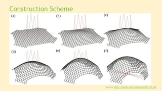
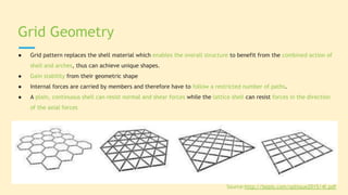
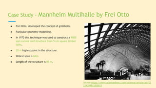
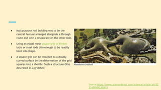
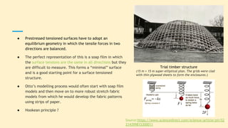
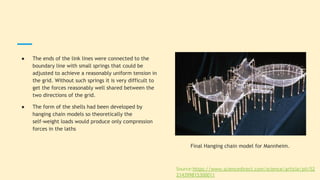
GRID SHELL
Sahil Ahmed - 01
Ishwar Bhat - 04
Utsav Chaudhury - 09
Dolly Gada - 17
Jahnavi Joshi - 22
Introduction:
A shell is a natural, extremely strong three dimensional structure, that resists applied loads through its inherent
shape. There are a several forms of structure that belong to this group of load bearing structures, which carry
applied loads mainly by way of membrane forces.
Key features of a Grid Shell structure:
● Tri-dimensional surfaces
● Self supported structures, no additional frames or columns required
● Resist load with geometry
Construction Scheme
Source:http://bepls.com/splissue2015/4f.pdf
Classification of Gridshell:
● A gridshell may be made of different geometric modules. But the most used modules as the basic patterns are
included, square, diamond, triangular and hexagonal grid. Triangular format geometry is of the inherent stability.
Gridshells facilitate development in three directions:
1) Reuse of historic buildings with appropriate functions,
2) Materials can save up to 50% compared with conventional frame structures and ability to be build structures
with different materials
3) Greater amounts of natural light enter the building
● Any curved surface with very low depth to span ratio may be regarded as a gridshell.
Gridshells may be classified in terms of :
1. Geometry of the grid
2. Type of Load transfer
3. Form
● Grid pattern replaces the shell material which enables the overall structure to benefit from the combined action of
shell and arches, thus can achieve unique shapes.
● Gain stability from their geometric shape
● Internal forces are carried by members and therefore have to follow a restricted number of paths.
● A plain, continuous shell can resist normal and shear forces while the lattice shell can resist forces in the direction
of the axial forces
Grid Geometry
Source:http://bepls.com/splissue2015/4f.pdf
● Feature of grid structures is their ability in two or more way load transfer.
● The system transfers loads from multiple directions and hence can be classified as two - way, three - way
and four - way grids.
Types of Load Transfer
Source:http://bepls.com/splissue2015/4f.pdf
Grid shells can be divided into different categories according to structure:
1. Curved in one direction : Cylindrical Shells:
2. Two- directional shells : All kinds of domes
3. Shells with curvatures in opposite direction
4. Shells with free - form curved surface
Form
Source:http://bepls.com/splissue2015/4f.pdf
1. The common structures for gridshell are made of timber, which can be bent elastically without breaking. Timber is
used due to low-density and high strain range.
2. Timber gridshells are of spatial structures and combine structural efficiency with a pleasant appearance.
3. They are used in temporary buildings such as temporary exhibitions, or when rapid construction is concerned, can
be customized.
4. Fiber glass reinforced polymer materials also can be used in the system. Fiber glass reinforced polymer materials
have greater stiffness than timber and thus, for a given geometry of the gridshell.
5. However, fiberglass reinforced and composite materials can be considered as an alternative to timber members.
Material
Source:http://bepls.com/splissue2015/4f.pdf
1. Joints in the structure should not only join the members to each other, but should provide rotations while
maintaining the geometry of the grid.
2. The ability of the nodes rotations is the unique characteristics of the structure and provides the possibility of
building free and complex forms.
3. It is well known that the nodes are of critical points of the structure and their design requires a high level of
creativity and innovation.
4. However, two types of nodes that are typically used in these structures are slot node and plate node.
Joints
Source:http://bepls.com/splissue2015/4f.pdf
Advantages & Disadvantages of Grid Shells
● The benefits of using a grid shell compared to either the conventional slab and frame system or the continuous
shell are both aesthetic and structural.
● The curved shapes often used for concrete shells are naturally strong structures.
● Shell allowing wide areas to be spanned without the use of internal supports, giving an open, unobstructed
interior.
● As concrete is relatively inexpensive and easily cast into compound curves
However, there are a few stability failure on gridshell structures including:
● Members buckling means a member buckling without influence on the rest of the structure
● Local instability, meaning the failure of one or more nodes
● Global instability, meaning the structure buckles as a whole.
Source:https://www.slideshare.net/SusmitaPaul12/shell-structure
Case Study - Mannheim Multihalle by Frei Otto
● Frei Otto, developed the concept of gridshells.
● Funicular geometry modelling.
● In 1970 this technique was used to construct a 9000
sqm curved roof structure from 5 cm square timber
laths.
● 20 m highest point in the structure.
● Widest span is 60m.
● Length of the structure is 85 m.
Source:https://www.sciencedirect.com/science/article/pii/S2
214399815300011
● Multipurpose hall building was to be the
central feature arranged alongside a through
route and with a restaurant on the other side.
● Using an equal mesh square grid of timber
laths or steel rods thin enough to be readily
bent into shape.
● A square grid can be moulded to a doubly
curved surface by the deformation of the grid
squares into a rhombi. Such a structure Otto
described as a gridshell
Source:https://www.sciencedirect.com/science/article/pii/S2
214399815300011
● Prestressed tensioned surfaces have to adopt an
equilibrium geometry in which the tensile forces in two
directions are balanced.
● The perfect representation of this is a soap film in which
the surface tensions are the same in all directions but they
are difficult to measure. This forms a “minimal” surface
and is a good starting point for a surface tensioned
structure.
● Otto’s modelling process would often start with soap film
models and then move on to more robust stretch fabric
models from which he would develop the fabric patterns
using strips of paper.
● Hookean principle ?
Trial timber structure
(15 m × 15 m super-elliptical plan. The grids were clad
with thin plywood sheets to form the enclosures.)
Source:https://www.sciencedirect.com/science/article/pii/S2
214399815300011
● The ends of the link lines were connected to the
boundary line with small springs that could be
adjusted to achieve a reasonably uniform tension in
the grid. Without such springs it is very difficult to
get the forces reasonably well shared between the
two directions of the grid.
● The form of the shells had been developed by
hanging chain models so theoretically the
self-weight loads would produce only compression
forces in the laths
Final Hanging chain model for Mannheim.
Source:https://www.sciencedirect.com/science/article/pii/S2
214399815300011
Timber lath cross junction
joineries
Ground connection detail
TImber lath cross joinery with
steel rod braces
Case Study - Temporary cathedral by ATELIER
D'INGÉNIERIE
● Designed as a temporary cathedral.
● Made of composite materials: Glass fiber reinforced
polymer tubes (GFRP), covered by a PVC coated
fabric.
● It weighs 5 kg/sqm and Area of 350sqm.
● Height - 7m.
● Span - 17m.
● Length - 29m.
Source : https://www.tess.fr/en
● A circular seating arrangement is often
considered the most convivial
● The final form is based loosely on two
adjacent semi spherical volumes of different
size, which are merged into one complex
form.
● It was therefore decided that the two
spherical virtual forms, which would be joined
to make the final form, would be arranged
not in a asymmetrical axial manner.
Source : https://www.tess.fr/en
Form of the building
Construction details
● A regular planar grid made of long
continuous linear members is built on the
ground (Fig. 1).
● The elements are pinned together so the
grid has no in plane shear stiffness and can
accommodate large-scale deformations
during erection (Fig. 2).
● Then, the grid is bent elastically to its final
shape (Fig. 3).
● Finally, the grid is frozen in the desired
shape with a third layer of bracing members
(Fig. 4) and the structure becomes a shell.
Source : https://www.tess.fr/en
Construction details
One can identify 4 major structural details:
● a) The swivel coupler for connecting
composite pipes to assemble the grid
● b) The steel sleeve for connecting several
composite pipes to make long members
from initially short piece of tubes
● c) Ground anchorages for fixing the
structure to the concrete slab
● d) The lacing edge beam of the fabric
Source : https://www.tess.fr/en
Case Study: Centre Pompidou-Metz
Architects: Shigeru Ban Architects; Area: 11330 m²; Year: 2010
Building Function:
1.The main purpose for this annex to the Centre Pompidou was to be
able to show more works to the public
2.To be able to display the very large works that cannot be shown in
the Paris museum due to the 5.5m ceiling height under the beams.
3. The main purpose for this annex to the Centre Pom To
accommodate this requirement, 18m was maintained as the highest
ceiling height under the Grand Nef Gallery.
Roof:
1.The undulating laminated timber roof structure surrounds a
77-metre metal spire. The roof, inspired by a woven chinese hat.
2.The structure is made from highly resistant glue-laminated wood,
providing a mesh that can span lengths of about 40 metres.
3. Total there are 1800 individual beams with no one being the
same. when all beams are laid out flatly in a line they measure to be
15 km in length. Highest point the roof reaches up to 77 meters.
This waterproof material creates a naturally temperate
environment, helping satisfy the building’s demanding energy
requirements and ensuring that works of art are exposed and
conserved in the best possible conditions.
Source:https://www.archdaily.com/490141/centre-pompidou-metz-
shigeru-ban-architects?ad_source=search&ad_medium=search_result
_all
Thank you

Building Construciton techniques - Grid shells

  • 1.
    GRID SHELL Sahil Ahmed- 01 Ishwar Bhat - 04 Utsav Chaudhury - 09 Dolly Gada - 17 Jahnavi Joshi - 22
  • 2.
    Introduction: A shell isa natural, extremely strong three dimensional structure, that resists applied loads through its inherent shape. There are a several forms of structure that belong to this group of load bearing structures, which carry applied loads mainly by way of membrane forces. Key features of a Grid Shell structure: ● Tri-dimensional surfaces ● Self supported structures, no additional frames or columns required ● Resist load with geometry
  • 3.
  • 4.
    Classification of Gridshell: ●A gridshell may be made of different geometric modules. But the most used modules as the basic patterns are included, square, diamond, triangular and hexagonal grid. Triangular format geometry is of the inherent stability. Gridshells facilitate development in three directions: 1) Reuse of historic buildings with appropriate functions, 2) Materials can save up to 50% compared with conventional frame structures and ability to be build structures with different materials 3) Greater amounts of natural light enter the building ● Any curved surface with very low depth to span ratio may be regarded as a gridshell. Gridshells may be classified in terms of : 1. Geometry of the grid 2. Type of Load transfer 3. Form
  • 5.
    ● Grid patternreplaces the shell material which enables the overall structure to benefit from the combined action of shell and arches, thus can achieve unique shapes. ● Gain stability from their geometric shape ● Internal forces are carried by members and therefore have to follow a restricted number of paths. ● A plain, continuous shell can resist normal and shear forces while the lattice shell can resist forces in the direction of the axial forces Grid Geometry Source:http://bepls.com/splissue2015/4f.pdf
  • 6.
    ● Feature ofgrid structures is their ability in two or more way load transfer. ● The system transfers loads from multiple directions and hence can be classified as two - way, three - way and four - way grids. Types of Load Transfer Source:http://bepls.com/splissue2015/4f.pdf
  • 7.
    Grid shells canbe divided into different categories according to structure: 1. Curved in one direction : Cylindrical Shells: 2. Two- directional shells : All kinds of domes 3. Shells with curvatures in opposite direction 4. Shells with free - form curved surface Form Source:http://bepls.com/splissue2015/4f.pdf
  • 8.
    1. The commonstructures for gridshell are made of timber, which can be bent elastically without breaking. Timber is used due to low-density and high strain range. 2. Timber gridshells are of spatial structures and combine structural efficiency with a pleasant appearance. 3. They are used in temporary buildings such as temporary exhibitions, or when rapid construction is concerned, can be customized. 4. Fiber glass reinforced polymer materials also can be used in the system. Fiber glass reinforced polymer materials have greater stiffness than timber and thus, for a given geometry of the gridshell. 5. However, fiberglass reinforced and composite materials can be considered as an alternative to timber members. Material Source:http://bepls.com/splissue2015/4f.pdf
  • 9.
    1. Joints inthe structure should not only join the members to each other, but should provide rotations while maintaining the geometry of the grid. 2. The ability of the nodes rotations is the unique characteristics of the structure and provides the possibility of building free and complex forms. 3. It is well known that the nodes are of critical points of the structure and their design requires a high level of creativity and innovation. 4. However, two types of nodes that are typically used in these structures are slot node and plate node. Joints Source:http://bepls.com/splissue2015/4f.pdf
  • 10.
    Advantages & Disadvantagesof Grid Shells ● The benefits of using a grid shell compared to either the conventional slab and frame system or the continuous shell are both aesthetic and structural. ● The curved shapes often used for concrete shells are naturally strong structures. ● Shell allowing wide areas to be spanned without the use of internal supports, giving an open, unobstructed interior. ● As concrete is relatively inexpensive and easily cast into compound curves However, there are a few stability failure on gridshell structures including: ● Members buckling means a member buckling without influence on the rest of the structure ● Local instability, meaning the failure of one or more nodes ● Global instability, meaning the structure buckles as a whole. Source:https://www.slideshare.net/SusmitaPaul12/shell-structure
  • 11.
    Case Study -Mannheim Multihalle by Frei Otto ● Frei Otto, developed the concept of gridshells. ● Funicular geometry modelling. ● In 1970 this technique was used to construct a 9000 sqm curved roof structure from 5 cm square timber laths. ● 20 m highest point in the structure. ● Widest span is 60m. ● Length of the structure is 85 m. Source:https://www.sciencedirect.com/science/article/pii/S2 214399815300011
  • 12.
    ● Multipurpose hallbuilding was to be the central feature arranged alongside a through route and with a restaurant on the other side. ● Using an equal mesh square grid of timber laths or steel rods thin enough to be readily bent into shape. ● A square grid can be moulded to a doubly curved surface by the deformation of the grid squares into a rhombi. Such a structure Otto described as a gridshell Source:https://www.sciencedirect.com/science/article/pii/S2 214399815300011
  • 13.
    ● Prestressed tensionedsurfaces have to adopt an equilibrium geometry in which the tensile forces in two directions are balanced. ● The perfect representation of this is a soap film in which the surface tensions are the same in all directions but they are difficult to measure. This forms a “minimal” surface and is a good starting point for a surface tensioned structure. ● Otto’s modelling process would often start with soap film models and then move on to more robust stretch fabric models from which he would develop the fabric patterns using strips of paper. ● Hookean principle ? Trial timber structure (15 m × 15 m super-elliptical plan. The grids were clad with thin plywood sheets to form the enclosures.) Source:https://www.sciencedirect.com/science/article/pii/S2 214399815300011
  • 14.
    ● The endsof the link lines were connected to the boundary line with small springs that could be adjusted to achieve a reasonably uniform tension in the grid. Without such springs it is very difficult to get the forces reasonably well shared between the two directions of the grid. ● The form of the shells had been developed by hanging chain models so theoretically the self-weight loads would produce only compression forces in the laths Final Hanging chain model for Mannheim. Source:https://www.sciencedirect.com/science/article/pii/S2 214399815300011
  • 15.
    Timber lath crossjunction joineries Ground connection detail TImber lath cross joinery with steel rod braces
  • 16.
    Case Study -Temporary cathedral by ATELIER D'INGÉNIERIE ● Designed as a temporary cathedral. ● Made of composite materials: Glass fiber reinforced polymer tubes (GFRP), covered by a PVC coated fabric. ● It weighs 5 kg/sqm and Area of 350sqm. ● Height - 7m. ● Span - 17m. ● Length - 29m. Source : https://www.tess.fr/en
  • 17.
    ● A circularseating arrangement is often considered the most convivial ● The final form is based loosely on two adjacent semi spherical volumes of different size, which are merged into one complex form. ● It was therefore decided that the two spherical virtual forms, which would be joined to make the final form, would be arranged not in a asymmetrical axial manner. Source : https://www.tess.fr/en Form of the building
  • 18.
    Construction details ● Aregular planar grid made of long continuous linear members is built on the ground (Fig. 1). ● The elements are pinned together so the grid has no in plane shear stiffness and can accommodate large-scale deformations during erection (Fig. 2). ● Then, the grid is bent elastically to its final shape (Fig. 3). ● Finally, the grid is frozen in the desired shape with a third layer of bracing members (Fig. 4) and the structure becomes a shell. Source : https://www.tess.fr/en
  • 19.
    Construction details One canidentify 4 major structural details: ● a) The swivel coupler for connecting composite pipes to assemble the grid ● b) The steel sleeve for connecting several composite pipes to make long members from initially short piece of tubes ● c) Ground anchorages for fixing the structure to the concrete slab ● d) The lacing edge beam of the fabric Source : https://www.tess.fr/en
  • 20.
    Case Study: CentrePompidou-Metz Architects: Shigeru Ban Architects; Area: 11330 m²; Year: 2010 Building Function: 1.The main purpose for this annex to the Centre Pompidou was to be able to show more works to the public 2.To be able to display the very large works that cannot be shown in the Paris museum due to the 5.5m ceiling height under the beams. 3. The main purpose for this annex to the Centre Pom To accommodate this requirement, 18m was maintained as the highest ceiling height under the Grand Nef Gallery.
  • 21.
    Roof: 1.The undulating laminatedtimber roof structure surrounds a 77-metre metal spire. The roof, inspired by a woven chinese hat. 2.The structure is made from highly resistant glue-laminated wood, providing a mesh that can span lengths of about 40 metres. 3. Total there are 1800 individual beams with no one being the same. when all beams are laid out flatly in a line they measure to be 15 km in length. Highest point the roof reaches up to 77 meters. This waterproof material creates a naturally temperate environment, helping satisfy the building’s demanding energy requirements and ensuring that works of art are exposed and conserved in the best possible conditions.
  • 22.
  • 23.