Trusses
•
1 like•2,885 views

Civil Engineering is the Branch of Engineering.The Civil engineering field requires an understanding of core areas including Mechanics of Solids, Structural Mechanics - I, Building Construction Materials, Surveying - I, Geology and Geotechnical Engineering, Structural Mechanics, Building Construction, Water Resources and Irrigation, Environmental Engineering, Transportation Engineering, Construction and Project Management. Ekeeda offers Online Mechanical Engineering Courses for all the Subjects as per the Syllabus Visit us: https://ekeeda.com/streamdetails/stream/civil-engineering

Recommended
Recommended
More Related Content
What's hot
What's hot (20)
Similar to Trusses
Similar to Trusses (20)
More from Ekeeda
More from Ekeeda (20)
Recently uploaded
Recently uploaded (20)
Trusses
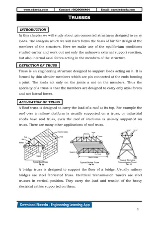
- 1. www.ekeeda.com Contact : 9029006464 Email : care@ekeeda.com 1 P INTRODUCTION In this chapter we will study about pin connected structures designed to carry loads. The analysis which we will learn forms the basis of further design of the members of the structure. Here we make use of the equilibrium conditions studied earlier and work out not only the unknown external support reaction, but also internal axial forces acting in the members of the structure. DEFINITION OF TRUSS Truss is an engineering structure designed to support loads acting on it. It is formed by thin slender members which are pin connected at the ends forming a joint. The loads act only on the joints a not on the members. Thus the specialty of a truss is that the members are designed to carry only axial forces and not lateral forces. APPLICATION OF TRUSS A Roof truss is designed to carry the load of a roof at its top. For example the roof over a railway platform is usually supported on a truss, or industrial sheds have roof truss, even the roof of stadiums is usually supported on truss. There are many other applications of roof truss. A bridge truss is designed to support the floor of a bridge. Usually railway bridges are steel fabricated truss. Electrical Transmission Towers are steel trusses in vertical position. They carry the load and tension of the heavy electrical cables supported on them. Trusses
- 2. www.ekeeda.com Contact : 9029006464 Email : care@ekeeda.com 2 ANALYSIS OF TRUSS Truss analysis involves calculation of the support reactions and then finding the axial forces in various members of the truss. The nature of axial forces i.e. tensile or compressive is also found out. After the analysis of truss, the design of members is carried out which involves deciding the best suited cross- section of the member and the corresponding cross-sectional area required. Before we study the various methods of truss analysis, let us discuss the assumptions on which the analysis would be based. 1. All the members of the truss lie in one plane forming what known as a plane truss. Various plane trusses joined together form a space Truss. 2. All the loads acting on the truss lie in the plane of the truss. 3. The members of the truss are joined at the ends by internal hinges known as pins. 4. Loads act only at the joints and not directly on the members. 5. Each member is a two force body thereby resulting in axial forces which are either tensile or compressive. 6. The self-weight of the members being small as compared to the loads, is neglected. 7. The truss is statically determinate i.e. forces can be determined using equilibrium conditions. There are two methods of analyzing truss analytically. 1) Method of Joints 2) Method of Sections
- 3. www.ekeeda.com Contact : 9029006464 Email : care@ekeeda.com 3 METHOD OF JOINTS This method involves applying COE to individual joints after isolating them from the parent truss. This method is based on the principle "If the truss is in equilibrium, an isolated joint of the truss will also be in equilibrium". The following steps are involved while analysing truss by method of joints. case 1: Find the reactions at the supports of the truss by applying COE to the entire truss. case 2: Isolate a joint from the truss which has not more than two members with unknown force. case 3: Assume that the members carry tension force. Based on this assumption show the arrows on the unknown member pointing away from the joint. case 4: The forces at the joint form a concurrent force system to which we can apply two COE viz. 0 0X yF and F to find the unknown force in the members. If the value obtained is negative it implies that the assumption was incorrect and the member carries compressive force and not tensile force. case 5: Mark the magnitude and nature of the force so obtained on the parent truss and no isolate another joint having not more than two members with unknown force. Follow Steps 2-5 as before and thus solve joint after joint to find forces in al1 the members of the truss. case 6: Tabulate the results indicating the member, its force magnitude and the nature of the force.
- 4. www.ekeeda.com Contact : 9029006464 Email : care@ekeeda.com 4 SPECIAL CASES There are certain special cases which if identified and used, lead to quicker solution. These special cases are discussed below. case 1: "If three members meet at a joint of which two are collinear, and there I no load at the joint, then the third member is a zero force member and the collinear members have the same force in magnitude and nature". Fig. (a) Shows a joint J formed by three members AJ, BJ and CJ. Member AJ is collinear with BJ and there is no load at the joint, then by special Case 1 we have, 0CJ AJ BJF and F F Variant to which Case 1 can be applied Joint J shows two members AJ and BJ and a load of 5 kN collinear with BJ. We can apply the special case 7, taking the 5 kN load as a member having a force of 5 kN Compression. Now the conditions of special Case 1 have been satisfied. We can therefore say, 0 5 ( .)AJ BJF and F kN comp case 2: "If four members meet at a joint, forming two pairs of collinear members, and there is no load at the joint, then the collinear members have the same force in magnitude and nature”. Fig. (c) Shows a joint formed by four members AJ, BJ, CJ and DJ. Member AJ is collinear with BJ and member CJ is collinear with DJ. Also there is no load at joint J. We can therefore say by special Case 2. AJ BJ CJ DJF F and F F Variant to which Case 2 can be applied
- 5. www.ekeeda.com Contact : 9029006464 Email : care@ekeeda.com 5 Fig. (d) Shows a joint formed by three members AJ, BJ and CJ. Also a load of 20 kN acts on it. Therefore the requirements of Case 2 are not being satisfied. If we assume the load to be a member having a force of 20 kN Tension, the condition of special Case 2 gets satisfied. We therefore can say, 20 AJ BJ CJF F and F kN case 3: "If two members meet at a joint and the joint is unsupported and unloaded, then both the members are zero force members. Figure (e) shows a joint formed by two members AJ and BJ. The joint J is unsupported and also no load acts on it. We can therefore say by special Case 3 0 0 AJ BJ andF F
- 6. www.ekeeda.com Contact : 9029006464 Email : care@ekeeda.com 6 STATICALLY DETERMINATE AND STATICALLY INDETERMINATE TRUSS Statically Determinate Truss Truss in which we can find the forces in all the members of the truss by applying the three conditions of equilibrium is known as statically Determinate Truss. They are also referred to as a perfect Truss. All the trusses which we have solved were statically determinate. For a truss to be statically determinate, the following condition has to be satisfied. 2m j r Here m = number of members J = number of joints R = number of reactions Statically Indeterminate Truss A truss in which we cannot find the forces in all the members of the truss using conditions of equilibrium is known as a Statically Indeterminate truss. They are also referred to as Imperfect truss and do not satisfy the relation 2 m j r They are of two type a) Redundant or Over Rigid Truss where 2m j r b) Deficient Truss where 2m j r EXERCISE 1 1. Determine the magnitude and nature of forces in all members of the truss. 2. Find forces in all the members of the truss. Tabulate the results.
- 7. www.ekeeda.com Contact : 9029006464 Email : care@ekeeda.com 7 3. Analyse the truss shown' Tabulate your results. 4. Find the force in the members of the pin jointed truss loaded as shown in figure. Tabulate the forces. 5. Analyse the truss loaded as shown in figure for the magnitude and sense of the forces in its members. 6. Determine the magnitude and nature of forces in all members the truss using method of joints. 7. Find the forces in all members.
- 8. www.ekeeda.com Contact : 9029006464 Email : care@ekeeda.com 8 8. Find out the member forces for the pin-joined truss, loaded as shown. 9. Determine the magnitude and nature of the forces in all the members of truss loaded and supported as shown. Tabulate the results. 10. Using method of joints, find the forces in each member of the truss. 11. Find the forces in the truss shown.
- 9. www.ekeeda.com Contact : 9029006464 Email : care@ekeeda.com 9 12. Find the forces in all the members of the truss loaded as shown in figure. 13. Find forces in all the members of the truss. 14. For the given loading, determine all the zero force members in the truss show. Justify your answer with adequate reason. 15. Figure shows a truss supporting a cable. The cable carries a tensile pull of 10 kN and passes over a smooth pulley radius 7OO mm at A. Find forces in all the members of the truss.
- 10. www.ekeeda.com Contact : 9029006464 Email : care@ekeeda.com 10 METHOD OF SECTIONS In this method the entire truss is cut and separated into two parts. After separation all the three COE are applied to any one part of the truss and thus force in the members is found out. This method is based on the principle, "If the truss is in equilibrium, an isolated part of the truss will also be in equilibrium". Method of Sections offers immediate solution to any member desired, unlike method of joints where we have to solve various joints one by one to get to the desired member. However method of sections is preferred for few members analysis , while method of joints is suited when the whole truss is to be analysed. The following steps are to be adopted while solving the truss by method of sections. step 1: Tick mark the members which have to be analysed. step 2: Cut the truss into two distinct separate parts by taking a cutting section passing through the tick marked members (not necessary through all the tick marked members) such that not more than three unknown members are cut. step 3: Select any one of the two parts taking care that at least two joints are present in the selected part. lsolate the selected part from the rest of the truss. step 4: In the selected part of truss assume that the unknown members carry tensile force. Now apply all the three COE viz. 0, 0 0x y and MF F and solve to get forces in the desired members. Moments are usually taken about a point where two unknown forces meet to find the third force. step 5: If the value obtained is negative it would imply that the assumption is incorrect and the member has compressive nature of the force. step 6: More than one cutting section may be required to be taken for finding the forces in the desired members.
- 11. www.ekeeda.com Contact : 9029006464 Email : care@ekeeda.com 11 Figure shows a truss wherein we are required to find forces in members CE, EF and BF. Members CE, EF and BF are tick marked. A cutting section (1)-(1) is taken and the truss is cut into two parts. Note that not more than three unknown members are cut. The R.H.S of the truss is isolated and all the three COE may now be applied to it. Note that there are two joints in the selected right part (requirement is of at least two joints). 0Use M Preferably moments may be taken about E since unknown FCE and FEF meet at E. This will give us the force FBF. Next, moments may be taken about B and Fop can be found out (since unknown FCE passes through B). Next, either using, 0x y orF F FCE can be calculated. Alternatively after finding FBF by taking moments around E, write equations 0x y andF F involving unknowns Fce and FEF solve them and find the unknowns.
- 12. www.ekeeda.com Contact : 9029006464 Email : care@ekeeda.com 12 EXERCISE 2 Q.1 Find forces in members CE, CD and BD by method of sections and remaining forces in members by method of joints. Tabulate the results properly Q.2 A pin jointed truss is loaded and supported as shown, determine 1) Forces in member BD, CD and CE by method of section and 2) Forces in remaining members by method of joints. Q.3 A truss is loaded as shown: a. By method of sections find JH, FB and FH b. Without calculations find zero force members Q.4 For the truss loaded as shown in figure, find the force in members CE and CF by method of section only.
- 13. www.ekeeda.com Contact : 9029006464 Email : care@ekeeda.com 13 Q.5 Find the forces in all the members of the truss shown. Also find support reactions. Use method of sections for any three members. Q.6 A pin jointed tower truss is shown. If P = 4 kN and Q= 8 kN find by method of sections the forces in member EG and GJ. Q.7 For the truss shown. a. Identify the members carrying zero force. b. Find support reactions c. Find forces in CD, CG and F using method of section. Q.8 For the truss shown a. Identify the zero force members in truss shown in the figure. b. Find the forces in the members AE by method of section. Q.9 Referring to the truss
- 14. www.ekeeda.com Contact : 9029006464 Email : care@ekeeda.com 14 shown, find; a. Reactions at D and C. b. Zero force members. c. Forces in members EF, EC and CD by method of sections. d. Forces in other members by method of joints. Q.10 Find forces in truss members BF, BE using method of section and other - members using method of joints. Q.11 A pin-joined. Plane truss is supported and loaded by only one load of40 kN as shown. a. Find members carrying zero forces by the method of inspection giving reasons. b. Find the force in the members KC and BH by method of section. c. Find the reactions at the supports. Q.12 For the pin-joined truss loaded as shown, find a. A 11 the reactions at A and B b. Forces in members EC, ED and DF by method of sections. c. Identify all the zero force members giving reasoning for each member.
- 15. www.ekeeda.com Contact : 9029006464 Email : care@ekeeda.com 15 Q.13 Find forces in members DG and FH by method of sections. Q.14 For the truss shown find, a. Support reaction b. Find AH and AD by method of sections. Q.15 Determine the force in the members BC, CG and CD of a truss by the method of section and tabulate the results indicating nature of force. Q.16 A symmetrical truss is loaded as shown. Find support reactions and forces FH, FD and CD by method of sections.
- 16. www.ekeeda.com Contact : 9029006464 Email : care@ekeeda.com 16 Q.17 A pin jointed truss is supported by a hinge and a rope as shown. Determine a. The support reactions. b. Force in member AD by method of section. Q.18 Determine the forces in members BD, CD and CE by method of sections and forces in remaining members by methods of joints. Q.19 A truss is loaded as shown in figure. Find force in members AB and AF of the truss by method of sections. Q.20 Find the force in members CD, CE, DE and DB of the truss shown in figure using method of sections.
- 17. www.ekeeda.com Contact : 9029006464 Email : care@ekeeda.com 17 EXERCISE 3 Theory Questions Q.1 Define Truss and discuss its engineering applications. Q.2 What is meant by analysis of truss. Explain in brief the different methods of analysis. Q.3 State assumptions made in the analysis of plane truss. Q.4 Explain the difference between method of joints and method of sections used in the solution of pin-jointed frames. Q.5 What is a Perfect Truss and an Imperfect Truss? Q.6 Define Determinate and Indeterminate structures. Q.7 Write a short note on 'Classification of Truss’.
- 18. www.ekeeda.com Contact : 9029006464 Email : care@ekeeda.com 18 UNIVERSITY QUESTIONS 1. Find moment of Inertia of the shaded area as shown in figure about its reference x and y axis. (10 Marks) 2. Determine the forces in members BC, CE and DE by method of sections and all other members by method of joints. Give the result in a table. (6 Marks) 3. Find moment of Inertia of the shaded area as shown in figure about its reference x and y axis. (10 Marks)