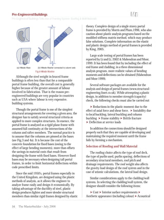
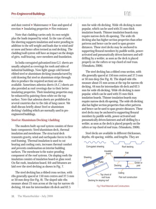
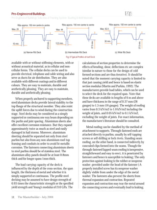
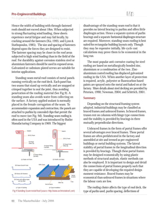
SlideShare a Scribd company logo
1 of 9
Download to read offline
48 The Masterbuilder - July 2008
Pre-Engineered Buildings
Selection of Framing System,
Roofing & Wall Materials
Pre-Engineered Buildings
Selection of Framing System,
Roofing & Wall Materials
Dr. N. Subramanian
Computer Design Consultants
Gaithersburg, MD 20878, USA
Introduction
High-rise steel buildings account for a very small
percentage of the total number of structures that are
built around the world. The majority of steel
structures being built are only low-rise buildings,
which are generally of one storey only. Industrial
buildings, a sub-set of low-rise buildings are normally
used for steel plants, automobile industries, light,
utility and process industries, thermal power stations,
warehouses, assembly plants, storage, garages, small
scale industries, etc. These buildings require large
column free areas. Hence interior columns, walls and
partitions are often eliminated or kept to a minimum.
Most of these buildings may require adequate
headroom for use of an overhead traveling crane. The
planning and design of these units require the
knowledge of the following items (Fisher 1984).
Site information Soil conditions. Plant
layout and work flow Preferred bay sizes Future
expansion plans Loading docks Crane types and
capacity Roofing, side cladding and wall material
preferences Heating, ventilation and air-
conditioning (HVAC) equipments loads Availability
of raw materials Availability of waste disposal and
sanitary facilities Parking facilities Preferred
fabricators/contractors Budget and project schedule.
The structural engineer has to consider the
following points (Fisher, 1984).
1) Selection of roofing and wall material
2) Selection of bay width 3) Selection of structural
framing system 4) Roof trusses 5) Purlins, girts and
sag rods. 6) Bracing systems to resist lateral loads
7) Gantry girders, columns, base plates and
foundations
We shall confine our attention to the selection of
framing system and selection of roofing and wall
material in this article. Details about other points
may be found in Subramanian (2008).
Structural Framing
For the purpose of structural analysis and design,
industrial buildings are classified as
Braced frames Unbraced frames.
In braced buildings, the trusses rest on columns
with hinge type of connections and the stability is
provided by the following bracings in the three
mutually perpendicular planes:
(a) bracings in vertical plane in the end bays in the
longitudinal direction
(b) bracings in horizontal plane at bottom chord level
of roof truss
(c) bracings in the plane of upper chords of roof truss
(d) bracings in vertical plane in the end cross sections
usually at the gable ends.
The function of bracing is to transfer horizontal
loads from the frames (such as those due to wind or
earthquake or horizontal surge due to acceleration and
breaking of traveling cranes) to the foundation. The
longitudinal bracing on each longitudinal ends provide
stability in the longitudinal direction. The gable
bracings provide stability in the lateral direction. The
tie bracings at the bottom chord level transfer lateral
loads (due to wind or earthquake) of trusses to the end
gable bracings.
Pre-Engineered Buildings
49The Masterbuilder - July 2008
Similarly stability in the horizontal plane is
provided by
rafter bracing in the end bays which provide
stability to trusses in their planes A bracing system
in the level of bottom chords of trusses, which
provide stability to the bottom chords of the trusses.
Braced frames are efficient in resisting the loads
and do not sway. However, the braces introduce
obstructions in some bays and may cause higher
forces or uplift forces in some places. Hence unbraced
frames are now-a-days preferred. Such unbraced
frames are often designed, prefabricated, and supplied
and erected at site by firms and are called pre-
engineered buildings or metal building systems. Many
companies are there India through whom we can
order these buildings
Pre-Engineered Buildings
Unbraced frames are in the form of portal frames
and are distinguished by their simplicity, clean lines
and economy. The frames can provide large column
free areas, offering maximum adaptability of the
space inside the building. Such large span buildings
require less foundation, and eliminate internal
columns, valley gutters and internal drainage. Portal
frame buildings offer many advantage such as more
effective use of steel than in simple beams, easy
extension at any time in the future and ability to
Fig1.TypicalPre-engineeredBuildingConstruction
Pre-Engineered Buildings
Pre-Engineered Buildings Selection of Framing System, Roofing & Wall Materials
LiuGong India Pvt. Ltd.
50 The Masterbuilder - July 2008
support heavy concentrated loads. The disadvantages
include relatively high material unit cost and
susceptibility to differential settlement and
temperature stresses. In addition, these frames
produce horizontal reaction on the foundation, which
may be resisted by providing a long tie beam or by
designing the foundation for this horizontal reaction.
Basically, a portal frame is a rigid jointed plane
frame made from hot-rolled or cold-rolled sections,
supporting the roofing and side cladding via hot rolled
or cold-formed purlins and sheeting rails (See Fig. 1).
The basic structural form of portal frames was
developed during the Second World War. The typical
span of portal frames is in the range of 30-40 m,
though they have been used in 15 to 80m, spans.
However, it is worthwhile considering the use of
multi-bay structures beyond 40 m span. The bay
spacing of portal frame may vary from 4.5 to 10 m
(typical bay spacing is 6 m). The eave height in
normal industrial building is about 4.5 m to 6.0 m
(which corresponds to the maximum height of one
level of sprinklers for fire protection). The ideal slope
for portal frame roofs probably lies between 19 and
30°, depending on the dimensions of the building and
wind permeability. The slope may be varied in design
to obtain minimum loading depending on the wind
permeability of the building sides and roofs.
Recent portal frames have a roof slope of from 6
to 12°, mainly chosen because of the smaller
volume of air involved in heating/cooling the
building. But in such cases, frame horizontal
deflections must be carefully checked and proper
foundations should be provided to take care of the
large horizontal thrust. Usually, the portal frames
Fig.2Typical Haunched Portal Frame
Fig.3Simpleunhaunchedportalframe
Fig.4TypicalDetailsandErectionofPre-EngineeredBuildings(Source:http://www.excelbuildings.com/site/790508/page/905273)
Pre-Engineered Buildings
Pre-Engineered Buildings Selection of Framing System, Roofing & Wall Materials
52 The Masterbuilder - July 2008
Fig.5SolidWeb,CastellatedandlatticeRafters
are composed of tapered stanchions and rafters (See
Fig.1) in order to provide an economic solution for
single-storey buildings. Portal frames made of
lattice members using angles or tubes are also
common, especially for covering long spans. The
most common form of portal frame used is the
pinned-base frame with different rafter and column
member size and with haunches at both the eaves
and apex connections (see Fig.2). The simple
unhaunched portal frame, its connections, and
erection are shown in Figs.3 and 4.
Using a solid-web rafter for the portal frame, has the
disadvantageofplacingpipesandconduitsbelowthe
bottom flange. This problem may be overcome by
adopting castellated or lattice rafters as shown in Fig. 5).
The lateral stability parallel to the portal frame is
provided by the frame itself. However, to resist the
loads perpendicular to the portal frame, wall and roof
bracings have to be provided as shown in Fig. 1. The
roof bracings, which may be in the form of diagonal
steel rods, are placed below the purlins for simplicity.
These diagonal rods and the rafters of the primary
portal frames constitute a horizontal truss and is some
times termed as roof diaphragm. The secondary
framing-wall grits and roof purlins-collects the load
from the wall and roof covering and distributes them
to the main portal frames and at the same time provides
lateral restraint to the members of portal frame.
The end frame or gables of a portal frame can be
framed in two different ways. They can be formed
using a frame identical to the intermediate portals
and then framing the gable or end posts up to the
underside of the portal rafter. Suitable arrangements
must be made at the post/rafter connections to
accommodate vertical movement of the portal rafter
(Dowling et al 1988). This method of gable framing
may be economical, if the building might be extended
in the future. When there is no scope for extension,
the gable rafter can be designed as a continuous
member, spanning between gable or end posts (as
shown in Fig. 1). This form of gable framing has poor
sway resistance and hence needs in-plane bracing. The
gable posts are generally designed as propped
cantilevers. They support the gable sheeting which are
subjected to wind loads; they sometimes support
secondary steel work for doors, openings, etc.
For buildings without cranes, the choice of
column type and orientation depends primarily on
building height, the wall system and the lateral load
carrying system. In general, wide-flange columns
provide most economical choice for exterior
columns in the buildings. This is particularly true
for rigid frames where rigid frame action is required
in one direction and girts are used to brace the weak
axis of these columns.
The lateral loads are transmitted along the wall
from brace to brace by eave strut. The eave struts are
designed for axial compression or for combined axial
compression and biaxial bending. The diagonal wall
bracing in the form of a rod may be attached to the
column through the hillside washer, which is a cast
circular element with a vertically slotted hole that
allows for variable angles of rod insertion (Newman,
2004). A matching vertically slotted hole is made in
the column web (see Fig.6).
Pre-Engineered Buildings
Pre-Engineered Buildings Selection of Framing System, Roofing & Wall Materials
54 The Masterbuilder - July 2008
Fig.6 Hillside Washer
Although the steel weight in braced frame
buildings is often less than that for a comparable
portal frame building, the overall cost is generally
higher because of the greater amount of labour
involved in fabrication. That is the reason pre-
engineered buildings are very popular in countries
such as USA where labour is very expensive.
building systems.
Though the portal frame is one of the simplest
structural arrangements for covering a given area, the
designer has to satisfy several structural criteria as
applied to more complex structures. In essence, the
portal frame is analysed as a rigid plane frame with
assumed full continuity at the intersections of the
column and rafter members. The normal practice is
to assume that the columns are pinned at the bases
(see Fig.3 and 4a). It is because the cost of the
concrete foundation for fixed bases (owing to the
effect of large bending moments), more than offsets
the savings in material costs that result from
designing the frame with fixed bases. However fixed
bases may be necessary when designing tall portal
frames, in order to limit horizontal deflections within
code prescribed limits.
Since the mid 1950's, portal frames especially in
the United Kingdom, are designed using the plastic
methods of analysis, as it allows the engineer to
analyze frame easily and design it economically. By
taking advantage of the ductility of steel, plastic
design produces lighter and more slender structural
members than similar rigid frames designed by elastic
theory. Complete design of a single storey portal
frame is provided by Morris and Plum,1996, who also
caution about plastic analysis programs based on the
modified stiffness matrix method, which may produce
false solutions. Complete information on the elastic
and plastic design method of portal frames is provided
by King, 2005.
Large scale testing of portal frames has been
reported by Li and Li, 2002 & Mahendran and Moor,
1999. It has been found that by including the effect of
end frame and cladding, in a three dimensional
analysis program, more realistic values of bending
moments and deflections can be obtained (Mahendran
and Moor 1999).
Several software packages are available for the
analysis and design of portal frames (www.structural-
engineering.fsnet.co.uk). While attempting a plastic
design, in addition to member strength (capacity)
check, the following checks must also be carried out
Reductions in the plastic moment due to the
effect of axial force and shear force. Instability due
to local buckling, lateral buckling and column
buckling Frame stability Brittle fracture
Deflection at service loads
In addition the connections should be designed
properly such that they are capable of developing and
maintaining the required moment until the frame
fails by forming a mechanism.
Selection of Roofing and Wall Material
The roofing choice affects the type of roof deck,
the type of purlin used, purlin spacing, deflections of
secondary structural members, roof pitch and
drainage requirements. The roof weight also affects
the gravity load design of the roof system and in the
case of seismic calculations, the lateral load design.
Similar considerations apply to the cladding/wall
systems. In selecting the cladding/wall system, the
designer should consider the following items:
Cost Interior surface requirements
Aesthetic appearance (including colour) Acoustical
Pre-Engineered Buildings
Pre-Engineered Buildings Selection of Framing System, Roofing & Wall Materials
56 The Masterbuilder - July 2008
and dust control Maintenance Ease and speed of
erection Insulating properties Fire resistance
Note that cladding carries only its own weight
plus the loads imposed by wind. In the case of roofs,
the sheeting supports insulation and water proofing in
addition to the self weight and loads due to wind and/
or snow and hence often termed as roof decking. The
cladding/wall system will have an impact on the design
of girts, wall bracing, eave members and foundation.
In India corrugated galvanized iron G.I. sheets are
usually adopted as coverings for roofs and sides of
industrial buildings. Now light-gauge cold formed
ribbed steel or aluminium decking (manufactured by
cold drawing flat steel or aluminium strips through
dies to produce the required section) are also
available. Sometimes asbestos sheets (A.C.) sheets are
also provided as roof coverings due to their better
insulating properties. Their insulating properties may
be enhanced by painting them white on the top
surface. Note that asbestos sheets are prohibited in
several countries due to the risk of lung cancer. We
shall discuss briefly about Steel or aluminium
decking/ cladding which are normally used in pre-
engineered buildings.
Steel or Aluminium Decking /cladding
The modern built-up roof system consists of three
basic components: Steel/aluminium deck, thermal
insulation and membrane. The structural deck
transmits gravity, wind and earthquake forces to the
roof framing. Thermal insulation is used to cut
heating and cooling costs, increases thermal comfort
and prevents condensation on interior building
surfaces. The membrane is the water-proofing
component of the roof systems. On sloping roofs the
insulation consists of insulation board or glass wool.
On flat roofs, insulation board, felt and bitumen are
laid over the steel decking as shown in Fig. 7.
The steel decking has a ribbed cross-section, with
ribs generally spaced at 150 mm centres and 37.5 mm
or 50 mm deep (See Fig. 8). The sloped-side ribs
measure about 25 mm across at the top for narrow rib
decking, 44 mm for intermediate rib deck and 62.5
mm for wide rib decking. Wide rib decking is more
popular, which can be used with 25 mm thick
insulation boards. Thinner insulation boards may
require narrow deck rib opening. The wide rib
decking also has higher section properties than other
patterns and hence can be used to span greater
distances. These steel decks may be anchored to
supporting flexural members by puddle welds, power-
activated and pneumatically driven fasteners and self-
drilling by a welder, as soon as the deck is placed
properly on the rafters or top chord of roof truss.
(Vinnakota, 2006).
The steel decking has a ribbed cross-section, with
ribs generally spaced at 150 mm centres and 37.5 mm
or 50 mm deep (See Fig. 8). The sloped-side ribs
measure about 25 mm across at the top for narrow rib
decking, 44 mm for intermediate rib deck and 62.5
mm for wide rib decking. Wide rib decking is more
popular, which can be used with 25 mm thick
insulation boards. Thinner insulation boards may
require narrow deck rib opening. The wide rib decking
also has higher section properties than other patterns
and hence can be used to span greater distances. These
steel decks may be anchored to supporting flexural
members by puddle welds, power-activated and
pneumatically driven fasteners and self-drilling by a
welder, as soon as the deck is placed properly on the
rafters or top chord of roof truss. (Vinnakota, 2006).
Steel decks are available in different thicknesses,
depths, rib spacing, widths, and lengths. They are
Fig.7RoofMaterialsandConstructions
Pre-Engineered Buildings
Pre-Engineered Buildings Selection of Framing System, Roofing & Wall Materials
58 The Masterbuilder - July 2008
available with or without stiffening elements, with or
without acoustical material, as in cellular and non-
cellular forms. The cellular decks can be used to
provide electrical, telephone and cable wiring and also
serve as ducts for air distribution. They are also
available with different coatings and in different
colours. They are easy to maintain, durable and
aesthetically pleasing. They are easy to maintain,
durable and aesthetically pleasing.
When properly anchored to supporting members,
steel/aluminium decks provide lateral stability to the
top flange of the structural member. They also resist
the uplift forces due to wind during the construction
stage. Steel decks may be considered as a simply
supported or continuous one way beam depending on
the purlin and joist spacing. Aluminium sheets also
offer excellent corrosion resistance. But they expand
approximately twice as much as steel and easily
damaged in hail storms. Moreover, aluminium
sheeting should be separated not only from steel
purlins but also from any non-aluminium roof-top
framing and conduits in order to avoid bi-metallic
corrosion. The fasteners connecting aluminium sheets
to steel purlins should be of stainless steel. The
aluminium alloy panels should be at least 0.8mm
thick and for longer spans 1mm thick.
The load carrying capacity of the deck is
influenced by the depth of the cross-section, the span
length, the thickness of metal and whether it is
simply supported or continuous. The profile steel
decking may be assumed to have design strength of
0.93 times the characteristic strength or the specified
yield strength and Young's modulus of 210 GPa. The
Fig. 8Typical Profiles of roof Deck
calculations of section properties to determine the
effects of bending, shear, deflections etc are complex
(similar in nature to those for the design of cold
formed sections and are thus iterative). It should be
noted that the moment carrying capacity is limited to
that just causing yield and hence is based on elastic
section modulus (Martin and Purkiss, 1992). The
manufacturers provide load tables, which can be used
to select the deck for the required span. Note that
these decks are available in lengths of 6 m and above
and have thickness in the range of 0.37 mm (28
gauges) to 1.5 mm (16 gauges). The weight of roofing
varies from 0.3 kN/m2 to 1.0 kN/m2 including the
weight of joists, and 0.05 kN/m2 to 0.1 kN/m2,
excluding the weight of joists. For exact information,
the manufacturer's literature should be consulted.
Metal roofing can be classified by the method of
attachment to supports. Through-fastened roofs are
attached directly to purlins, usually by self-tapping
screws or self-drilling or lock rivets. Standing-seam
roofing, on the other hand, is connected indirectly by
concealed clips formed into the seams. Though the
through-fastened lapped-seam roofing is inexpensive,
straightforward and easy to erect, it is penetrated by
fasteners and hence is susceptible to leaking; The only
protection against leaking is the rubber or neoprene
washer provided under the head of the fastener ( A
properly installed screw has its neoprene washer
slightly visible from under the edge of the metal
washer. The fasteners also prevent the sheets from
thermal expansion and contraction. Repeated
expansion and contraction may tear the metal around
the connecting screws and eventually lead to leaking.
Pre-Engineered Buildings
Pre-Engineered Buildings Selection of Framing System, Roofing & Wall Materials
60 The Masterbuilder - July 2008
Hence the width of building with through-fastened
roofs should not exceed about 18m. When subjected
to strong fluctuating wind loading, these sheets
experience metal fatigue and may fail locally, by
cracking around the fasteners (Xu, 1995; and Lynn &
Stathopoulos, 1985). The size and spacing of fasteners
depend upon the forces they are designed to resist.
The fastener spacing may be closer in the roof areas
subjected to high wind loading than in the field of the
roof. For durability against corrosion stainless steel or
aluminium fasteners should be used in exposed areas.
Galvanized or cadmium-plated screws are suitable for
interior applications.
Standing-seam metal roof consists of metal panels
running vertically on the roof deck. Each panel has
two seams that stand up vertically and are snapped or
crimped together to seal the joint, thus avoiding
penetration of the roofing material (See Fig.9). A
standing seam also avoids water from collecting on
the surface. A factory applied sealant is normally
placed in the female corrugation of the seam. To
accommodate expansion and contraction, the panels are
attached to purlins by concealed clips that permit the
roof to move (see Fig. 9d). Standing-seam roofing is
often used in the USA and was introduced by Butler
Manufacturing Company in 1969. The biggest
disadvantage of the standing-seam roof is that it
provides no lateral bracing to purlins and offers little
diaphragm action. Hence a separate system of purlin
bracings and a separate horizontaldiaphragmstructure
are required. Moreover, standing-seam roofing is best
suited for rectangular building layouts only. Though
they may be expensive initially, life-cycle cost
calculations may prove them to be economical in the
long run.
The most popular anti-corrosive coating for steel
roofing are based on metallurgically bonded zinc,
aluminium or a combination of the two. Zinc-
aluminium coated roofing has displaced galvanized
roofing in the USA. When another layer of protection
is required, acrylic, polyester or fluorocarbon based
paints are sprayed onto the metal and baked on at the
factory. More details about steel decking are provided by
Petersen, 1990; Newman, 2004; and Schittich, 2001.
Summary
Depending on the structural framing system
adopted, industrial buildings may be classified as
braced frames and unbraced frames. In braced frames,
trusses rest on columns with hinge type connections
and the stability is provided by bracings in three
mutually perpendicular directions.
Unbraced frames in the form of portal frames offer
several advantages over braced frames. These portal
frames are often prefabricated in the factory and
assembled at site and termed as pre-engineered
buildings or metal building systems. The lateral
stability of portal frames in the longitudinal direction
is provided by bracings. Though these portal frames
may be designed economically by using plastic
methods of structural analysis, elastic methods can
also be employed. It is important to design and detail
the connections of portal frames properly such that
they are capable of developing the required design
moment resistance. Braced frames may be
economical than unbraced frames in situations where
the labour costs are low.
The roofing choice affects the type of roof deck, the
type of purlin used, purlin spacing, deflections ofFig.9Standing-SeammetalRoof(source:http://www.archmetalroof.com)
Pre-Engineered Buildings
Pre-Engineered Buildings Selection of Framing System, Roofing & Wall Materials
62 The Masterbuilder - July 2008
secondary structural members, roof pitch and drainage
requirements. Steel or aluminium decking/ cladding are
normally used in pre-engineered buildings. Steel decks
are available in different thicknesses, depths, rib
spacing, widths, lengths, and colours. Though the
through-fastened lapped-seam roofing is inexpensive,
straightforward and easy to erect, it is penetrated by
fasteners and hence is susceptible to leaking. Hence
Standing-seam metal roofs consisting of metal panels
running vertically on the roof deck are used in present
day constructions. In standing-seam roofs, each panel
has two seams that stand up vertically and are snapped
or crimped together to seal the joint, thus avoiding
penetration of the roofing material.
References
Diaphragm Design Manual, Steel Deck Institute, Fox River Grove, IL, 1995.
Dowling, P.J., Knowles, P., and Owens, G.W. Structural Steel Design, The Steel
Construction Institute and Butterworths, London, 1988.
Fisher, J.M., Industrial buildings - guidelines and criteria, Engineering
Journal, AISC, Vol. 21, Third Quarter, 1984, pp. 149-153.
http://www.structural-engineering.fsnet.co.uk/free.htm (lists a number of free
structural software packages).
King, C.M., Design of Steel Portal frames for Europe, Steel Construction
Institute, Ascot, 2005.
Li, J-J., and Li, G-Q, Large scale testing of steel portal frames comprising
tapered beams and columns, Advances in Structural Engineering, Vol. 5, No.
4, Oct. 2002, pp. 259-269.
Lynn, B.A., and Stathopoulos, Wind induced fatigue on low metal buildings,
Journal of Structural Engineering, ASCE, Vol. 111, No. 4, April 1985, pp. 826-839.
Mahendran, M. and Moor, C., Three-dimensional modeling of steel portal
frame buildings, Journal of Structural Engineering, ASCE, Vol. 125, No.8, Aug.
1999, pp. 870-878.
Martin, L.H., and Purkiss, J.A., Structural Design of Steelwork to BS 5950,
Edward Arnold, London, 1992.
Morris, L.J., and Plum, D.R., Structural Steelwork Design to BS5950, Second
edition, Addison Wesley Longman, Essex, 1996.
Newman, A., Metal Building Systems: Design and Specifications, Second
edition, McGraw-Hill, New York, 2004, 576 pp.
Petersen, C., Stahlbau, Friedr. Vieweg & Sohn Verlag, Braunschweig, 1990,
(Chapter 17, Trapezprofil-Bauweise, pp. 719-745).
Schittich, C., In detail: Building Skins, Concepts, Layers, Materials, Birkhouser,
Switzerland, 2001, 120 pp.
Standard Specifications for Open Web Steel Joists. K-Series, Steel Joist
Institute, 41st edition, Myrtle Beach, SC, 2002.
Subramanian, N., Design of Steel Structures, Oxford University Press, New
Delhi, 2008, 1240pp.
Vinnakota, S., Steel Structures: Behavior & LRFD, McGraw-Hill Higher
Education, New York, 2006.
Xu,Y.L., Fatigue performance of screw-fastened light-gauge steel roof sheets,
Journal of Structural Engineering, ASCE, Vol. 121, No. 3, March 1995, pp.
389-398 also Discussions, Vol.122, No. 12, Dec. 1996, pp. 1475-1483.
Pre-Engineered Buildings
Pre-Engineered Buildings Selection of Framing System, Roofing & Wall Materials
Zed Enterprise Co.

More Related Content

What's hot

TYPES OF PILE FOUNDATION & APPLICATIONS
TYPES OF PILE FOUNDATION & APPLICATIONSTYPES OF PILE FOUNDATION & APPLICATIONS
TYPES OF PILE FOUNDATION & APPLICATIONSMaharshi Dave
 
Soils properties and foundations
Soils properties and foundations Soils properties and foundations
Soils properties and foundations ARUN KUMAR
 
Introduction to prestressed concrete
Introduction to prestressed concreteIntroduction to prestressed concrete
Introduction to prestressed concrete9833356555
 
Raft foundation ppt by kamal bhatia
Raft foundation ppt by kamal bhatiaRaft foundation ppt by kamal bhatia
Raft foundation ppt by kamal bhatiakamal bhatia
 
DEEP FOUNDATION
DEEP FOUNDATIONDEEP FOUNDATION
DEEP FOUNDATIONaframawal
 
PRECAST BUILDING SYSTEM
PRECAST BUILDING SYSTEMPRECAST BUILDING SYSTEM
PRECAST BUILDING SYSTEMSagar Shah
 
115659118 pre-engineered-buildings
115659118 pre-engineered-buildings115659118 pre-engineered-buildings
115659118 pre-engineered-buildingshlksd
 
Pre stressed concrete construction
Pre stressed concrete constructionPre stressed concrete construction
Pre stressed concrete constructionJenilPatel22
 
Type of structural joints
Type of structural joints Type of structural joints
Type of structural joints Hanzlahakhlaq
 
Temporary structures
Temporary structuresTemporary structures
Temporary structuresDivya Vishnoi
 
Combined & Eccentric Footing
Combined & Eccentric FootingCombined & Eccentric Footing
Combined & Eccentric FootingParth Patil
 
Precast construction
Precast constructionPrecast construction
Precast constructionDivya Vishnoi
 
Large span structures
Large span structuresLarge span structures
Large span structuresaduiti
 
Portal frame 1
Portal  frame 1Portal  frame 1
Portal frame 1Est
 

What's hot (20)

TYPES OF PILE FOUNDATION & APPLICATIONS
TYPES OF PILE FOUNDATION & APPLICATIONSTYPES OF PILE FOUNDATION & APPLICATIONS
TYPES OF PILE FOUNDATION & APPLICATIONS
 
Soils properties and foundations
Soils properties and foundations Soils properties and foundations
Soils properties and foundations
 
Introduction to prestressed concrete
Introduction to prestressed concreteIntroduction to prestressed concrete
Introduction to prestressed concrete
 
Steel Structure
Steel StructureSteel Structure
Steel Structure
 
Raft foundation ppt by kamal bhatia
Raft foundation ppt by kamal bhatiaRaft foundation ppt by kamal bhatia
Raft foundation ppt by kamal bhatia
 
DEEP FOUNDATION
DEEP FOUNDATIONDEEP FOUNDATION
DEEP FOUNDATION
 
PRECAST BUILDING SYSTEM
PRECAST BUILDING SYSTEMPRECAST BUILDING SYSTEM
PRECAST BUILDING SYSTEM
 
Arches
ArchesArches
Arches
 
Shear walls
Shear wallsShear walls
Shear walls
 
115659118 pre-engineered-buildings
115659118 pre-engineered-buildings115659118 pre-engineered-buildings
115659118 pre-engineered-buildings
 
Pre stressed concrete construction
Pre stressed concrete constructionPre stressed concrete construction
Pre stressed concrete construction
 
Type of structural joints
Type of structural joints Type of structural joints
Type of structural joints
 
Precast concrete structures
Precast concrete structuresPrecast concrete structures
Precast concrete structures
 
Temporary structures
Temporary structuresTemporary structures
Temporary structures
 
Combined & Eccentric Footing
Combined & Eccentric FootingCombined & Eccentric Footing
Combined & Eccentric Footing
 
Precast construction
Precast constructionPrecast construction
Precast construction
 
Large span structures
Large span structuresLarge span structures
Large span structures
 
Portal frame 1
Portal  frame 1Portal  frame 1
Portal frame 1
 
Slabs and types
Slabs and typesSlabs and types
Slabs and types
 
Deep foundation - pile foundation
Deep foundation - pile foundationDeep foundation - pile foundation
Deep foundation - pile foundation
 

Similar to Pre enginnered buildings master-builder_july08, pp.48-62

Industrial construction
Industrial constructionIndustrial construction
Industrial constructionCharlie Gupta
 
08 - Portal Frame.pptx
08 - Portal Frame.pptx08 - Portal Frame.pptx
08 - Portal Frame.pptx2022786965
 
Paper id 25201485
Paper id 25201485Paper id 25201485
Paper id 25201485IJRAT
 
Paper id 252014109
Paper id 252014109Paper id 252014109
Paper id 252014109IJRAT
 
115659118 pre-engineered-buildings (1)
115659118 pre-engineered-buildings (1)115659118 pre-engineered-buildings (1)
115659118 pre-engineered-buildings (1)hlksd
 
115659118 pre-engineered-buildings
115659118 pre-engineered-buildings115659118 pre-engineered-buildings
115659118 pre-engineered-buildingshlksd
 
Analysis of Multi-Storey Steel Structure with Different Infills and Steel Bra...
Analysis of Multi-Storey Steel Structure with Different Infills and Steel Bra...Analysis of Multi-Storey Steel Structure with Different Infills and Steel Bra...
Analysis of Multi-Storey Steel Structure with Different Infills and Steel Bra...IRJET Journal
 
TECH_SEMINAR_sachith_gowda[1].pptx
TECH_SEMINAR_sachith_gowda[1].pptxTECH_SEMINAR_sachith_gowda[1].pptx
TECH_SEMINAR_sachith_gowda[1].pptxChandanLawrence
 
Seismic Response of Structure with Single Core
Seismic Response of Structure with Single CoreSeismic Response of Structure with Single Core
Seismic Response of Structure with Single Coreijtsrd
 
Pre - Engineered Metal Buildings - The Latest Trend In Building construction
Pre - Engineered Metal Buildings - The Latest Trend In Building constructionPre - Engineered Metal Buildings - The Latest Trend In Building construction
Pre - Engineered Metal Buildings - The Latest Trend In Building constructionmustafa hussain
 
Pre engineered metal buildings - the latest trend in building construction
Pre   engineered metal buildings - the latest trend in building constructionPre   engineered metal buildings - the latest trend in building construction
Pre engineered metal buildings - the latest trend in building constructionhlksd
 
Pre - Engineered Metal Buildings - The Latest Trend In Building construction
Pre - Engineered Metal Buildings - The Latest Trend In Building constructionPre - Engineered Metal Buildings - The Latest Trend In Building construction
Pre - Engineered Metal Buildings - The Latest Trend In Building constructionmustafa hussain
 
Lecture 9 s.s.iii Design of Steel Structures - Faculty of Civil Engineering Iaşi
Lecture 9 s.s.iii Design of Steel Structures - Faculty of Civil Engineering IaşiLecture 9 s.s.iii Design of Steel Structures - Faculty of Civil Engineering Iaşi
Lecture 9 s.s.iii Design of Steel Structures - Faculty of Civil Engineering IaşiUrsachi Răzvan
 
Earthquake F.M.Bahlol
Earthquake F.M.BahlolEarthquake F.M.Bahlol
Earthquake F.M.BahlolFahadBahlol
 

Similar to Pre enginnered buildings master-builder_july08, pp.48-62 (20)

Industrial construction
Industrial constructionIndustrial construction
Industrial construction
 
08 - Portal Frame.pptx
08 - Portal Frame.pptx08 - Portal Frame.pptx
08 - Portal Frame.pptx
 
Guida ARBED edifici alti
Guida ARBED edifici altiGuida ARBED edifici alti
Guida ARBED edifici alti
 
Roof trusses
Roof trussesRoof trusses
Roof trusses
 
Industrial buildings
Industrial buildingsIndustrial buildings
Industrial buildings
 
Matkon_S.06.a_-_Portal_MKLW.pdf
Matkon_S.06.a_-_Portal_MKLW.pdfMatkon_S.06.a_-_Portal_MKLW.pdf
Matkon_S.06.a_-_Portal_MKLW.pdf
 
Paper id 25201485
Paper id 25201485Paper id 25201485
Paper id 25201485
 
Paper id 252014109
Paper id 252014109Paper id 252014109
Paper id 252014109
 
Rigid frame systems
Rigid frame systemsRigid frame systems
Rigid frame systems
 
115659118 pre-engineered-buildings (1)
115659118 pre-engineered-buildings (1)115659118 pre-engineered-buildings (1)
115659118 pre-engineered-buildings (1)
 
115659118 pre-engineered-buildings
115659118 pre-engineered-buildings115659118 pre-engineered-buildings
115659118 pre-engineered-buildings
 
Analysis of Multi-Storey Steel Structure with Different Infills and Steel Bra...
Analysis of Multi-Storey Steel Structure with Different Infills and Steel Bra...Analysis of Multi-Storey Steel Structure with Different Infills and Steel Bra...
Analysis of Multi-Storey Steel Structure with Different Infills and Steel Bra...
 
TECH_SEMINAR_sachith_gowda[1].pptx
TECH_SEMINAR_sachith_gowda[1].pptxTECH_SEMINAR_sachith_gowda[1].pptx
TECH_SEMINAR_sachith_gowda[1].pptx
 
Seismic Response of Structure with Single Core
Seismic Response of Structure with Single CoreSeismic Response of Structure with Single Core
Seismic Response of Structure with Single Core
 
BUILDING TECH 5_04.pptx
BUILDING TECH 5_04.pptxBUILDING TECH 5_04.pptx
BUILDING TECH 5_04.pptx
 
Pre - Engineered Metal Buildings - The Latest Trend In Building construction
Pre - Engineered Metal Buildings - The Latest Trend In Building constructionPre - Engineered Metal Buildings - The Latest Trend In Building construction
Pre - Engineered Metal Buildings - The Latest Trend In Building construction
 
Pre engineered metal buildings - the latest trend in building construction
Pre   engineered metal buildings - the latest trend in building constructionPre   engineered metal buildings - the latest trend in building construction
Pre engineered metal buildings - the latest trend in building construction
 
Pre - Engineered Metal Buildings - The Latest Trend In Building construction
Pre - Engineered Metal Buildings - The Latest Trend In Building constructionPre - Engineered Metal Buildings - The Latest Trend In Building construction
Pre - Engineered Metal Buildings - The Latest Trend In Building construction
 
Lecture 9 s.s.iii Design of Steel Structures - Faculty of Civil Engineering Iaşi
Lecture 9 s.s.iii Design of Steel Structures - Faculty of Civil Engineering IaşiLecture 9 s.s.iii Design of Steel Structures - Faculty of Civil Engineering Iaşi
Lecture 9 s.s.iii Design of Steel Structures - Faculty of Civil Engineering Iaşi
 
Earthquake F.M.Bahlol
Earthquake F.M.BahlolEarthquake F.M.Bahlol
Earthquake F.M.Bahlol
 

More from hlksd

Write better essays in 20 minutes a day
Write better essays in 20 minutes a dayWrite better essays in 20 minutes a day
Write better essays in 20 minutes a dayhlksd
 
Research and writing skills success in 20 minutes a day
Research and writing skills success in 20 minutes a dayResearch and writing skills success in 20 minutes a day
Research and writing skills success in 20 minutes a dayhlksd
 
Reasonskills
ReasonskillsReasonskills
Reasonskillshlksd
 
R05420107 advancedcommunicationskills
R05420107 advancedcommunicationskillsR05420107 advancedcommunicationskills
R05420107 advancedcommunicationskillshlksd
 
Proofreading revising editing skills success in 20 minutes a day
Proofreading revising editing skills success in 20 minutes a dayProofreading revising editing skills success in 20 minutes a day
Proofreading revising editing skills success in 20 minutes a dayhlksd
 
R05420107 advanced-communication-skills
R05420107 advanced-communication-skillsR05420107 advanced-communication-skills
R05420107 advanced-communication-skillshlksd
 
Tuladhar
TuladharTuladhar
Tuladharhlksd
 
Standard specifications
Standard specificationsStandard specifications
Standard specificationshlksd
 
Presentation by gursharan singh for engineeringcivil.com
Presentation by gursharan singh for engineeringcivil.comPresentation by gursharan singh for engineeringcivil.com
Presentation by gursharan singh for engineeringcivil.comhlksd
 
Pre engineered buildings
Pre engineered buildingsPre engineered buildings
Pre engineered buildingshlksd
 
Pre engg buildings
Pre engg buildingsPre engg buildings
Pre engg buildingshlksd
 
Pebvsconvsteel
PebvsconvsteelPebvsconvsteel
Pebvsconvsteelhlksd
 
Peb structures (1)
Peb structures (1)Peb structures (1)
Peb structures (1)hlksd
 
Peb structures
Peb structuresPeb structures
Peb structureshlksd
 
As22267272
As22267272As22267272
As22267272hlksd
 
96382022 pre-engineered-buildings
96382022 pre-engineered-buildings96382022 pre-engineered-buildings
96382022 pre-engineered-buildingshlksd
 
101804898 project-report-of-pre-engineered-steel-building
101804898 project-report-of-pre-engineered-steel-building101804898 project-report-of-pre-engineered-steel-building
101804898 project-report-of-pre-engineered-steel-buildinghlksd
 
101804898 project-report-of-pre-engineered-steel-building
101804898 project-report-of-pre-engineered-steel-building101804898 project-report-of-pre-engineered-steel-building
101804898 project-report-of-pre-engineered-steel-buildinghlksd
 
88254718 pre-–engineered-steel-buildings
88254718 pre-–engineered-steel-buildings88254718 pre-–engineered-steel-buildings
88254718 pre-–engineered-steel-buildingshlksd
 

More from hlksd (20)

Write better essays in 20 minutes a day
Write better essays in 20 minutes a dayWrite better essays in 20 minutes a day
Write better essays in 20 minutes a day
 
Research and writing skills success in 20 minutes a day
Research and writing skills success in 20 minutes a dayResearch and writing skills success in 20 minutes a day
Research and writing skills success in 20 minutes a day
 
Reasonskills
ReasonskillsReasonskills
Reasonskills
 
R05420107 advancedcommunicationskills
R05420107 advancedcommunicationskillsR05420107 advancedcommunicationskills
R05420107 advancedcommunicationskills
 
Proofreading revising editing skills success in 20 minutes a day
Proofreading revising editing skills success in 20 minutes a dayProofreading revising editing skills success in 20 minutes a day
Proofreading revising editing skills success in 20 minutes a day
 
R05420107 advanced-communication-skills
R05420107 advanced-communication-skillsR05420107 advanced-communication-skills
R05420107 advanced-communication-skills
 
Tuladhar
TuladharTuladhar
Tuladhar
 
Standard specifications
Standard specificationsStandard specifications
Standard specifications
 
Presentation by gursharan singh for engineeringcivil.com
Presentation by gursharan singh for engineeringcivil.comPresentation by gursharan singh for engineeringcivil.com
Presentation by gursharan singh for engineeringcivil.com
 
Pre engineered buildings
Pre engineered buildingsPre engineered buildings
Pre engineered buildings
 
Pre engg buildings
Pre engg buildingsPre engg buildings
Pre engg buildings
 
Pebvsconvsteel
PebvsconvsteelPebvsconvsteel
Pebvsconvsteel
 
Peb
PebPeb
Peb
 
Peb structures (1)
Peb structures (1)Peb structures (1)
Peb structures (1)
 
Peb structures
Peb structuresPeb structures
Peb structures
 
As22267272
As22267272As22267272
As22267272
 
96382022 pre-engineered-buildings
96382022 pre-engineered-buildings96382022 pre-engineered-buildings
96382022 pre-engineered-buildings
 
101804898 project-report-of-pre-engineered-steel-building
101804898 project-report-of-pre-engineered-steel-building101804898 project-report-of-pre-engineered-steel-building
101804898 project-report-of-pre-engineered-steel-building
 
101804898 project-report-of-pre-engineered-steel-building
101804898 project-report-of-pre-engineered-steel-building101804898 project-report-of-pre-engineered-steel-building
101804898 project-report-of-pre-engineered-steel-building
 
88254718 pre-–engineered-steel-buildings
88254718 pre-–engineered-steel-buildings88254718 pre-–engineered-steel-buildings
88254718 pre-–engineered-steel-buildings
 

Pre enginnered buildings master-builder_july08, pp.48-62

  • 1. 48 The Masterbuilder - July 2008 Pre-Engineered Buildings Selection of Framing System, Roofing & Wall Materials Pre-Engineered Buildings Selection of Framing System, Roofing & Wall Materials Dr. N. Subramanian Computer Design Consultants Gaithersburg, MD 20878, USA Introduction High-rise steel buildings account for a very small percentage of the total number of structures that are built around the world. The majority of steel structures being built are only low-rise buildings, which are generally of one storey only. Industrial buildings, a sub-set of low-rise buildings are normally used for steel plants, automobile industries, light, utility and process industries, thermal power stations, warehouses, assembly plants, storage, garages, small scale industries, etc. These buildings require large column free areas. Hence interior columns, walls and partitions are often eliminated or kept to a minimum. Most of these buildings may require adequate headroom for use of an overhead traveling crane. The planning and design of these units require the knowledge of the following items (Fisher 1984). Site information Soil conditions. Plant layout and work flow Preferred bay sizes Future expansion plans Loading docks Crane types and capacity Roofing, side cladding and wall material preferences Heating, ventilation and air- conditioning (HVAC) equipments loads Availability of raw materials Availability of waste disposal and sanitary facilities Parking facilities Preferred fabricators/contractors Budget and project schedule. The structural engineer has to consider the following points (Fisher, 1984). 1) Selection of roofing and wall material 2) Selection of bay width 3) Selection of structural framing system 4) Roof trusses 5) Purlins, girts and sag rods. 6) Bracing systems to resist lateral loads 7) Gantry girders, columns, base plates and foundations We shall confine our attention to the selection of framing system and selection of roofing and wall material in this article. Details about other points may be found in Subramanian (2008). Structural Framing For the purpose of structural analysis and design, industrial buildings are classified as Braced frames Unbraced frames. In braced buildings, the trusses rest on columns with hinge type of connections and the stability is provided by the following bracings in the three mutually perpendicular planes: (a) bracings in vertical plane in the end bays in the longitudinal direction (b) bracings in horizontal plane at bottom chord level of roof truss (c) bracings in the plane of upper chords of roof truss (d) bracings in vertical plane in the end cross sections usually at the gable ends. The function of bracing is to transfer horizontal loads from the frames (such as those due to wind or earthquake or horizontal surge due to acceleration and breaking of traveling cranes) to the foundation. The longitudinal bracing on each longitudinal ends provide stability in the longitudinal direction. The gable bracings provide stability in the lateral direction. The tie bracings at the bottom chord level transfer lateral loads (due to wind or earthquake) of trusses to the end gable bracings. Pre-Engineered Buildings
  • 2. 49The Masterbuilder - July 2008 Similarly stability in the horizontal plane is provided by rafter bracing in the end bays which provide stability to trusses in their planes A bracing system in the level of bottom chords of trusses, which provide stability to the bottom chords of the trusses. Braced frames are efficient in resisting the loads and do not sway. However, the braces introduce obstructions in some bays and may cause higher forces or uplift forces in some places. Hence unbraced frames are now-a-days preferred. Such unbraced frames are often designed, prefabricated, and supplied and erected at site by firms and are called pre- engineered buildings or metal building systems. Many companies are there India through whom we can order these buildings Pre-Engineered Buildings Unbraced frames are in the form of portal frames and are distinguished by their simplicity, clean lines and economy. The frames can provide large column free areas, offering maximum adaptability of the space inside the building. Such large span buildings require less foundation, and eliminate internal columns, valley gutters and internal drainage. Portal frame buildings offer many advantage such as more effective use of steel than in simple beams, easy extension at any time in the future and ability to Fig1.TypicalPre-engineeredBuildingConstruction Pre-Engineered Buildings Pre-Engineered Buildings Selection of Framing System, Roofing & Wall Materials LiuGong India Pvt. Ltd.
  • 3. 50 The Masterbuilder - July 2008 support heavy concentrated loads. The disadvantages include relatively high material unit cost and susceptibility to differential settlement and temperature stresses. In addition, these frames produce horizontal reaction on the foundation, which may be resisted by providing a long tie beam or by designing the foundation for this horizontal reaction. Basically, a portal frame is a rigid jointed plane frame made from hot-rolled or cold-rolled sections, supporting the roofing and side cladding via hot rolled or cold-formed purlins and sheeting rails (See Fig. 1). The basic structural form of portal frames was developed during the Second World War. The typical span of portal frames is in the range of 30-40 m, though they have been used in 15 to 80m, spans. However, it is worthwhile considering the use of multi-bay structures beyond 40 m span. The bay spacing of portal frame may vary from 4.5 to 10 m (typical bay spacing is 6 m). The eave height in normal industrial building is about 4.5 m to 6.0 m (which corresponds to the maximum height of one level of sprinklers for fire protection). The ideal slope for portal frame roofs probably lies between 19 and 30°, depending on the dimensions of the building and wind permeability. The slope may be varied in design to obtain minimum loading depending on the wind permeability of the building sides and roofs. Recent portal frames have a roof slope of from 6 to 12°, mainly chosen because of the smaller volume of air involved in heating/cooling the building. But in such cases, frame horizontal deflections must be carefully checked and proper foundations should be provided to take care of the large horizontal thrust. Usually, the portal frames Fig.2Typical Haunched Portal Frame Fig.3Simpleunhaunchedportalframe Fig.4TypicalDetailsandErectionofPre-EngineeredBuildings(Source:http://www.excelbuildings.com/site/790508/page/905273) Pre-Engineered Buildings Pre-Engineered Buildings Selection of Framing System, Roofing & Wall Materials
  • 4. 52 The Masterbuilder - July 2008 Fig.5SolidWeb,CastellatedandlatticeRafters are composed of tapered stanchions and rafters (See Fig.1) in order to provide an economic solution for single-storey buildings. Portal frames made of lattice members using angles or tubes are also common, especially for covering long spans. The most common form of portal frame used is the pinned-base frame with different rafter and column member size and with haunches at both the eaves and apex connections (see Fig.2). The simple unhaunched portal frame, its connections, and erection are shown in Figs.3 and 4. Using a solid-web rafter for the portal frame, has the disadvantageofplacingpipesandconduitsbelowthe bottom flange. This problem may be overcome by adopting castellated or lattice rafters as shown in Fig. 5). The lateral stability parallel to the portal frame is provided by the frame itself. However, to resist the loads perpendicular to the portal frame, wall and roof bracings have to be provided as shown in Fig. 1. The roof bracings, which may be in the form of diagonal steel rods, are placed below the purlins for simplicity. These diagonal rods and the rafters of the primary portal frames constitute a horizontal truss and is some times termed as roof diaphragm. The secondary framing-wall grits and roof purlins-collects the load from the wall and roof covering and distributes them to the main portal frames and at the same time provides lateral restraint to the members of portal frame. The end frame or gables of a portal frame can be framed in two different ways. They can be formed using a frame identical to the intermediate portals and then framing the gable or end posts up to the underside of the portal rafter. Suitable arrangements must be made at the post/rafter connections to accommodate vertical movement of the portal rafter (Dowling et al 1988). This method of gable framing may be economical, if the building might be extended in the future. When there is no scope for extension, the gable rafter can be designed as a continuous member, spanning between gable or end posts (as shown in Fig. 1). This form of gable framing has poor sway resistance and hence needs in-plane bracing. The gable posts are generally designed as propped cantilevers. They support the gable sheeting which are subjected to wind loads; they sometimes support secondary steel work for doors, openings, etc. For buildings without cranes, the choice of column type and orientation depends primarily on building height, the wall system and the lateral load carrying system. In general, wide-flange columns provide most economical choice for exterior columns in the buildings. This is particularly true for rigid frames where rigid frame action is required in one direction and girts are used to brace the weak axis of these columns. The lateral loads are transmitted along the wall from brace to brace by eave strut. The eave struts are designed for axial compression or for combined axial compression and biaxial bending. The diagonal wall bracing in the form of a rod may be attached to the column through the hillside washer, which is a cast circular element with a vertically slotted hole that allows for variable angles of rod insertion (Newman, 2004). A matching vertically slotted hole is made in the column web (see Fig.6). Pre-Engineered Buildings Pre-Engineered Buildings Selection of Framing System, Roofing & Wall Materials
  • 5. 54 The Masterbuilder - July 2008 Fig.6 Hillside Washer Although the steel weight in braced frame buildings is often less than that for a comparable portal frame building, the overall cost is generally higher because of the greater amount of labour involved in fabrication. That is the reason pre- engineered buildings are very popular in countries such as USA where labour is very expensive. building systems. Though the portal frame is one of the simplest structural arrangements for covering a given area, the designer has to satisfy several structural criteria as applied to more complex structures. In essence, the portal frame is analysed as a rigid plane frame with assumed full continuity at the intersections of the column and rafter members. The normal practice is to assume that the columns are pinned at the bases (see Fig.3 and 4a). It is because the cost of the concrete foundation for fixed bases (owing to the effect of large bending moments), more than offsets the savings in material costs that result from designing the frame with fixed bases. However fixed bases may be necessary when designing tall portal frames, in order to limit horizontal deflections within code prescribed limits. Since the mid 1950's, portal frames especially in the United Kingdom, are designed using the plastic methods of analysis, as it allows the engineer to analyze frame easily and design it economically. By taking advantage of the ductility of steel, plastic design produces lighter and more slender structural members than similar rigid frames designed by elastic theory. Complete design of a single storey portal frame is provided by Morris and Plum,1996, who also caution about plastic analysis programs based on the modified stiffness matrix method, which may produce false solutions. Complete information on the elastic and plastic design method of portal frames is provided by King, 2005. Large scale testing of portal frames has been reported by Li and Li, 2002 & Mahendran and Moor, 1999. It has been found that by including the effect of end frame and cladding, in a three dimensional analysis program, more realistic values of bending moments and deflections can be obtained (Mahendran and Moor 1999). Several software packages are available for the analysis and design of portal frames (www.structural- engineering.fsnet.co.uk). While attempting a plastic design, in addition to member strength (capacity) check, the following checks must also be carried out Reductions in the plastic moment due to the effect of axial force and shear force. Instability due to local buckling, lateral buckling and column buckling Frame stability Brittle fracture Deflection at service loads In addition the connections should be designed properly such that they are capable of developing and maintaining the required moment until the frame fails by forming a mechanism. Selection of Roofing and Wall Material The roofing choice affects the type of roof deck, the type of purlin used, purlin spacing, deflections of secondary structural members, roof pitch and drainage requirements. The roof weight also affects the gravity load design of the roof system and in the case of seismic calculations, the lateral load design. Similar considerations apply to the cladding/wall systems. In selecting the cladding/wall system, the designer should consider the following items: Cost Interior surface requirements Aesthetic appearance (including colour) Acoustical Pre-Engineered Buildings Pre-Engineered Buildings Selection of Framing System, Roofing & Wall Materials
  • 6. 56 The Masterbuilder - July 2008 and dust control Maintenance Ease and speed of erection Insulating properties Fire resistance Note that cladding carries only its own weight plus the loads imposed by wind. In the case of roofs, the sheeting supports insulation and water proofing in addition to the self weight and loads due to wind and/ or snow and hence often termed as roof decking. The cladding/wall system will have an impact on the design of girts, wall bracing, eave members and foundation. In India corrugated galvanized iron G.I. sheets are usually adopted as coverings for roofs and sides of industrial buildings. Now light-gauge cold formed ribbed steel or aluminium decking (manufactured by cold drawing flat steel or aluminium strips through dies to produce the required section) are also available. Sometimes asbestos sheets (A.C.) sheets are also provided as roof coverings due to their better insulating properties. Their insulating properties may be enhanced by painting them white on the top surface. Note that asbestos sheets are prohibited in several countries due to the risk of lung cancer. We shall discuss briefly about Steel or aluminium decking/ cladding which are normally used in pre- engineered buildings. Steel or Aluminium Decking /cladding The modern built-up roof system consists of three basic components: Steel/aluminium deck, thermal insulation and membrane. The structural deck transmits gravity, wind and earthquake forces to the roof framing. Thermal insulation is used to cut heating and cooling costs, increases thermal comfort and prevents condensation on interior building surfaces. The membrane is the water-proofing component of the roof systems. On sloping roofs the insulation consists of insulation board or glass wool. On flat roofs, insulation board, felt and bitumen are laid over the steel decking as shown in Fig. 7. The steel decking has a ribbed cross-section, with ribs generally spaced at 150 mm centres and 37.5 mm or 50 mm deep (See Fig. 8). The sloped-side ribs measure about 25 mm across at the top for narrow rib decking, 44 mm for intermediate rib deck and 62.5 mm for wide rib decking. Wide rib decking is more popular, which can be used with 25 mm thick insulation boards. Thinner insulation boards may require narrow deck rib opening. The wide rib decking also has higher section properties than other patterns and hence can be used to span greater distances. These steel decks may be anchored to supporting flexural members by puddle welds, power- activated and pneumatically driven fasteners and self- drilling by a welder, as soon as the deck is placed properly on the rafters or top chord of roof truss. (Vinnakota, 2006). The steel decking has a ribbed cross-section, with ribs generally spaced at 150 mm centres and 37.5 mm or 50 mm deep (See Fig. 8). The sloped-side ribs measure about 25 mm across at the top for narrow rib decking, 44 mm for intermediate rib deck and 62.5 mm for wide rib decking. Wide rib decking is more popular, which can be used with 25 mm thick insulation boards. Thinner insulation boards may require narrow deck rib opening. The wide rib decking also has higher section properties than other patterns and hence can be used to span greater distances. These steel decks may be anchored to supporting flexural members by puddle welds, power-activated and pneumatically driven fasteners and self-drilling by a welder, as soon as the deck is placed properly on the rafters or top chord of roof truss. (Vinnakota, 2006). Steel decks are available in different thicknesses, depths, rib spacing, widths, and lengths. They are Fig.7RoofMaterialsandConstructions Pre-Engineered Buildings Pre-Engineered Buildings Selection of Framing System, Roofing & Wall Materials
  • 7. 58 The Masterbuilder - July 2008 available with or without stiffening elements, with or without acoustical material, as in cellular and non- cellular forms. The cellular decks can be used to provide electrical, telephone and cable wiring and also serve as ducts for air distribution. They are also available with different coatings and in different colours. They are easy to maintain, durable and aesthetically pleasing. They are easy to maintain, durable and aesthetically pleasing. When properly anchored to supporting members, steel/aluminium decks provide lateral stability to the top flange of the structural member. They also resist the uplift forces due to wind during the construction stage. Steel decks may be considered as a simply supported or continuous one way beam depending on the purlin and joist spacing. Aluminium sheets also offer excellent corrosion resistance. But they expand approximately twice as much as steel and easily damaged in hail storms. Moreover, aluminium sheeting should be separated not only from steel purlins but also from any non-aluminium roof-top framing and conduits in order to avoid bi-metallic corrosion. The fasteners connecting aluminium sheets to steel purlins should be of stainless steel. The aluminium alloy panels should be at least 0.8mm thick and for longer spans 1mm thick. The load carrying capacity of the deck is influenced by the depth of the cross-section, the span length, the thickness of metal and whether it is simply supported or continuous. The profile steel decking may be assumed to have design strength of 0.93 times the characteristic strength or the specified yield strength and Young's modulus of 210 GPa. The Fig. 8Typical Profiles of roof Deck calculations of section properties to determine the effects of bending, shear, deflections etc are complex (similar in nature to those for the design of cold formed sections and are thus iterative). It should be noted that the moment carrying capacity is limited to that just causing yield and hence is based on elastic section modulus (Martin and Purkiss, 1992). The manufacturers provide load tables, which can be used to select the deck for the required span. Note that these decks are available in lengths of 6 m and above and have thickness in the range of 0.37 mm (28 gauges) to 1.5 mm (16 gauges). The weight of roofing varies from 0.3 kN/m2 to 1.0 kN/m2 including the weight of joists, and 0.05 kN/m2 to 0.1 kN/m2, excluding the weight of joists. For exact information, the manufacturer's literature should be consulted. Metal roofing can be classified by the method of attachment to supports. Through-fastened roofs are attached directly to purlins, usually by self-tapping screws or self-drilling or lock rivets. Standing-seam roofing, on the other hand, is connected indirectly by concealed clips formed into the seams. Though the through-fastened lapped-seam roofing is inexpensive, straightforward and easy to erect, it is penetrated by fasteners and hence is susceptible to leaking; The only protection against leaking is the rubber or neoprene washer provided under the head of the fastener ( A properly installed screw has its neoprene washer slightly visible from under the edge of the metal washer. The fasteners also prevent the sheets from thermal expansion and contraction. Repeated expansion and contraction may tear the metal around the connecting screws and eventually lead to leaking. Pre-Engineered Buildings Pre-Engineered Buildings Selection of Framing System, Roofing & Wall Materials
  • 8. 60 The Masterbuilder - July 2008 Hence the width of building with through-fastened roofs should not exceed about 18m. When subjected to strong fluctuating wind loading, these sheets experience metal fatigue and may fail locally, by cracking around the fasteners (Xu, 1995; and Lynn & Stathopoulos, 1985). The size and spacing of fasteners depend upon the forces they are designed to resist. The fastener spacing may be closer in the roof areas subjected to high wind loading than in the field of the roof. For durability against corrosion stainless steel or aluminium fasteners should be used in exposed areas. Galvanized or cadmium-plated screws are suitable for interior applications. Standing-seam metal roof consists of metal panels running vertically on the roof deck. Each panel has two seams that stand up vertically and are snapped or crimped together to seal the joint, thus avoiding penetration of the roofing material (See Fig.9). A standing seam also avoids water from collecting on the surface. A factory applied sealant is normally placed in the female corrugation of the seam. To accommodate expansion and contraction, the panels are attached to purlins by concealed clips that permit the roof to move (see Fig. 9d). Standing-seam roofing is often used in the USA and was introduced by Butler Manufacturing Company in 1969. The biggest disadvantage of the standing-seam roof is that it provides no lateral bracing to purlins and offers little diaphragm action. Hence a separate system of purlin bracings and a separate horizontaldiaphragmstructure are required. Moreover, standing-seam roofing is best suited for rectangular building layouts only. Though they may be expensive initially, life-cycle cost calculations may prove them to be economical in the long run. The most popular anti-corrosive coating for steel roofing are based on metallurgically bonded zinc, aluminium or a combination of the two. Zinc- aluminium coated roofing has displaced galvanized roofing in the USA. When another layer of protection is required, acrylic, polyester or fluorocarbon based paints are sprayed onto the metal and baked on at the factory. More details about steel decking are provided by Petersen, 1990; Newman, 2004; and Schittich, 2001. Summary Depending on the structural framing system adopted, industrial buildings may be classified as braced frames and unbraced frames. In braced frames, trusses rest on columns with hinge type connections and the stability is provided by bracings in three mutually perpendicular directions. Unbraced frames in the form of portal frames offer several advantages over braced frames. These portal frames are often prefabricated in the factory and assembled at site and termed as pre-engineered buildings or metal building systems. The lateral stability of portal frames in the longitudinal direction is provided by bracings. Though these portal frames may be designed economically by using plastic methods of structural analysis, elastic methods can also be employed. It is important to design and detail the connections of portal frames properly such that they are capable of developing the required design moment resistance. Braced frames may be economical than unbraced frames in situations where the labour costs are low. The roofing choice affects the type of roof deck, the type of purlin used, purlin spacing, deflections ofFig.9Standing-SeammetalRoof(source:http://www.archmetalroof.com) Pre-Engineered Buildings Pre-Engineered Buildings Selection of Framing System, Roofing & Wall Materials
  • 9. 62 The Masterbuilder - July 2008 secondary structural members, roof pitch and drainage requirements. Steel or aluminium decking/ cladding are normally used in pre-engineered buildings. Steel decks are available in different thicknesses, depths, rib spacing, widths, lengths, and colours. Though the through-fastened lapped-seam roofing is inexpensive, straightforward and easy to erect, it is penetrated by fasteners and hence is susceptible to leaking. Hence Standing-seam metal roofs consisting of metal panels running vertically on the roof deck are used in present day constructions. In standing-seam roofs, each panel has two seams that stand up vertically and are snapped or crimped together to seal the joint, thus avoiding penetration of the roofing material. References Diaphragm Design Manual, Steel Deck Institute, Fox River Grove, IL, 1995. Dowling, P.J., Knowles, P., and Owens, G.W. Structural Steel Design, The Steel Construction Institute and Butterworths, London, 1988. Fisher, J.M., Industrial buildings - guidelines and criteria, Engineering Journal, AISC, Vol. 21, Third Quarter, 1984, pp. 149-153. http://www.structural-engineering.fsnet.co.uk/free.htm (lists a number of free structural software packages). King, C.M., Design of Steel Portal frames for Europe, Steel Construction Institute, Ascot, 2005. Li, J-J., and Li, G-Q, Large scale testing of steel portal frames comprising tapered beams and columns, Advances in Structural Engineering, Vol. 5, No. 4, Oct. 2002, pp. 259-269. Lynn, B.A., and Stathopoulos, Wind induced fatigue on low metal buildings, Journal of Structural Engineering, ASCE, Vol. 111, No. 4, April 1985, pp. 826-839. Mahendran, M. and Moor, C., Three-dimensional modeling of steel portal frame buildings, Journal of Structural Engineering, ASCE, Vol. 125, No.8, Aug. 1999, pp. 870-878. Martin, L.H., and Purkiss, J.A., Structural Design of Steelwork to BS 5950, Edward Arnold, London, 1992. Morris, L.J., and Plum, D.R., Structural Steelwork Design to BS5950, Second edition, Addison Wesley Longman, Essex, 1996. Newman, A., Metal Building Systems: Design and Specifications, Second edition, McGraw-Hill, New York, 2004, 576 pp. Petersen, C., Stahlbau, Friedr. Vieweg & Sohn Verlag, Braunschweig, 1990, (Chapter 17, Trapezprofil-Bauweise, pp. 719-745). Schittich, C., In detail: Building Skins, Concepts, Layers, Materials, Birkhouser, Switzerland, 2001, 120 pp. Standard Specifications for Open Web Steel Joists. K-Series, Steel Joist Institute, 41st edition, Myrtle Beach, SC, 2002. Subramanian, N., Design of Steel Structures, Oxford University Press, New Delhi, 2008, 1240pp. Vinnakota, S., Steel Structures: Behavior & LRFD, McGraw-Hill Higher Education, New York, 2006. Xu,Y.L., Fatigue performance of screw-fastened light-gauge steel roof sheets, Journal of Structural Engineering, ASCE, Vol. 121, No. 3, March 1995, pp. 389-398 also Discussions, Vol.122, No. 12, Dec. 1996, pp. 1475-1483. Pre-Engineered Buildings Pre-Engineered Buildings Selection of Framing System, Roofing & Wall Materials Zed Enterprise Co.