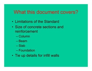
This document covers guidelines for non-engineered or pre-engineered buildings in Nepal, including:
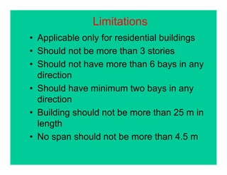
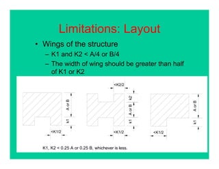
1. Limitations on building size, number of bays, and span lengths for pre-engineered designs.
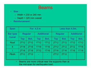
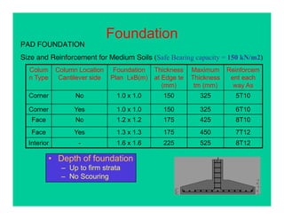
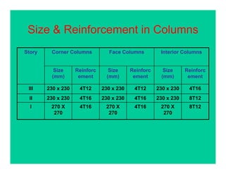
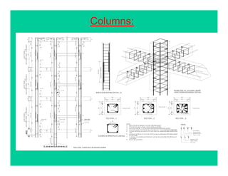
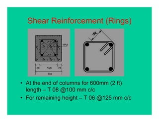
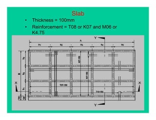
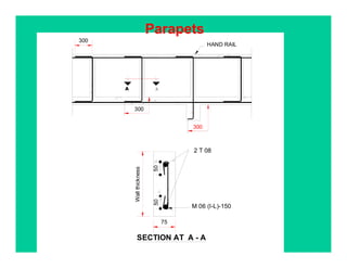
2. Details on sizing concrete sections and reinforcement for columns, beams, slabs, and foundations.
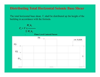
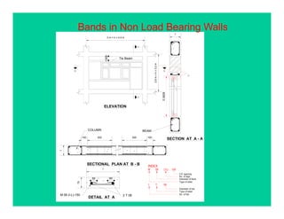
3. Requirements for tie reinforcement in infill walls and distributing seismic forces.
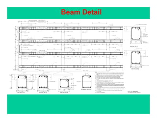
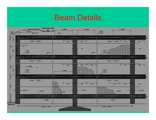
4. Examples of beam and column reinforcement details.