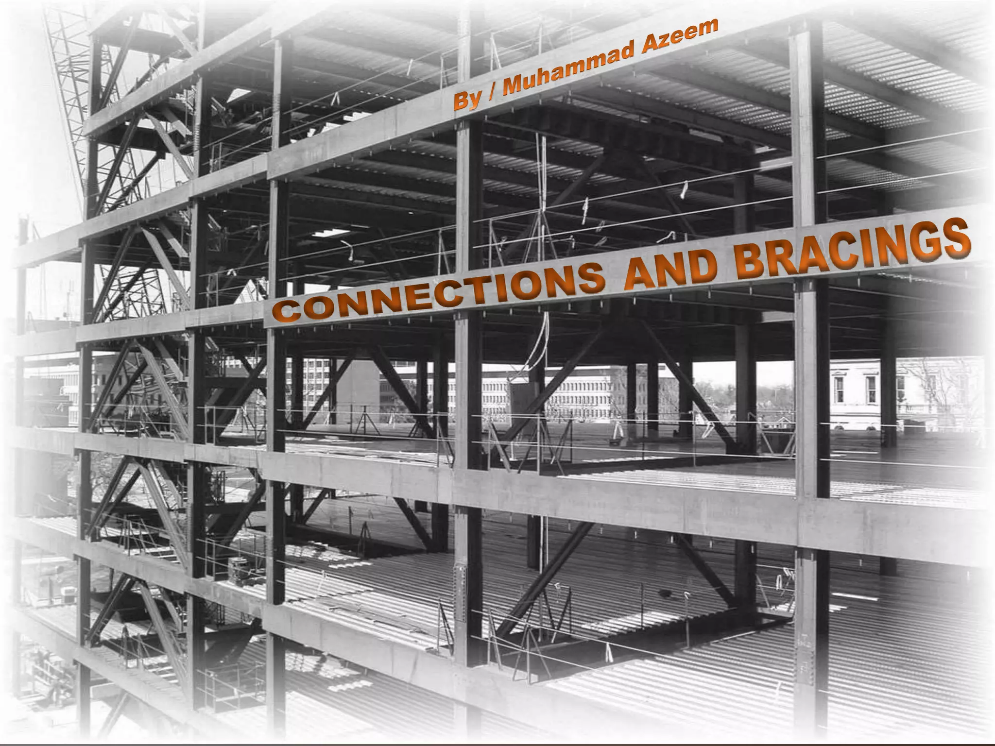
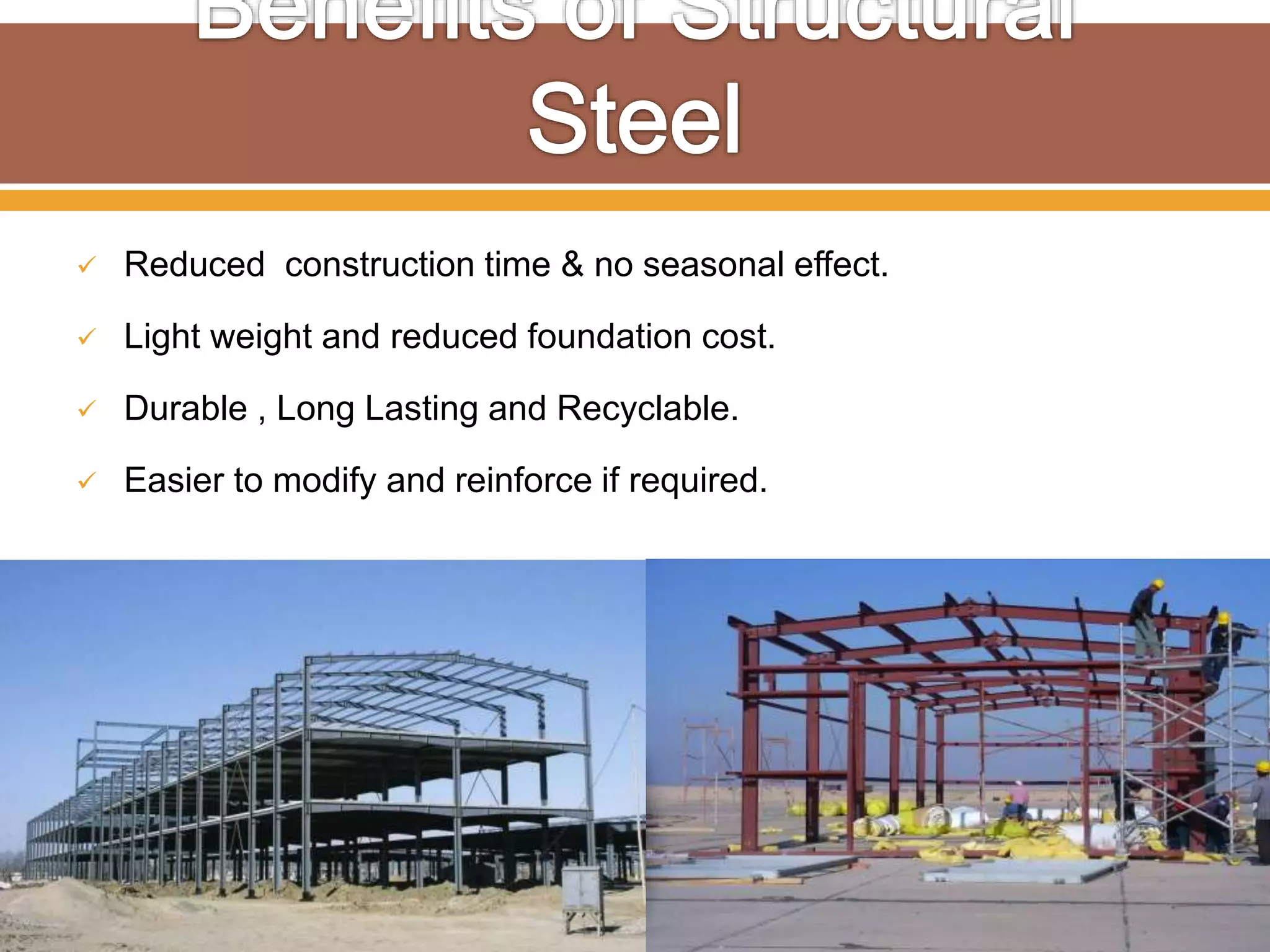
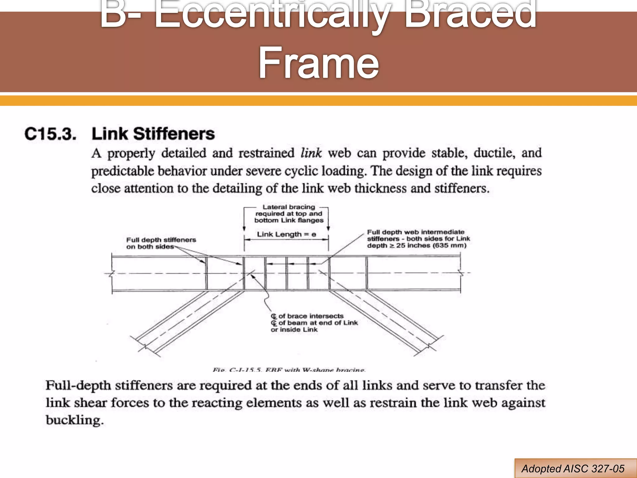
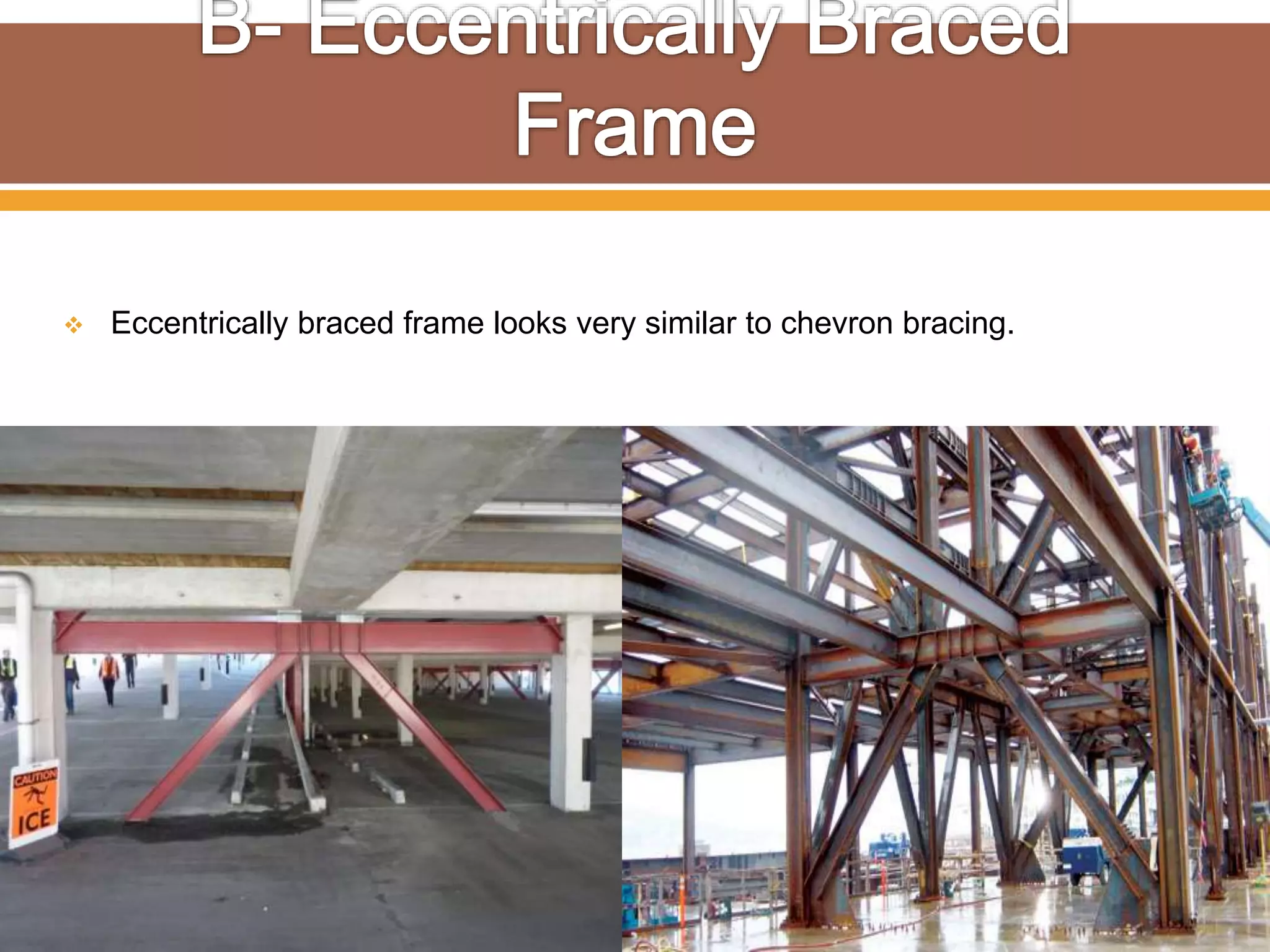
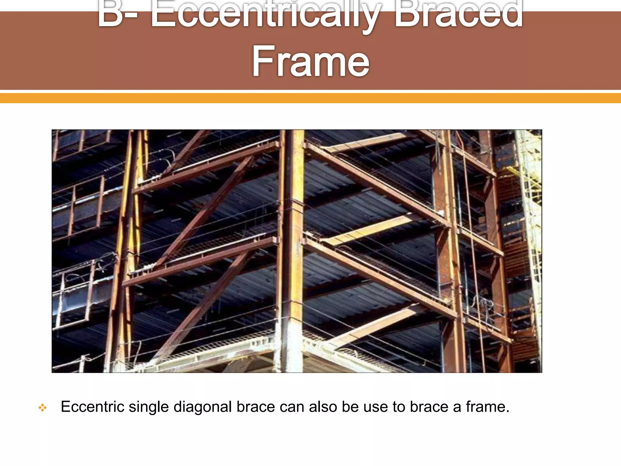
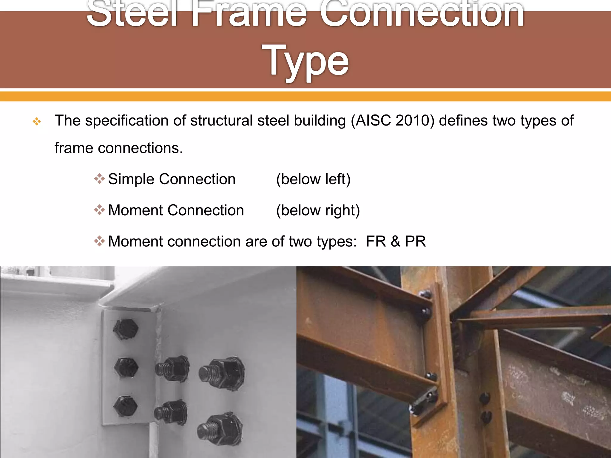
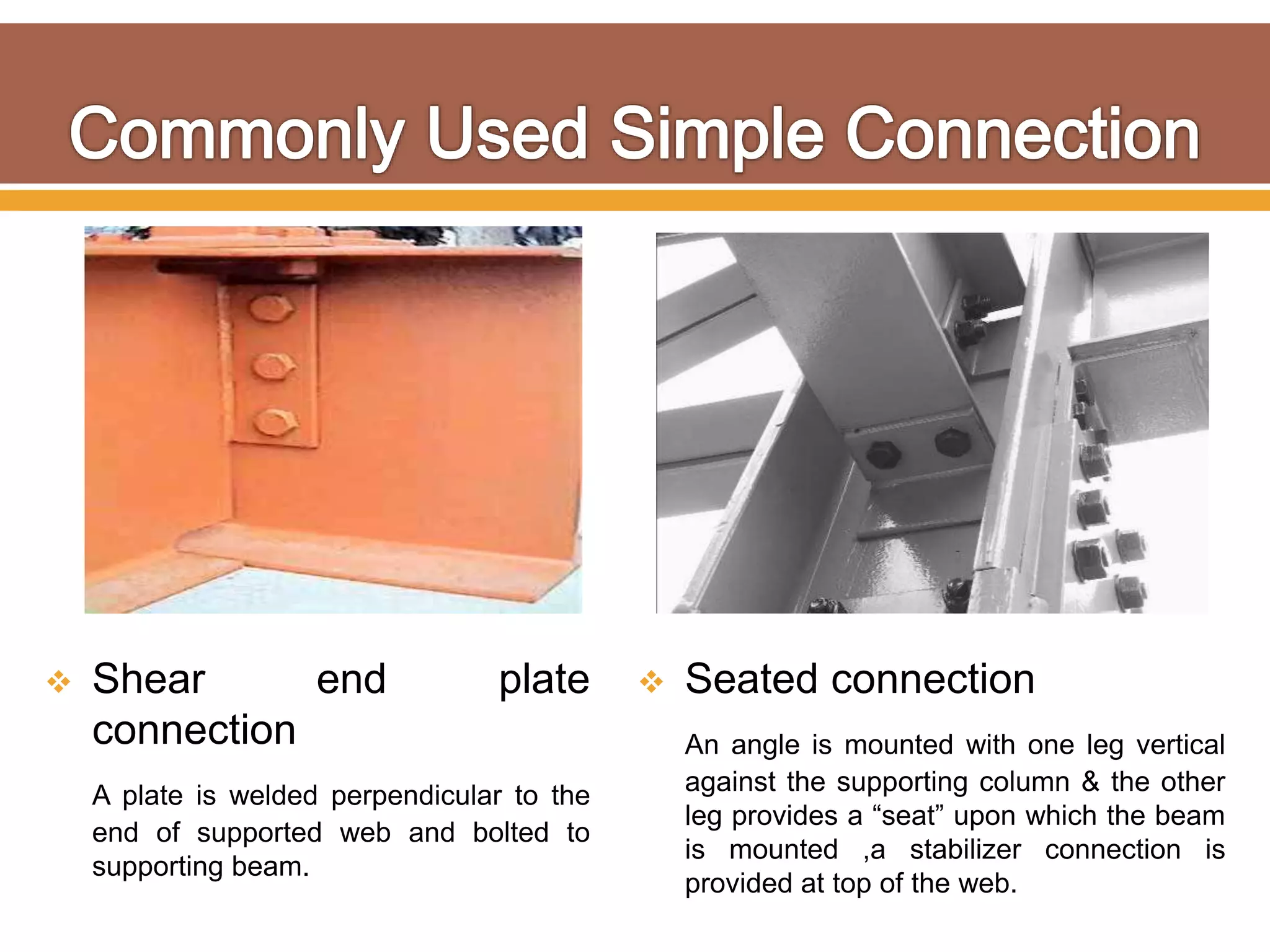
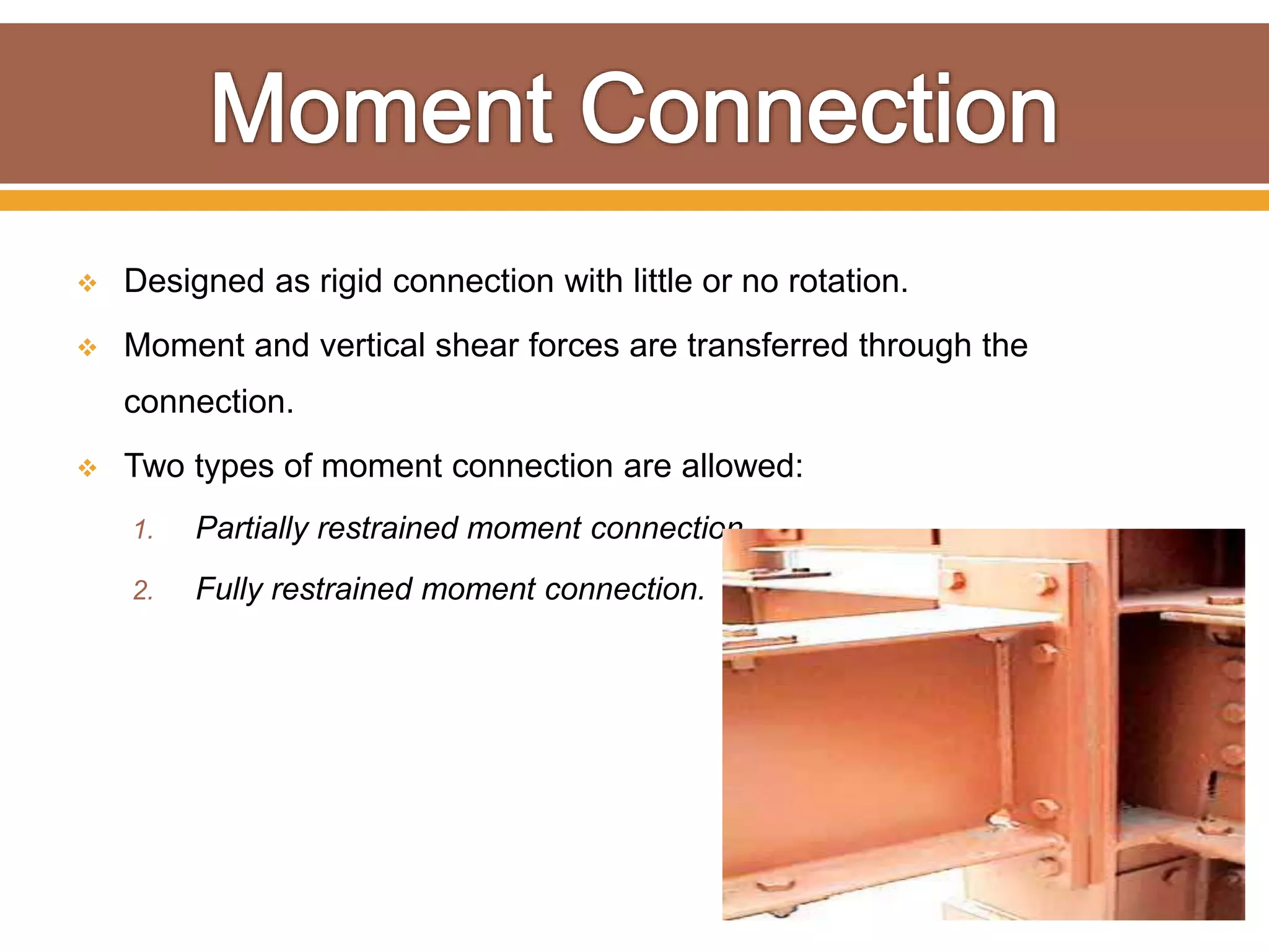
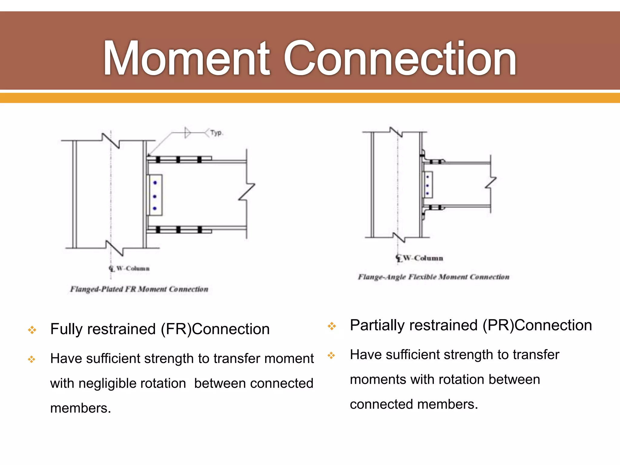
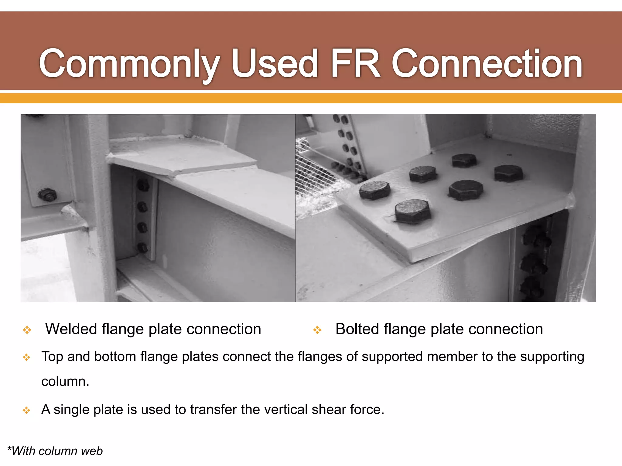
 
 Introduction
 Steps for Design
• Geometry Modeling
• Loading
• Design Parameters
• Analysis & Design
• Connections & Bracing
 Pipe Rack Design Flow Chart
 Benefits of Steel Structure
 Load Resisting Systems
 Frame Types
 Concentric / Eccentric Braced Frame
 Steel Frame Connection Types
Simple Connection
Moment Connection
EM Connection Capacity Design Flow Chart
 Reduced construction time & no seasonal effect.
 Light weight and reduced foundation cost.
 Durable , Long Lasting and Recyclable.
 Easier to modify and reinforce if required.
 Fabrication off-site possible (right).
 On site erection is a time saving process (left).
 Schedule advantage.
 Forces from Gravity ,wind and
seismic is imposed on all structures.
 Applied vertical forces are gravity
loads.
 Forces that act horizontally such as
wind, seismic require a lateral load
resisting system to be built in
structure.
 When lateral loads are applied to a
structure, horizontal diaphragm
transfer the load to the lateral load
resisting system.
Structural steel frame elevation
 The type of lateral load (Seismic, Wind, Friction, Thermal ) resisting system to
be used in a Structure Should be taken care in the Earlier Planning Stage.
Common lateral load resisting systems
Braced Frame Rigid Frame
 Rigid frame, utilize the moment connection and this type is preferred where
diagonal or x- bracing should avoid due to access requirement.
 Draw back of rigid frame is more cost than braced frame.
 Braced frame is the economical method of resisting wind load in multi storey
structural frame.
 Bracing creates triangular configuration in the structures.
 Some structures like below picture take the advantage of both rigid and
braced at the same time.
 Member or system that provides stiffness
and strength to limit the out of plan
movement of another member at the braced
point. (AISC Spec2010)
 Two types of bracing is defined in AISC
(1997) seismic provision in steel structural
building.
A. Concentric Bracing
B. Eccentric Bracing
 Concentrically braced frame are those in which the centerlines of members that
meet at a joint intersect at a same work point to form a vertical truss system that
resist lateral forces.
 Commonly used bracing system in steel structure is
X- bracing ( above left) Chevron (above right)
 Connection for X- bracing are
located at beam to column
joint.
 Bracing connection may
require large gusset plate at
the beam to column joint.
 The members used in chevron bracing
are designed for both compression and
tension
 Chevron bracings allows for doorways or
corridors through the bracing lines in a
structure.
“CHEVRON” “V” “DIAGONAL”
ELEVATION WITH SEVERAL BRACING CONFIGURATION
 Chevron bracing members use two types
of connections.
 The Floor level connection may use a
gusset plate as like in x-braced frame.
 The bracing members are connected to
the beam/girder at the top and converge to
a common point.
 When gusset plate is used, it in important
to consider their size when laying out any
mechanical equipment pass through
braced bays.
 Eccentric brace is commonly used in seismic regions and allow corridors and
walkway through bay frame.
 In an eccentrically braced frames, bracing connect to a separate work point on
beam/girder.
 The beam/girder segment or “link” between them absorbs energy from seismic
activity through plastic deformation.
Link
E/B with typical brace to beam connection
Eccentric Brace
Gusset Plate
Beam or Girder
Stiffeners
Adopted AISC 327-05
 Eccentrically braced frame looks very similar to chevron bracing.
 Eccentric single diagonal brace can also be use to brace a frame.
 The specification of structural steel building (AISC 2010) defines two types of
frame connections.
Simple Connection (below left)
Moment Connection (below right)
Moment connection are of two types: FR & PR
 Simple Connection: Connection that transmit negligible amount of bending
moment between connected members.
 Moment Connection: Connection that transmit bending moment between
connected members.
• Fully restrained moment connection FR : transfer moments with a negligible
amount of rotation between connected members.
• Partially restrained moment connection PR : transfer moments, but rotation
between connected members is not negligible.
 Simple connection (A) have rigidity but is assumed to rotate free.
 Connection (B & C) are examples of partially restrained moment
connections.
 Connection (D & E) are examples of fully restrained moment.
Adopted from Vol -II Connection .
 Connection is assumed to be rotation free.
 Vertical forces are primary forces transferred by the connection.
 For this Connection a separate resisting system is required to design.
 Single plate Connection
( Shear Tab)
A plate is welded to the supporting
member and bolted to the web of the
supported beam.
 Double Angle Connection
The in plane pair of legs are attached to
the web of the supported member and out
of plane pair of legs attached to the
supporting beam web or flange.
 Shear end plate
connection
A plate is welded perpendicular to the
end of supported web and bolted to
supporting beam.
 Seated connection
An angle is mounted with one leg vertical
against the supporting column & the other
leg provides a “seat” upon which the beam
is mounted ,a stabilizer connection is
provided at top of the web.
 Designed as rigid connection with little or no rotation.
 Moment and vertical shear forces are transferred through the
connection.
 Two types of moment connection are allowed:
1. Partially restrained moment connection.
2. Fully restrained moment connection.
 Fully restrained (FR)Connection
 Have sufficient strength to transfer moment
with negligible rotation between connected
members.
 Partially restrained (PR)Connection
 Have sufficient strength to transfer
moments with rotation between
connected members.
 Welded flange plate connection  Bolted flange plate connection
*With column web
 Top and bottom flange plates connect the flanges of supported member to the supporting
column.
 A single plate is used to transfer the vertical shear force.
 Bolted extended end plate
connection
 A plate is welded to the end of
supported beam and bolted to the
supporting column flange.
 Welded flange connection
 Complete joint penetration groove
welds directly top and bottom
flanges of the supported member
to supporting column.
 A shear connection at web is used
to transfer the vertical shear force.
*With column
 PR moment connection
 A double angle simple connection
transfers vertical shear forces while top
and bottom flange plates resist moment
forces produced by wind.
 Top and bottom angle with shear
end plate connection
 Angles are bolted or welded to the top
and bottom flanges of the supported
member and to the supporting column.
 A shear end plate on the web is used to
transfer vertical shear forces.
End Moment
Connection
(1) MEMBER
Mm = 0.6Fy x Sx (kN-m)
Vm = 0.4Fy x Awn (kN)
Tm = 0.6Fy x 2Af (kN)
Af = bfb x tfb (mm2)
Awn = ( d1 - 2tfb ) x twb
(mm2)
(2) HIGH STRENGTH BOLT
Mb = n1 x Qt x ( d1 - tfb ) (kN-m)
Vb = n2 x Qs (kN)
Tb = 2 x n1 x Qt (kN)
n1= Number of tension bolts
n2= Total Number of bolts
(4) END PLATE
Mp = Ff x ( d1 - tfb ) (kN-m)
Tp = 2 x Ff (kN)
Ff = 4 x Me / ( αm x Pe ) (kN)
Me = bp x 0.75Fy x tp2 / 6 (kN-m)
αm = Ca x Cb x (Af / Aw)1/3 x (Pe /
db)1/4
Pe = Pf - (db / 4) - 0.707S1 (mm)
Ca = 1.13
Cb = ( bfb / bp )1/2
db = (mm)
Aw = twb x (d1 - 2tfb) (mm2)
(5) STIFFENER DESIGN
(5-1) COLUMN FLANGE BENDING
STRENGTH
Fcap = 4 x Me /( αm x Pe )
Me = bs x 0.75Fy x tfc2 / 6 (kN)
bs= 2.5 x ( Pf + tfb + Pf ) (kN-m)
Pe = g / 2 - db / 4 - k1 (mm)
αm = Ca x Cb x ( Af / Aw )1/3 x ( Pe / db )1/4
(mm)
Af / Aw = 1.0
min Mst = Ff x ( d1 - tfb ) (kN-m)
Ff = Fcap + Fst (kN)
min Tst = 2Ff (kN)
(5-2) TENSION CAPACITY OF STIFFENER
PLATE
Fst = 0.6Fy x Ast (kN)
Ast = ts x ( bfc - twc - 2 x 5 - 2 x 25 ) (mm2)
(5-3) SHEAR CAPACITY OF STIFFENER
PLATE
Fst = 0.4Fy x Ast (kN)
(5-4) STIFFENER WELD CAPACITY OF
COLUMN FLANGE
Fst = fw x Ast (kN)
Ast = 0.707 x lw x Sflg (mm
(5-5) STIFFENER WELD CAPACITY OF
COLUMN WEB
Fst = fw x Ast (kN)
Ast = 0.707 x lw x Sweb (mm2)
lw = 4 x (dc/2 - tfc - 25 - Sweb) : HALF
lw = 4 x (dc - 2tfc - 2x25 - 2xSweb) : FULL
(3) WELD
Mw = Ff x ( d1 - tfb ) (kN-m)
Ff = Fw x Awf (kN)
Vw = Fw x Aww(kN)
Tw = Fw x 2Awf
Awf = 0.707 x S1 x (2bfb+2tfb-twb )
(mm2) Aww = 0.707 S2 x ( d1 / 2 - tfb ) x
2 (mm2)
SAFE LOAD OF CONNECTION
Ma =min.(Mm,Mw,Mb,Mp,Mst) (kN-m)
Ta = min.(Tm,Tw,Tb,Tp,Tst) (kN)
Va = min. (Vm,Vw,Vb) (kN)
 AISC VOLUME-II CONNECTION
 CONNECTION TEACHING TOOLKIT (AISC)
 AISC 327-05 SEISMIC DESIGN MANUAL
 AISC 2010 SPECIFICATION FOR STRUCTURAL
STEEL BLDGS
Connection and Bracing

Connection and Bracing

  • 1.
  • 2.
     Introduction  Stepsfor Design • Geometry Modeling • Loading • Design Parameters • Analysis & Design • Connections & Bracing  Pipe Rack Design Flow Chart
  • 3.
     Benefits ofSteel Structure  Load Resisting Systems  Frame Types  Concentric / Eccentric Braced Frame  Steel Frame Connection Types Simple Connection Moment Connection EM Connection Capacity Design Flow Chart
  • 4.
     Reduced constructiontime & no seasonal effect.  Light weight and reduced foundation cost.  Durable , Long Lasting and Recyclable.  Easier to modify and reinforce if required.
  • 5.
     Fabrication off-sitepossible (right).  On site erection is a time saving process (left).  Schedule advantage.
  • 6.
     Forces fromGravity ,wind and seismic is imposed on all structures.  Applied vertical forces are gravity loads.  Forces that act horizontally such as wind, seismic require a lateral load resisting system to be built in structure.  When lateral loads are applied to a structure, horizontal diaphragm transfer the load to the lateral load resisting system. Structural steel frame elevation
  • 7.
     The typeof lateral load (Seismic, Wind, Friction, Thermal ) resisting system to be used in a Structure Should be taken care in the Earlier Planning Stage. Common lateral load resisting systems Braced Frame Rigid Frame
  • 8.
     Rigid frame,utilize the moment connection and this type is preferred where diagonal or x- bracing should avoid due to access requirement.  Draw back of rigid frame is more cost than braced frame.
  • 9.
     Braced frameis the economical method of resisting wind load in multi storey structural frame.  Bracing creates triangular configuration in the structures.  Some structures like below picture take the advantage of both rigid and braced at the same time.
  • 10.
     Member orsystem that provides stiffness and strength to limit the out of plan movement of another member at the braced point. (AISC Spec2010)  Two types of bracing is defined in AISC (1997) seismic provision in steel structural building. A. Concentric Bracing B. Eccentric Bracing
  • 11.
     Concentrically bracedframe are those in which the centerlines of members that meet at a joint intersect at a same work point to form a vertical truss system that resist lateral forces.
  • 12.
     Commonly usedbracing system in steel structure is X- bracing ( above left) Chevron (above right)
  • 13.
     Connection forX- bracing are located at beam to column joint.  Bracing connection may require large gusset plate at the beam to column joint.
  • 14.
     The membersused in chevron bracing are designed for both compression and tension  Chevron bracings allows for doorways or corridors through the bracing lines in a structure. “CHEVRON” “V” “DIAGONAL” ELEVATION WITH SEVERAL BRACING CONFIGURATION
  • 15.
     Chevron bracingmembers use two types of connections.  The Floor level connection may use a gusset plate as like in x-braced frame.  The bracing members are connected to the beam/girder at the top and converge to a common point.  When gusset plate is used, it in important to consider their size when laying out any mechanical equipment pass through braced bays.
  • 16.
     Eccentric braceis commonly used in seismic regions and allow corridors and walkway through bay frame.  In an eccentrically braced frames, bracing connect to a separate work point on beam/girder.  The beam/girder segment or “link” between them absorbs energy from seismic activity through plastic deformation. Link E/B with typical brace to beam connection Eccentric Brace Gusset Plate Beam or Girder Stiffeners
  • 17.
  • 18.
     Eccentrically bracedframe looks very similar to chevron bracing.
  • 19.
     Eccentric singlediagonal brace can also be use to brace a frame.
  • 20.
     The specificationof structural steel building (AISC 2010) defines two types of frame connections. Simple Connection (below left) Moment Connection (below right) Moment connection are of two types: FR & PR
  • 21.
     Simple Connection:Connection that transmit negligible amount of bending moment between connected members.  Moment Connection: Connection that transmit bending moment between connected members. • Fully restrained moment connection FR : transfer moments with a negligible amount of rotation between connected members. • Partially restrained moment connection PR : transfer moments, but rotation between connected members is not negligible.
  • 22.
     Simple connection(A) have rigidity but is assumed to rotate free.  Connection (B & C) are examples of partially restrained moment connections.  Connection (D & E) are examples of fully restrained moment. Adopted from Vol -II Connection .
  • 23.
     Connection isassumed to be rotation free.  Vertical forces are primary forces transferred by the connection.  For this Connection a separate resisting system is required to design.
  • 24.
     Single plateConnection ( Shear Tab) A plate is welded to the supporting member and bolted to the web of the supported beam.  Double Angle Connection The in plane pair of legs are attached to the web of the supported member and out of plane pair of legs attached to the supporting beam web or flange.
  • 25.
     Shear endplate connection A plate is welded perpendicular to the end of supported web and bolted to supporting beam.  Seated connection An angle is mounted with one leg vertical against the supporting column & the other leg provides a “seat” upon which the beam is mounted ,a stabilizer connection is provided at top of the web.
  • 26.
     Designed asrigid connection with little or no rotation.  Moment and vertical shear forces are transferred through the connection.  Two types of moment connection are allowed: 1. Partially restrained moment connection. 2. Fully restrained moment connection.
  • 27.
     Fully restrained(FR)Connection  Have sufficient strength to transfer moment with negligible rotation between connected members.  Partially restrained (PR)Connection  Have sufficient strength to transfer moments with rotation between connected members.
  • 28.
     Welded flangeplate connection  Bolted flange plate connection *With column web  Top and bottom flange plates connect the flanges of supported member to the supporting column.  A single plate is used to transfer the vertical shear force.
  • 29.
     Bolted extendedend plate connection  A plate is welded to the end of supported beam and bolted to the supporting column flange.  Welded flange connection  Complete joint penetration groove welds directly top and bottom flanges of the supported member to supporting column.  A shear connection at web is used to transfer the vertical shear force. *With column
  • 30.
     PR momentconnection  A double angle simple connection transfers vertical shear forces while top and bottom flange plates resist moment forces produced by wind.  Top and bottom angle with shear end plate connection  Angles are bolted or welded to the top and bottom flanges of the supported member and to the supporting column.  A shear end plate on the web is used to transfer vertical shear forces.
  • 31.
    End Moment Connection (1) MEMBER Mm= 0.6Fy x Sx (kN-m) Vm = 0.4Fy x Awn (kN) Tm = 0.6Fy x 2Af (kN) Af = bfb x tfb (mm2) Awn = ( d1 - 2tfb ) x twb (mm2) (2) HIGH STRENGTH BOLT Mb = n1 x Qt x ( d1 - tfb ) (kN-m) Vb = n2 x Qs (kN) Tb = 2 x n1 x Qt (kN) n1= Number of tension bolts n2= Total Number of bolts (4) END PLATE Mp = Ff x ( d1 - tfb ) (kN-m) Tp = 2 x Ff (kN) Ff = 4 x Me / ( αm x Pe ) (kN) Me = bp x 0.75Fy x tp2 / 6 (kN-m) αm = Ca x Cb x (Af / Aw)1/3 x (Pe / db)1/4 Pe = Pf - (db / 4) - 0.707S1 (mm) Ca = 1.13 Cb = ( bfb / bp )1/2 db = (mm) Aw = twb x (d1 - 2tfb) (mm2) (5) STIFFENER DESIGN (5-1) COLUMN FLANGE BENDING STRENGTH Fcap = 4 x Me /( αm x Pe ) Me = bs x 0.75Fy x tfc2 / 6 (kN) bs= 2.5 x ( Pf + tfb + Pf ) (kN-m) Pe = g / 2 - db / 4 - k1 (mm) αm = Ca x Cb x ( Af / Aw )1/3 x ( Pe / db )1/4 (mm) Af / Aw = 1.0 min Mst = Ff x ( d1 - tfb ) (kN-m) Ff = Fcap + Fst (kN) min Tst = 2Ff (kN) (5-2) TENSION CAPACITY OF STIFFENER PLATE Fst = 0.6Fy x Ast (kN) Ast = ts x ( bfc - twc - 2 x 5 - 2 x 25 ) (mm2) (5-3) SHEAR CAPACITY OF STIFFENER PLATE Fst = 0.4Fy x Ast (kN) (5-4) STIFFENER WELD CAPACITY OF COLUMN FLANGE Fst = fw x Ast (kN) Ast = 0.707 x lw x Sflg (mm (5-5) STIFFENER WELD CAPACITY OF COLUMN WEB Fst = fw x Ast (kN) Ast = 0.707 x lw x Sweb (mm2) lw = 4 x (dc/2 - tfc - 25 - Sweb) : HALF lw = 4 x (dc - 2tfc - 2x25 - 2xSweb) : FULL (3) WELD Mw = Ff x ( d1 - tfb ) (kN-m) Ff = Fw x Awf (kN) Vw = Fw x Aww(kN) Tw = Fw x 2Awf Awf = 0.707 x S1 x (2bfb+2tfb-twb ) (mm2) Aww = 0.707 S2 x ( d1 / 2 - tfb ) x 2 (mm2) SAFE LOAD OF CONNECTION Ma =min.(Mm,Mw,Mb,Mp,Mst) (kN-m) Ta = min.(Tm,Tw,Tb,Tp,Tst) (kN) Va = min. (Vm,Vw,Vb) (kN)
  • 32.
     AISC VOLUME-IICONNECTION  CONNECTION TEACHING TOOLKIT (AISC)  AISC 327-05 SEISMIC DESIGN MANUAL  AISC 2010 SPECIFICATION FOR STRUCTURAL STEEL BLDGS