This presentation summarizes the key aspects of one-way slab design:
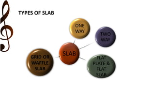
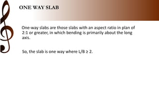
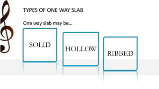
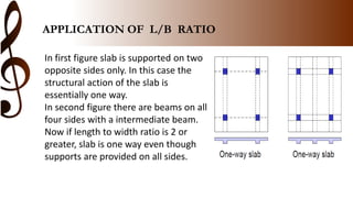
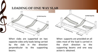
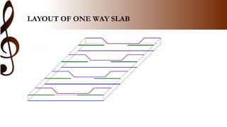
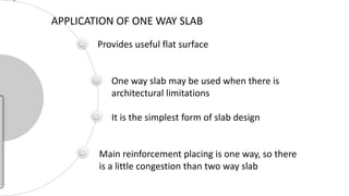
1) One-way slabs have an aspect ratio of 2:1 or greater, where bending occurs primarily along the long axis. They can be solid, hollow, or ribbed.
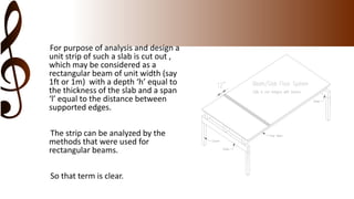
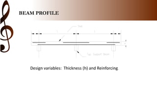
2) Design and analysis treats a unit strip of the slab as a rectangular beam of unit width and the slab thickness as the depth.
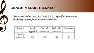
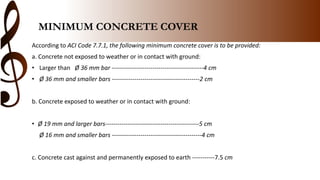
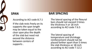
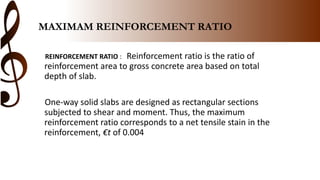
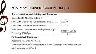
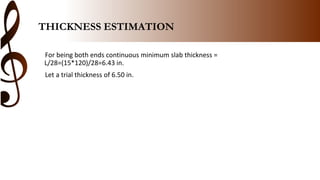
3) The ACI code specifies minimum slab thickness, concrete cover, span length, bar spacing, reinforcement ratios, and other design requirements.
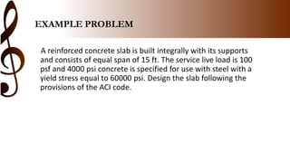
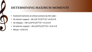
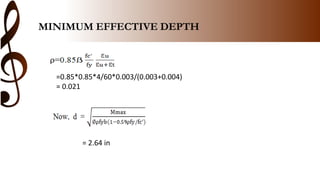
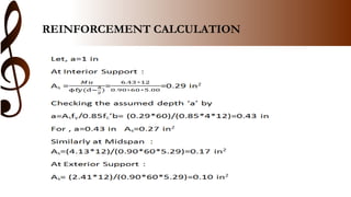
4) An example problem demonstrates the design process, calculating loads, moments, minimum reinforcement, and checking the proposed slab thickness.
5) One-


![presentation on detailing of slab by group TULIP [Autosaved].pptx](https://cdn.slidesharecdn.com/ss_thumbnails/presentationondetailingofslabbygrouptulipautosaved-250830134807-ace00faf-thumbnail.jpg?width=640&height=640&fit=bounds)


