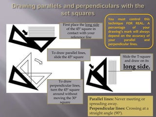
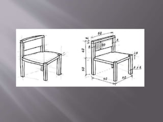
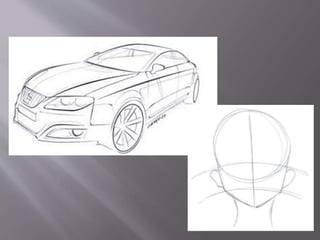
Graphic representation of
technological projects
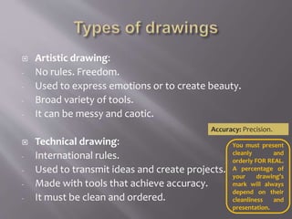
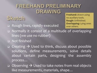
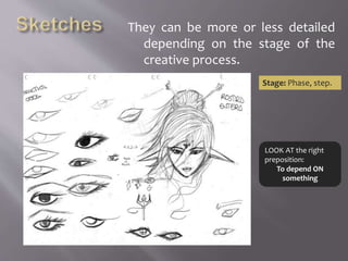
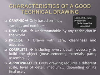
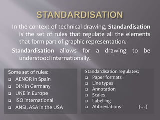
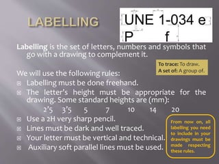
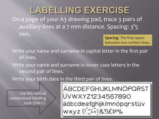
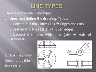
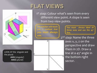
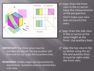
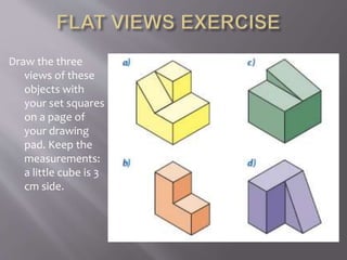
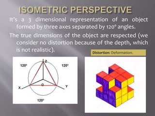
 Expression of ideas, feelings and emotions
through drawing.
 It’s used to express ideas… from very simple to
really complex.
 Drawing is a universal language.
 Written characters are drawings.
 Artistic drawing:
- No rules. Freedom.
- Used to express emotions or to create beauty.
- Broad variety of tools.
- It can be messy and caotic.
 Technical drawing:
- International rules.
- Used to transmit ideas and create projects.
- Made with tools that achieve accuracy.
- It must be clean and ordered.
Accuracy: Precision.
You must present
cleanly and
orderly FOR REAL.
A percentage of
your drawing’s
mark will always
depend on their
cleanliness and
presentation.
Do the following drawings transmit ideas or
feelings?
Do you think they are artistic or technical drawings?
Are they graphic representations of things?
 Looking for solutions to a problem.
 Organizing ideas.
 Designing objects in detail (parts, dimensions,
assembly…)
 Showing ideas to other people and debating
about them.
 Giving instructions to assemble a product.
 Adding aesthetic value to a design.
To assemble: To mount, put together.
Aesthetic: Tasteful, beautiful.
LOOK AT the spelling of this word:
D-E-S-I-G-N
DIN A4
210 x 297 mm
21 x 29,7 cm
DIN A3
297 x 420 mm
29,7 x 42 cm
DIN A2
Can you guess
its size?
DIN A1
Can you guess
its size?
DIN A0
Can you guess
its size?
 They are used directly on paper to draw.
 PENCILS Hardness.
H = Hard (the higher its number, the harder)
HB= Medium
B = Bland (the higher its number, the softer)
 TECHNICAL PENS  Thickness.
 FELT-TIP PENS  Colour.
Using the right pencil for every
situation will be crucial for your
marks.
 They help us to draw accurately.
45º SQUARE 30º (or 30-60º) SQUARE
PROTRACTOR
RULER
COMPASS
LOOK AT the spelling of this word:
P-R-O-T-R-A-C-T-O-R
First place the long side
of the 45º square in
contact with your
reference line
To draw parallel lines,
slide the 45º square
To draw
perpendicular lines,
turn the 45º square
around without
moving the 30º
square
Slide the T-square
and draw on its
long side.
You must control this
technique FOR REAL. A
percentage of your
drawing’s mark will always
depend on the accuracy of
your parallel and
perpendicular lines.
Parallel lines: Never meeting or
spreading away.
Perpendicular lines: Crossing at a
straight angle (90º).
 Rough lines, rapidly executed
 Normally it consist of a multitude of overlapping
lines (we use no rubber)
 Not finished
 Creating  Used to think, discuss about possible
solutions, define measurements, solve details
about certain parts, designing the assembly
process…
 Observing  Used to take notes from real objects
like measurements, materials, shape…
Freehand: drawn using
no auxiliary tools.
Rough: Unfinished.
Overlapping: Lying ones
over others.
They can be more or less detailed
depending on the stage of the
creative process.
LOOK AT the right
preposition:
To depend ON
something
Stage: Phase, step.
 GRAPHIC  Only based on lines,
symbols and numbers.
 UNIVERSAL  Understandable by any technician in
the World.
 PRECISE  Drawn with care, cleanliness and
accuracy.
 COMPLETE  Including every detail necessary to
build the object (measurements, materials, parts,
assembly…)
 APPROPRIATE  Every drawing requires a different
scale, level of detail, medium… depending on its
final user.
LOOK AT the right
preposition:
To be based ON
something
In the context of technical drawing, Standardisation
is the set of rules that regulate all the elements
that form part of graphic representation.
Standardisation allows for a drawing to be
understood internationally.
Some set of rules:
 AENOR in Spain
 DIN in Germany
 UNE in Europe
 ISO international
 ANSI, ASA in the USA
Standardisation regulates:
 Paper formats
 Line types
 Annotation
 Scales
 Labelling
 Abbreviations (…)
Labelling is the set of letters, numbers and symbols that
go with a drawing to complement it.
We will use the following rules:
 Labelling must be done freehand.
 The letter’s height must be appropriate for the
drawing. Some standard heights are (mm):
2’5 3’5 5 7 10 14 20
 Use a 2H very sharp pencil.
 Lines must be dark and well traced.
 Your letter must be vertical and technical.
 Auxiliary soft parallel lines must be used.
To trace: To draw.
A set of: A group of.
From now on, all
labelling you need
to include in your
drawings must be
made respecting
these rules.
On a page of your A3 drawing pad, trace 3 pairs of
auxiliary lines at a 7 mm distance. Spacing: 3’5
mm.
Write your name and surname in capital letter in the first pair
of lines.
Write your name and surname in lower case letters in the
second pair of lines.
Write your birth date in the third pair of lines.
Spacing: The free space
between two written lines.
Use this vertical
standardized labelling
style (DIN17).
There are two main line types:
 Lines that define the drawing. Types:
a) Continuous thick lines (2B)  Edges and cuts.
b)Dashed thin lines (2H)  Hidden edges.
c) Dashed thin lines with dots (2H)  Axis of
symmetry.
 Auxiliary lines.
Continuous thin
lines (2H).
On the page where you
practice your labelling,
draw a sketch of the three
flat views of this object.
Try to keep the proportions
although you don’t know
its measurements.
Now, draw them with your
set squares using the right
types of lines.
Annotation consists of expressing the real measurements
of an object on a plan.
Annotation makes the plan easier to read and interpret. It
allows us to see the measurements of an object at a
glance.
Annotations must be clear, clean
and precise:
a) Drawn more lightly than the
lines of the drawing.
b) Parallel lines must be REALLY
PARALLEL.
c) The size of the numbers must
be not too big nor too small.
Plan: Technical drawing
that represents a view of
an object or building.
LOOK AT the right
spelling:
A-N-N-OTATION
a) Extension lines Thin, continuous (2H)  They
indicate the portion of the drawing we are
measuring.
b) Annotation lines Thin, continuous (2H) 
Parallel to the edge (at the right distance) and
measuring the same.
c) Arrow heads  Thin (2H)  On both annotation
line endings, they indicate the dimension labelled.
d) Annotation  Thin and correctly labelled (vertical
standard writing) (2H)  Number that indicates
the real measurement of the portion annotated.
Arrow head
Annotation line
Annotation
Extension
line
Different arrow head styles
Pay attention to all these rules and learn by
practising. A drawing needs to abide by these
rules to be good.
1- Annotations must never be written on the edge but on
top of the annotation line.
2- Annotation lines must never cross, touch or overlap an
edge of the object. Extension lines must be used. Leave
a reasonable distance (0,8 cm minimum) between
edge and annotation line.
3- Extension lines extend 2-3
mm from the annotation
line. They must touch the
edge they are marking.
4- Annotations must be
placed above the line and
centered on it. On vertical
edges, think about a
clockwise turn.
5- The units must never be
indicated on the annotation.
We just write the
measurement (normally in
mm) and express the units
on the plan.
DIMENSIONS IN mm
6- You must indicate all necessary measurements for
building the object.
7- You must not repeat any measurement
unnecessarily.
8- Annotation lines must never cross nor cross an edge. It’s
fine to cross two extension lines or an extension line and
an edge.
To avoid crossing, we must plan the position of the
annotation lines carefully.
9- We must arrange annotations in an orderly way.
Standard
annotation
systems
ANNOTATION OF ARCS AND
CIRCUMFERENCES
 We use the SYMBOLS R (radius) y Ф (diameter).
 We draw with DASHED LINES WITH DOTS two
diameters (vertical and horizontal) and the center of
the arc/circumference. The annotation line must be
DIAGONAL.
 If the annotation doesn’t fit inside, we can extend the
annotation line and write it ouside.
ANNOTATION OF
PERSPECTIVE DRAWINGS
Extension and annotation
lines must always be
parallel to the edges of
the object.
Go back to the front
view of this object
you drew in your
pad.
Measure it and write
annotations,
following all the
rules.
 FLAT VIEWS
The flat views (o dihedral views) of an object are 2 dimension
images perceived by an observer placed on a plane parallel
to the object’s main sides.
We draw them following the European system.
 PERSPECTIVE Plane: A flat or level surface.
Drawing a perspective is
trying to show a 3
dimensional reality onto a 2
dimensional medium.
The perspectives that we’ll
use are cavalier and
isometric perspectives.
Dihedral: having or containing
two plane faces.
Remember:
NOUN - ADJECTIVE
Height – High
Depth - Deep
Width - Wide
Front, side and top views are
the result of projecting an
object onto an imaginary
trihedron.
That trihedron, with the 3
projections, later unfolds
and shows the views in
correlative positions.
Trihedron: Volume formed by
three planes that intersect at
three 90º angles.
2nd step: Name the three
axes x, y, z on the
perspective and draw
them in 2D. Draw a
line at a 45º angle in
the bottom right
sector.
z
y
x
z
y
x
x
1st step: Colour what’s seen from every
different view point. A slope is seen
from two view points.
LOOK AT the singular and
the plural:
AXIS (singular)
AXES (plural)
You must always label all
three axes and use the 45º
line.
The teacher will teach
you a method that
you must always
use.
3rd step: Draw the front
view in the xy sector.
Keep the measurements
of the perspective.
Don’t make your view
lean on (touch) the
axes.
4o step: Draw the side view
in the xz sector at the
same height as the
front. Use auxiliary lines.
5th step: the top view in the
xy sector using the 45º
line and auxiliary lines.
It must be right under
the front view.
z
y
x
IMPORTANT: The three views must be
correlatively placed. We use auxiliary soft
lines and the 45º angle line to achieve that .
REMEMBER: Hidden edges are represented by
dashed lines. Symmetry axes by dashed lines
with dots.
z
y
x
x
Front
view
Front view Side view
Top view
Draw the three
views of these
objects with
your set squares
on a page of
your drawing
pad. Keep the
measurements:
a little cube is 3
cm side.
It’s a 3 dimensional representation of an object
formed by three axes separated by 120º angles.
The true dimensions of the object are respected (we
consider no distortion because of the depth, which
is not realistic). Distortion: Deformation.
We can easily trace the axes using our set squares:
You must practise this
technique until you are able
to do it without help.
On one of your pad’s pages, draw the three axes at
120º and then draw this cube of 6 cm side.
First, draw everything softly
with your 2H pencil.
Then, outline all visible edges
with your 2B pencil (don’t
erase anything).
On one of your
pad’s pages,
draw these
objects.
Remember that they
are based on a
small 3cm side
cube.
First, draw everything
softly with your 2H
pencil.
Then, outline all visible
edges with your 2B
pencil (don’t erase
anything).
Your teacher will teach you the process you must
always follow when you want to draw an isometric
perspective. Learn and use this method, ALWAYS.
On a pad’s page, draw the three axes at 120º 7 times,
using your set squares.
Then draw a sketch of all these pieces of furniture.
First, draw everything softly with
your 2H pencil.
Then, outline all visible edges with
your 2B pencil (don’t erase anything).
Remember your
teacher’s method.
Draw this chair on a page of your drawing pad, using
your set squares. Imagine the dimensions are in
mm.
Don’t annotate!
First, draw everything softly with
your 2H pencil.
Then, outline all visible edges
with your 2B pencil (don’t erase
anything).
Remember your
teacher’s method.
Draw these object on a pad’s page in the isometric
perspective, respecting the dimensions and using
your set squares. Don’t annotate.
Remember your
teacher’s method.
Draw these object on a pad’s page in the isometric
perspective, respecting the dimensions and using
your set squares. Don’t annotate.
Then, draw the three flat views of the object at the
same scale.
The scale is the relation between the measurements in
a drawing and the real measurements of a physical
object.
S=1  Natural scale (1:1)
Objects are represented as they are, so there’s no confusion.
e>1  Enlargement scale
It’s used to draw small objects bigger than they are, so we can
represent details (2:1, 10:1…).
To guess the real measurements, we’ll divide the size in the drawing by the scale.
e<1  Reduction scale
It’s used to represent big objects smaller than they are, so
they can fit the paper (1:75, 1:100, 1:1000, 1:10.000…).
To guess the real measurements, we’ll multiply the size in the drawing by the scale.
Measurements in the plane
Scale =
Measurements in reality
What scale type would you use to represent…?
- A truck.
- A mobile phone.
- The roads net of a country.
- A pin.
- A screw.
- A house.
- A computer’s motherboard.
- The human body’s muscles.
- A dragonfly.
- A cell.
An area is represented on a 1:5.000 map. How many
kilometers will separate two towns in the real
territory, if they are separated by 20 cm in the map?
We solve this using a rule of three:
DRAWING REALITY
1 cm in the map____________ 5.000 real cm
20 cm in the map___________ x real cm
x = 20 · 5.000 / 1= 100.000 cm = 1 km
Understand and
use this method
for all these
problems.
PAY
ATTENTION TO
UNITS!!!!
What scale shall we use to represent a football pitch
measuring 75 x 100 m so that it fits a Din-A3 paper
(42 x 29,7 cm)?
We solve this by a rule of three, thinking of the long
side of the paper and leaving a bit of free space:
DRAWING REALITY
1 cm in the plane____________ x real cm
38 cm in the plane___________ 10.000 real cm
x = 1 · 10.000 / 38= 263 cm
Escala: 1:300
When we want to choose the scale to represent a
certain object on a plane, we must take into
account that there is a series of standardized
scales:
Reduction scales
Enlargement
scales
Manufacturing and
installations
Arquitecture, building and
civil works
Topography and
Geography
Urbanism

01 graphic representation

  • 1.
  • 3.
     Expression ofideas, feelings and emotions through drawing.  It’s used to express ideas… from very simple to really complex.  Drawing is a universal language.  Written characters are drawings.
  • 4.
     Artistic drawing: -No rules. Freedom. - Used to express emotions or to create beauty. - Broad variety of tools. - It can be messy and caotic.  Technical drawing: - International rules. - Used to transmit ideas and create projects. - Made with tools that achieve accuracy. - It must be clean and ordered. Accuracy: Precision. You must present cleanly and orderly FOR REAL. A percentage of your drawing’s mark will always depend on their cleanliness and presentation.
  • 5.
    Do the followingdrawings transmit ideas or feelings? Do you think they are artistic or technical drawings? Are they graphic representations of things?
  • 10.
     Looking forsolutions to a problem.  Organizing ideas.  Designing objects in detail (parts, dimensions, assembly…)  Showing ideas to other people and debating about them.  Giving instructions to assemble a product.  Adding aesthetic value to a design. To assemble: To mount, put together. Aesthetic: Tasteful, beautiful. LOOK AT the spelling of this word: D-E-S-I-G-N
  • 12.
    DIN A4 210 x297 mm 21 x 29,7 cm DIN A3 297 x 420 mm 29,7 x 42 cm DIN A2 Can you guess its size? DIN A1 Can you guess its size? DIN A0 Can you guess its size?
  • 13.
     They areused directly on paper to draw.  PENCILS Hardness. H = Hard (the higher its number, the harder) HB= Medium B = Bland (the higher its number, the softer)  TECHNICAL PENS  Thickness.  FELT-TIP PENS  Colour. Using the right pencil for every situation will be crucial for your marks.
  • 14.
     They helpus to draw accurately. 45º SQUARE 30º (or 30-60º) SQUARE
  • 15.
    PROTRACTOR RULER COMPASS LOOK AT thespelling of this word: P-R-O-T-R-A-C-T-O-R
  • 16.
    First place thelong side of the 45º square in contact with your reference line To draw parallel lines, slide the 45º square To draw perpendicular lines, turn the 45º square around without moving the 30º square Slide the T-square and draw on its long side. You must control this technique FOR REAL. A percentage of your drawing’s mark will always depend on the accuracy of your parallel and perpendicular lines. Parallel lines: Never meeting or spreading away. Perpendicular lines: Crossing at a straight angle (90º).
  • 18.
     Rough lines,rapidly executed  Normally it consist of a multitude of overlapping lines (we use no rubber)  Not finished  Creating  Used to think, discuss about possible solutions, define measurements, solve details about certain parts, designing the assembly process…  Observing  Used to take notes from real objects like measurements, materials, shape… Freehand: drawn using no auxiliary tools. Rough: Unfinished. Overlapping: Lying ones over others.
  • 19.
    They can bemore or less detailed depending on the stage of the creative process. LOOK AT the right preposition: To depend ON something Stage: Phase, step.
  • 23.
     GRAPHIC Only based on lines, symbols and numbers.  UNIVERSAL  Understandable by any technician in the World.  PRECISE  Drawn with care, cleanliness and accuracy.  COMPLETE  Including every detail necessary to build the object (measurements, materials, parts, assembly…)  APPROPRIATE  Every drawing requires a different scale, level of detail, medium… depending on its final user. LOOK AT the right preposition: To be based ON something
  • 25.
    In the contextof technical drawing, Standardisation is the set of rules that regulate all the elements that form part of graphic representation. Standardisation allows for a drawing to be understood internationally. Some set of rules:  AENOR in Spain  DIN in Germany  UNE in Europe  ISO international  ANSI, ASA in the USA Standardisation regulates:  Paper formats  Line types  Annotation  Scales  Labelling  Abbreviations (…)
  • 26.
    Labelling is theset of letters, numbers and symbols that go with a drawing to complement it. We will use the following rules:  Labelling must be done freehand.  The letter’s height must be appropriate for the drawing. Some standard heights are (mm): 2’5 3’5 5 7 10 14 20  Use a 2H very sharp pencil.  Lines must be dark and well traced.  Your letter must be vertical and technical.  Auxiliary soft parallel lines must be used. To trace: To draw. A set of: A group of. From now on, all labelling you need to include in your drawings must be made respecting these rules.
  • 27.
    On a pageof your A3 drawing pad, trace 3 pairs of auxiliary lines at a 7 mm distance. Spacing: 3’5 mm. Write your name and surname in capital letter in the first pair of lines. Write your name and surname in lower case letters in the second pair of lines. Write your birth date in the third pair of lines. Spacing: The free space between two written lines. Use this vertical standardized labelling style (DIN17).
  • 28.
    There are twomain line types:  Lines that define the drawing. Types: a) Continuous thick lines (2B)  Edges and cuts. b)Dashed thin lines (2H)  Hidden edges. c) Dashed thin lines with dots (2H)  Axis of symmetry.  Auxiliary lines. Continuous thin lines (2H).
  • 29.
    On the pagewhere you practice your labelling, draw a sketch of the three flat views of this object. Try to keep the proportions although you don’t know its measurements. Now, draw them with your set squares using the right types of lines.
  • 30.
    Annotation consists ofexpressing the real measurements of an object on a plan. Annotation makes the plan easier to read and interpret. It allows us to see the measurements of an object at a glance. Annotations must be clear, clean and precise: a) Drawn more lightly than the lines of the drawing. b) Parallel lines must be REALLY PARALLEL. c) The size of the numbers must be not too big nor too small. Plan: Technical drawing that represents a view of an object or building. LOOK AT the right spelling: A-N-N-OTATION
  • 31.
    a) Extension linesThin, continuous (2H)  They indicate the portion of the drawing we are measuring. b) Annotation lines Thin, continuous (2H)  Parallel to the edge (at the right distance) and measuring the same. c) Arrow heads  Thin (2H)  On both annotation line endings, they indicate the dimension labelled. d) Annotation  Thin and correctly labelled (vertical standard writing) (2H)  Number that indicates the real measurement of the portion annotated.
  • 32.
    Arrow head Annotation line Annotation Extension line Differentarrow head styles Pay attention to all these rules and learn by practising. A drawing needs to abide by these rules to be good.
  • 33.
    1- Annotations mustnever be written on the edge but on top of the annotation line. 2- Annotation lines must never cross, touch or overlap an edge of the object. Extension lines must be used. Leave a reasonable distance (0,8 cm minimum) between edge and annotation line.
  • 34.
    3- Extension linesextend 2-3 mm from the annotation line. They must touch the edge they are marking. 4- Annotations must be placed above the line and centered on it. On vertical edges, think about a clockwise turn. 5- The units must never be indicated on the annotation. We just write the measurement (normally in mm) and express the units on the plan. DIMENSIONS IN mm
  • 35.
    6- You mustindicate all necessary measurements for building the object. 7- You must not repeat any measurement unnecessarily.
  • 36.
    8- Annotation linesmust never cross nor cross an edge. It’s fine to cross two extension lines or an extension line and an edge. To avoid crossing, we must plan the position of the annotation lines carefully.
  • 37.
    9- We mustarrange annotations in an orderly way. Standard annotation systems
  • 38.
    ANNOTATION OF ARCSAND CIRCUMFERENCES  We use the SYMBOLS R (radius) y Ф (diameter).  We draw with DASHED LINES WITH DOTS two diameters (vertical and horizontal) and the center of the arc/circumference. The annotation line must be DIAGONAL.  If the annotation doesn’t fit inside, we can extend the annotation line and write it ouside.
  • 39.
    ANNOTATION OF PERSPECTIVE DRAWINGS Extensionand annotation lines must always be parallel to the edges of the object.
  • 40.
    Go back tothe front view of this object you drew in your pad. Measure it and write annotations, following all the rules.
  • 43.
     FLAT VIEWS Theflat views (o dihedral views) of an object are 2 dimension images perceived by an observer placed on a plane parallel to the object’s main sides. We draw them following the European system.  PERSPECTIVE Plane: A flat or level surface. Drawing a perspective is trying to show a 3 dimensional reality onto a 2 dimensional medium. The perspectives that we’ll use are cavalier and isometric perspectives. Dihedral: having or containing two plane faces.
  • 44.
    Remember: NOUN - ADJECTIVE Height– High Depth - Deep Width - Wide Front, side and top views are the result of projecting an object onto an imaginary trihedron. That trihedron, with the 3 projections, later unfolds and shows the views in correlative positions. Trihedron: Volume formed by three planes that intersect at three 90º angles.
  • 45.
    2nd step: Namethe three axes x, y, z on the perspective and draw them in 2D. Draw a line at a 45º angle in the bottom right sector. z y x z y x x 1st step: Colour what’s seen from every different view point. A slope is seen from two view points. LOOK AT the singular and the plural: AXIS (singular) AXES (plural) You must always label all three axes and use the 45º line. The teacher will teach you a method that you must always use.
  • 46.
    3rd step: Drawthe front view in the xy sector. Keep the measurements of the perspective. Don’t make your view lean on (touch) the axes. 4o step: Draw the side view in the xz sector at the same height as the front. Use auxiliary lines. 5th step: the top view in the xy sector using the 45º line and auxiliary lines. It must be right under the front view. z y x IMPORTANT: The three views must be correlatively placed. We use auxiliary soft lines and the 45º angle line to achieve that . REMEMBER: Hidden edges are represented by dashed lines. Symmetry axes by dashed lines with dots. z y x x Front view Front view Side view Top view
  • 47.
    Draw the three viewsof these objects with your set squares on a page of your drawing pad. Keep the measurements: a little cube is 3 cm side.
  • 48.
    It’s a 3dimensional representation of an object formed by three axes separated by 120º angles. The true dimensions of the object are respected (we consider no distortion because of the depth, which is not realistic). Distortion: Deformation.
  • 49.
    We can easilytrace the axes using our set squares: You must practise this technique until you are able to do it without help.
  • 50.
    On one ofyour pad’s pages, draw the three axes at 120º and then draw this cube of 6 cm side. First, draw everything softly with your 2H pencil. Then, outline all visible edges with your 2B pencil (don’t erase anything).
  • 51.
    On one ofyour pad’s pages, draw these objects. Remember that they are based on a small 3cm side cube. First, draw everything softly with your 2H pencil. Then, outline all visible edges with your 2B pencil (don’t erase anything). Your teacher will teach you the process you must always follow when you want to draw an isometric perspective. Learn and use this method, ALWAYS.
  • 52.
    On a pad’spage, draw the three axes at 120º 7 times, using your set squares. Then draw a sketch of all these pieces of furniture. First, draw everything softly with your 2H pencil. Then, outline all visible edges with your 2B pencil (don’t erase anything). Remember your teacher’s method.
  • 53.
    Draw this chairon a page of your drawing pad, using your set squares. Imagine the dimensions are in mm. Don’t annotate! First, draw everything softly with your 2H pencil. Then, outline all visible edges with your 2B pencil (don’t erase anything). Remember your teacher’s method.
  • 54.
    Draw these objecton a pad’s page in the isometric perspective, respecting the dimensions and using your set squares. Don’t annotate. Remember your teacher’s method.
  • 55.
    Draw these objecton a pad’s page in the isometric perspective, respecting the dimensions and using your set squares. Don’t annotate. Then, draw the three flat views of the object at the same scale.
  • 57.
    The scale isthe relation between the measurements in a drawing and the real measurements of a physical object. S=1  Natural scale (1:1) Objects are represented as they are, so there’s no confusion. e>1  Enlargement scale It’s used to draw small objects bigger than they are, so we can represent details (2:1, 10:1…). To guess the real measurements, we’ll divide the size in the drawing by the scale. e<1  Reduction scale It’s used to represent big objects smaller than they are, so they can fit the paper (1:75, 1:100, 1:1000, 1:10.000…). To guess the real measurements, we’ll multiply the size in the drawing by the scale. Measurements in the plane Scale = Measurements in reality
  • 58.
    What scale typewould you use to represent…? - A truck. - A mobile phone. - The roads net of a country. - A pin. - A screw. - A house. - A computer’s motherboard. - The human body’s muscles. - A dragonfly. - A cell.
  • 59.
    An area isrepresented on a 1:5.000 map. How many kilometers will separate two towns in the real territory, if they are separated by 20 cm in the map? We solve this using a rule of three: DRAWING REALITY 1 cm in the map____________ 5.000 real cm 20 cm in the map___________ x real cm x = 20 · 5.000 / 1= 100.000 cm = 1 km Understand and use this method for all these problems. PAY ATTENTION TO UNITS!!!!
  • 60.
    What scale shallwe use to represent a football pitch measuring 75 x 100 m so that it fits a Din-A3 paper (42 x 29,7 cm)? We solve this by a rule of three, thinking of the long side of the paper and leaving a bit of free space: DRAWING REALITY 1 cm in the plane____________ x real cm 38 cm in the plane___________ 10.000 real cm x = 1 · 10.000 / 38= 263 cm Escala: 1:300
  • 61.
    When we wantto choose the scale to represent a certain object on a plane, we must take into account that there is a series of standardized scales: Reduction scales Enlargement scales Manufacturing and installations Arquitecture, building and civil works Topography and Geography Urbanism