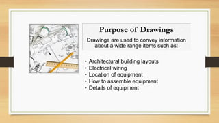
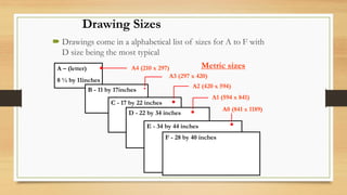
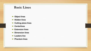
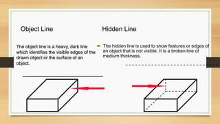
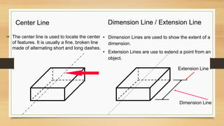
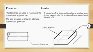
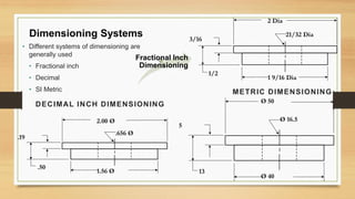
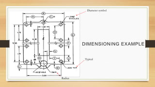
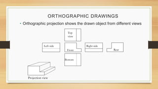
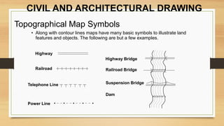
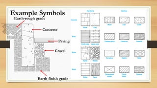
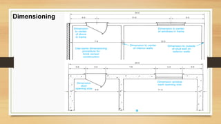
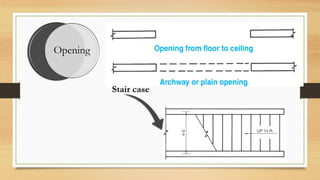
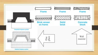
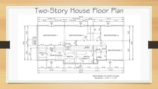
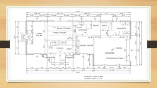
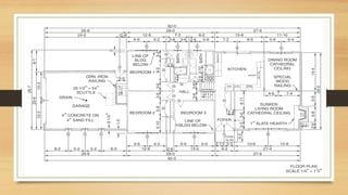
HOW
TO READ
ENGINEERING
DRAWINGS
(CIVIL & Architectural Drawings)
SUBJECTS:
DRAWING BASICS
CIVIL & ARCHITECTURAL
DRAWINGS
Purpose of Drawings
Drawings are used to convey information
about a wide range items such as:
• Architectural building layouts
• Electrical wiring
• Location of equipment
• How to assemble equipment
• Details of equipment
A – (letter)
8 ½ by 11inches
Drawing Sizes
 Drawings come in a alphabetical list of sizes for A to F with
D size being the most typical
B - 11 by 17inches
C - 17 by 22 inches
D - 22 by 34 inches
E - 34 by 44 inches
F - 28 by 40 inches
Metric sizesA4 (210 x 297)
A3 (297 x 420)
A2 (420 x 594)
A1 (594 x 841)
A0 (841 x 1189)
Basic Lines
 Object lines
 Hidden lines
 Cutting plane lines
 Centerlines
 Extension lines
 Dimension lines
 Leaders line
 Phantom lines
Object Line
The object line is a heavy, dark line
which identifies the visible edges of the
drawn object or the surface of an
object.
Hidden Line
 The hidden line is used to show features or edges of
an object that is not visible. It is a broken line of
medium thickness.
Center Line
 The center line is used to locate the center
of features. It is usually a fine, broken line
made of alternating short and long dashes.
Dimension Line / Extension Line
• Dimension Lines are used to show the extent of a
dimension.
• Extension Lines are use to extend a point from an
object.
Dimension Line
Extension Line
Phantom
• Phantom lines are used to represents the
outline of an adjacent part.
• The also are used to show an alternate
position of a given part
Phantom
Leader
• A leader is a fine line used to define a point or area.
It may have a note, dimension value or a number at
the end of it
Grind Surface
1
CUTTING PLANE LINE
• Cutting plane lines are used to indicate where an
imaginary cut is made through the object. If it is
labeled the section may be redrawn in detail in
another part of the drawing.
A A
BREAK LINES
• Short Break Line
 Break lines are also used to separate
internal and external features with
broken-out sections
 Break lines are uses to terminate a
view to conserve drawing space and
avoid congestion.
• Section lines are used where a surface is illustrated as cut.
• It normally is used in a sectional view.
• The lines are normally drawn diagonally.
SECTION LINES
Dimensioning Systems
• Different systems of dimensioning are
generally used
• Fractional inch
• Decimal
• SI Metric
2 Dia
21/32 Dia
3/16
1/2
1 9/16 Dia
DECIMAL INCH DIMENSIONING
2.00 Ø
.656 Ø
.19
.50
1.56 Ø
METRIC DIMENSIONING
Ø 50
Ø 16.5
5
13
Ø 40
Fractional Inch
Dimensioning
DIMENSIONING EXAMPLE
Diameter symbol
Radius
Typical
ORTHOGRAPHIC DRAWINGS
• Orthographic projection shows the drawn object from different views
Top
view
Left side Right side
Bottom
Front Rear
Projection view
CIVIL AND ARCHITECTURAL DRAWING
Topographical Map Symbols
• Along with contour lines maps have many basic symbols to illustrate land
features and objects. The following are but a few examples.
Highway
Railroad
Highway Bridge
Railroad Bridge
Suspension Bridge
Dam
Telephone Line
Power Line
Example Symbols
Gravel
Paving
Concrete
Earth-finish grade
Earth-rough grade
Dimensioning
Opening
Stair case
Wall
material
Fire
place
Two-Story House Floor Plan
How to read engineering drawings

How to read engineering drawings

  • 1.
  • 2.
    SUBJECTS: DRAWING BASICS CIVIL &ARCHITECTURAL DRAWINGS
  • 3.
    Purpose of Drawings Drawingsare used to convey information about a wide range items such as: • Architectural building layouts • Electrical wiring • Location of equipment • How to assemble equipment • Details of equipment
  • 4.
    A – (letter) 8½ by 11inches Drawing Sizes  Drawings come in a alphabetical list of sizes for A to F with D size being the most typical B - 11 by 17inches C - 17 by 22 inches D - 22 by 34 inches E - 34 by 44 inches F - 28 by 40 inches Metric sizesA4 (210 x 297) A3 (297 x 420) A2 (420 x 594) A1 (594 x 841) A0 (841 x 1189)
  • 5.
    Basic Lines  Objectlines  Hidden lines  Cutting plane lines  Centerlines  Extension lines  Dimension lines  Leaders line  Phantom lines
  • 6.
    Object Line The objectline is a heavy, dark line which identifies the visible edges of the drawn object or the surface of an object. Hidden Line  The hidden line is used to show features or edges of an object that is not visible. It is a broken line of medium thickness.
  • 7.
    Center Line  Thecenter line is used to locate the center of features. It is usually a fine, broken line made of alternating short and long dashes. Dimension Line / Extension Line • Dimension Lines are used to show the extent of a dimension. • Extension Lines are use to extend a point from an object. Dimension Line Extension Line
  • 8.
    Phantom • Phantom linesare used to represents the outline of an adjacent part. • The also are used to show an alternate position of a given part Phantom Leader • A leader is a fine line used to define a point or area. It may have a note, dimension value or a number at the end of it Grind Surface 1
  • 9.
    CUTTING PLANE LINE •Cutting plane lines are used to indicate where an imaginary cut is made through the object. If it is labeled the section may be redrawn in detail in another part of the drawing. A A BREAK LINES • Short Break Line  Break lines are also used to separate internal and external features with broken-out sections  Break lines are uses to terminate a view to conserve drawing space and avoid congestion.
  • 10.
    • Section linesare used where a surface is illustrated as cut. • It normally is used in a sectional view. • The lines are normally drawn diagonally. SECTION LINES
  • 11.
    Dimensioning Systems • Differentsystems of dimensioning are generally used • Fractional inch • Decimal • SI Metric 2 Dia 21/32 Dia 3/16 1/2 1 9/16 Dia DECIMAL INCH DIMENSIONING 2.00 Ø .656 Ø .19 .50 1.56 Ø METRIC DIMENSIONING Ø 50 Ø 16.5 5 13 Ø 40 Fractional Inch Dimensioning
  • 12.
  • 13.
    ORTHOGRAPHIC DRAWINGS • Orthographicprojection shows the drawn object from different views Top view Left side Right side Bottom Front Rear Projection view
  • 14.
    CIVIL AND ARCHITECTURALDRAWING Topographical Map Symbols • Along with contour lines maps have many basic symbols to illustrate land features and objects. The following are but a few examples. Highway Railroad Highway Bridge Railroad Bridge Suspension Bridge Dam Telephone Line Power Line
  • 15.
  • 16.
  • 17.
  • 18.
  • 19.