SlideShare a Scribd company logo
1 of 18
Download to read offline
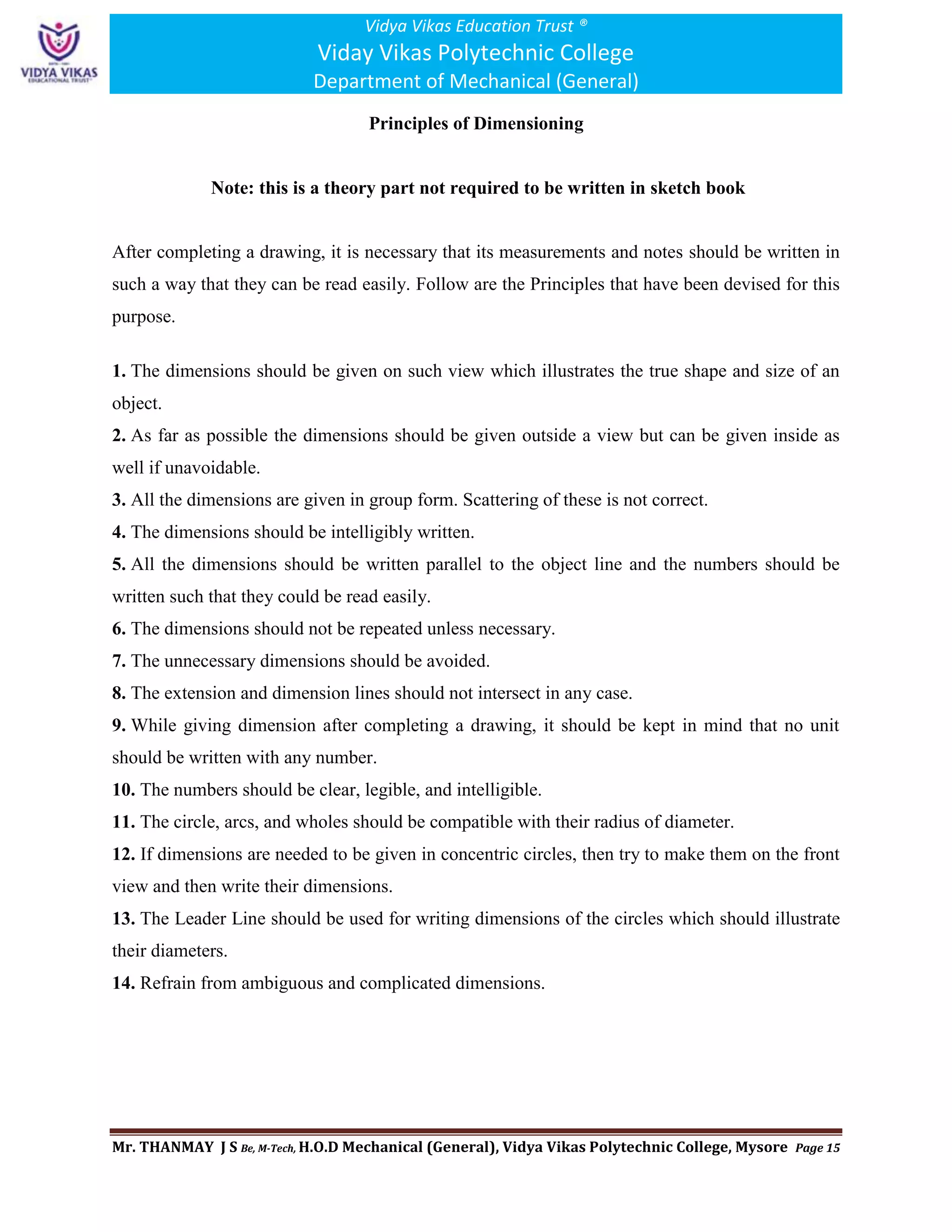
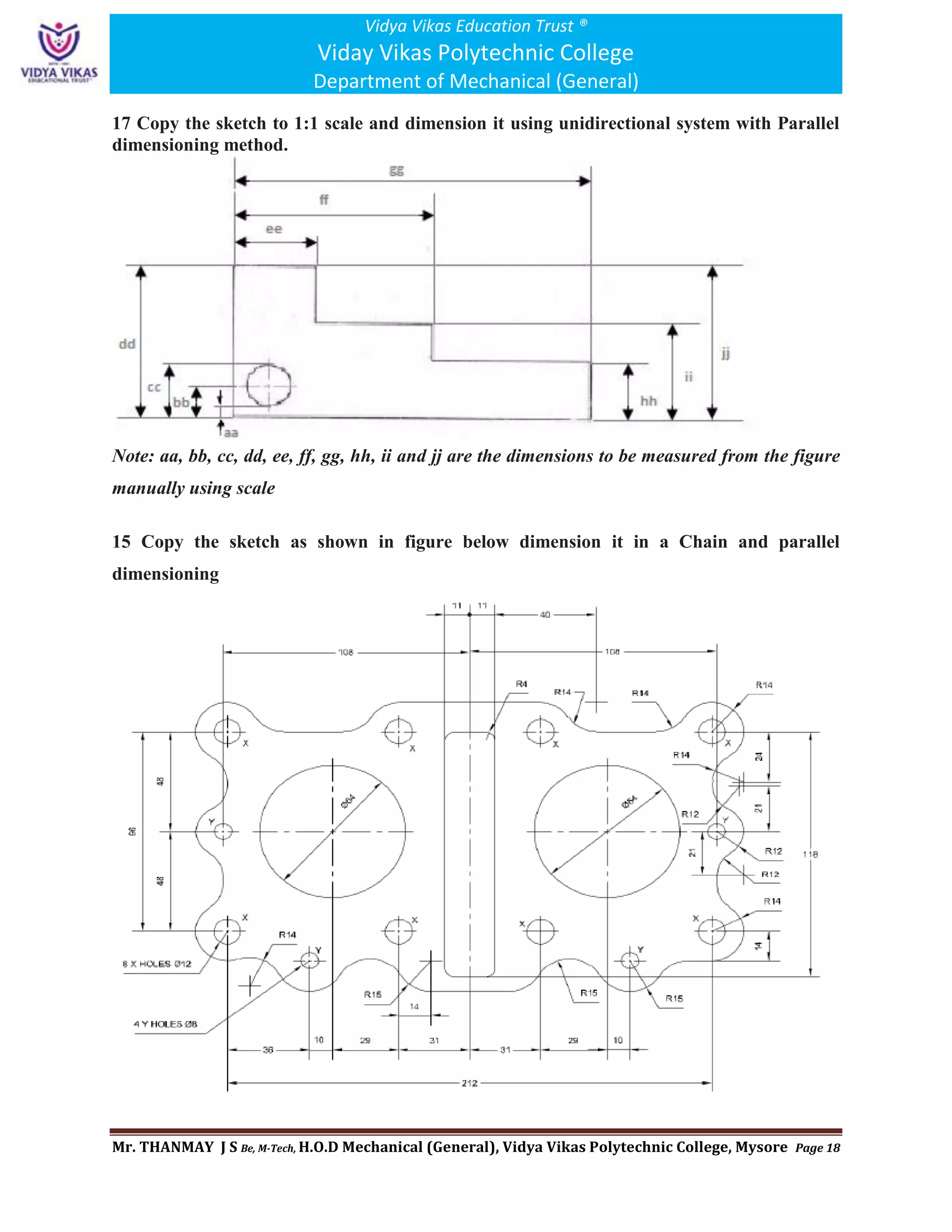
Vidya Vikas Education Trust ®
Viday Vikas Polytechnic College
Department of Mechanical (General)
Mr. THANMAY J S Be, M-Tech, H.O.D Mechanical (General), Vidya Vikas Polytechnic College, Mysore Page 1
Computer Aided Engineering Drawing (20ME12P)
Unit 1-Part 01
1. a) Illustrate the elements of dimensioning with the help of a sketch.
Elements of Dimensioning:
For any drawing to be workable, it is necessary that all the needful dimensions should be written
on it, so that all information could be used properly. For this purpose, the following elements are
written down.
1. Dimension Line.
2. Extension Line.
3. Center Line.
4. Leader Line.
5. Arrow Head.
6. Numbers.
1. Dimension Line:
A Dimension Line is drawn for a given dimension of an object. This line should be at a distance
from 10 mm to 15 mm from the object line. For writing a dimension, this line is broken from the
middle, and the dimension is written in the middle space. Alternatively, the dimension is written
on it after its completion. 2H or 4H pencil is used for this purpose.
2. Extension Line:
Such lines which are drawn extending from the ends of a part of a drawing so that the dimension
can be written in between them are called extension lines. 2H or 4H pencil is used for this
purpose. There should be a distance of 1 mm between them and the object line.
3. Center Line:
Such a line is used to represent the center of a cylindrical part of a drawing. For example, a hole
shaft, etc. This should be extended up to 1 mm distance from the object line.
4. Leader Line:
Any note or specification is written on an object with the help of this line. This is drawn with 2H
or 4H Pencil. It consists of a circle and a leader.
5. Arrow Head:
This is used at the ends of a dimension and the end of a leader. The length of the arrow-head
used in engineering drawing 3 mm.
6. Numbers:
After the completion of any geometric shape of an object, the writing of its size is desired.
Numbers are used for this purpose. The height of the number is kept 3 mm.
Vidya Vikas Education Trust ®
Viday Vikas Polytechnic College
Department of Mechanical (General)
Mr. THANMAY J S Be, M-Tech, H.O.D Mechanical (General), Vidya Vikas Polytechnic College, Mysore Page 2
Figure: Example for Elements of Dimensioning
1. b) Illustrate the dimensioning of given common features: diameter, radius, chord,
Arc and angle.
i) Dimensioning diameters
Circular features like cylindrical parts like
shafts, pipes, rods or any other round shape are
always dimensioned by indicating their
diameter. The diameter is indicated by the
symbol ∅. The diameters on the circular
objects may be indicated in any one of the
following ways as shown in fig.
Note: All Dimensions are in millimeters.
ii) Dimensioning Radius
The curved, fillets and round figures are shown
in drawings by arcs or circles. The
dimensioning is done by giving radii. The
measured radius is indicated by letter R. The
dimension line is drawn radial with the
arrowhead touching the arc.
Note: All Dimensions are in millimeters.
Vidya Vikas Education Trust ®
Viday Vikas Polytechnic College
Department of Mechanical (General)
Mr. THANMAY J S Be, M-Tech, H.O.D Mechanical (General), Vidya Vikas Polytechnic College, Mysore Page 3
iii) Dimensioning Arcs
When dimensioning the length of an arc the
dimension figure identified by symbol being
written above the dimension.
Note: All Dimensions are in millimeters.
iv) Dimensioning Chords
It is a linear distance between any two points
of an arc. And it is dimensioned as shown in
the figure.
Note: All Dimensions are in millimeters.
v) Dimensioning Angles
The angles are dimensioned in the same
manner as that of linear dimensions.
Note: All Dimensions are in millimeters.
2. a) Mention the uses of the following drawing instruments.
i) T-square
T square is used to draw horizontal and vertical lines on
drawing sheet. It made of wood or plastic and in T shape. The
vertical part of T is called as blade and horizontal part of T is
called as head. The edge of head is uniform level and attached
to the edge of the board. The working edge is used to draw
lines anywhere on the sheet by moving the instrument top to
bottom. Note: Free Hand Sketch
ii) Set square
Set squares are used to draw lines with an angle between
them. In most of the structures, 30, 45, 60 and 90-degree lines
are most common. Generally, set squares are of two types.
One is 45 degree set square and another one is called as 30 –
60 degree set square. Note: Free Hand Sketch
Vidya Vikas Education Trust ®
Viday Vikas Polytechnic College
Department of Mechanical (General)
Mr. THANMAY J S Be, M-Tech, H.O.D Mechanical (General), Vidya Vikas Polytechnic College, Mysore Page 4
iii) Bow compass
A small pair of compasses one leg of which carries a pencil,
pen, or point, its legs being connected by a bow-shaped spring
instead of by a joint. Compass is used to draw an arc or circle
with known dimensions on engineering drawing. The needle
tip is placed at the respected point and pencil tip is adjusted to
the height at least 1mm just above the tip of the needle. The
gap is nothing but the paper thickness. Note: Free Hand
Sketch
iv) Clinograph
Clinograph is an instrument used to draw parallel lines to the
inclined lines. It contains one adjustable wing or strip which
can be adjusted to required angle. So, it can be termed as
adjustable set square. Note: Free Hand Sketch
v) Mini drafter or Drafting Machine
Mini drafter is an instrument which can be used for multiple
functions in drawing. It contains two arms which are
adjustable to required angle and at the end of the lower arm a
scale set is attached. The scale set contains two scales
connected perpendicular to each which cannot be separated.
This instrument is fixed to the drawing board at one edge
with the help of screw provided for the drafter. Mini drafter
is used for drawing horizontal lines, vertical lines, inclined
lines, angles, parallel lines, perpendicular lines etc. Note:
Free Hand Sketch
2. b) Mention the uses of the following drawing instruments.
i) French curves
French curves are made of plastic and they are in
irregular shapes. Sometimes the drawing requires
irregular curves or shapes or arcs which cannot be
drawn using compass. Generally French curves are
more suitable for small curves and for long curves
splines are used. Note: Free Hand Sketch
Vidya Vikas Education Trust ®
Viday Vikas Polytechnic College
Department of Mechanical (General)
Mr. THANMAY J S Be, M-Tech, H.O.D Mechanical (General), Vidya Vikas Polytechnic College, Mysore Page 5
ii) Protractor
Protractor is used to draw and measure the angles of
lines in the drawing. It is transparent and made of
plastic. It is in the shape of semi-circle, and the edge
of semi-circle part consists reading with one-degree
accuracy. The bottom line joins the 0o
to the 180o
.
The center of this bottom line is marked as “O” or
“C” from which the angles are measured. Note: Free
Hand Sketch
iii)Clips
The clips are used to hold the drawing sheet on the
drawing board properly. Generally, 4 clips are used
for any drawing sheet. Note: Free Hand Sketch
iv)Erasing Shield
An eraser shield is a thin sheet of stainless steel or
plastic with slots and holes of different shapes. They
are designed to allow erasers to be used through them
to erase lines and text without removing lines close
by which do not need to be (or should not be) erased.
They are about the size of a business card but the
shape of the slots depends on the manufacturer. Some
stainless eraser shields are made of see-through steel
mesh so that the sections to be erased are easy to see.
Note: Free Hand Sketch
vi) Drafting machine-Same as Mini Drafter
Vidya Vikas Education Trust ®
Viday Vikas Polytechnic College
Department of Mechanical (General)
Mr. THANMAY J S Be, M-Tech, H.O.D Mechanical (General), Vidya Vikas Polytechnic College, Mysore Page 6
3. Define RF. Mention the types of scales based on RF.
Representative fraction is the ratio of the length of the object represented on drawing to the
actual length of the object represented.
There are three types of scales depending upon the proportion it indicates as
1. Reducing scale: When the dimensions on the drawing are smaller than the actual dimensions
of the object. It is represented by the scale and R.F as
Scale: - 1cm=100cm or 1:100 and by R.F=1/100 (less than one)
2. Full scale: Sometimes the actual dimensions of the object will be adopted on the drawing then
in that case it is represented by the scale and RF as
Scale: - 1cm = 1cm or 1:1 and by R.F=1/1 (equal to one).
3. Enlarging scale: In some cases when the objects are very small like inside parts of a wrist
watch, the dimensions adopted on the drawing will be bigger than the actual dimensions of the
objects then in that case it is represented by scale and RF as
Scale: - 10cm=1cm or 10:1 and by R.F= 10/1 (greater than one)
Note: The scale or R.F of a drawing is given usually below the drawing. If the scale adopted is
common for all drawings on that particular sheet, then it is given commonly for all figures under
the title of sheet.
Vidya Vikas Education Trust ®
Viday Vikas Polytechnic College
Department of Mechanical (General)
Mr. THANMAY J S Be, M-Tech, H.O.D Mechanical (General), Vidya Vikas Polytechnic College, Mysore Page 7
4. Draw the conventional representation of lines
A; Continuous Thick Line: Surroundings and sides of the matters (Outlines of the Edges), End
of the Screws,
B; Continuous Thin line: Measure lines, Backside section lines, Implied axis lines, to state the
code of the planes, at diagonal lines which are used to state plane surface, Intersection, Leader,
Hatching.
C; Free Hand Line: Limits of partial and interrupted views and sections
D; Continuous Thin Zigzag Line: It is used when free hand lines are drawn by tools
E; Dashed Thick Lines with Dots: to state the special places / surfaces this will process
additionally like to coat, to harden etc.
F; Dashed Thin Lines: Invisible/Hidden Lines represents an invisible edges on the on an
objects.
G; Chain thin: Axis lines of symmetrical drawings, In front of section planes.
K; Chain Thin with Thick Ends: Cutting Plane, to draw the trace at section planes,
Vidya Vikas Education Trust ®
Viday Vikas Polytechnic College
Department of Mechanical (General)
Mr. THANMAY J S Be, M-Tech, H.O.D Mechanical (General), Vidya Vikas Polytechnic College, Mysore Page 8
5 Draw six horizontal parallel lines of 50 mm long with 10 mm intervals (Fig 1).
6 Draw six vertical parallel lines of 50 mm length with 10 mm intervals (Fig 2)
7 Draw 45° inclined lines (Fig 3). A to B 90 mm and B to C 6o mm Note each division 10
mm
Vidya Vikas Education Trust ®
Viday Vikas Polytechnic College
Department of Mechanical (General)
Mr. THANMAY J S Be, M-Tech, H.O.D Mechanical (General), Vidya Vikas Polytechnic College, Mysore Page 9
8 Draw the given types of lines using 0.5 range thickness of line according to the
specification (Fig 4).
Note: These types of Line are Hatching lines (B5): Hatching lines are the lines which are
Parallel or inclined. The minimum space between these lines should be more than twice the
thickness of the heaviest line in the drawing. It is recommended that these spacing should never
be less than 0.5 cm that is 5 mm.
Vidya Vikas Education Trust ®
Viday Vikas Polytechnic College
Department of Mechanical (General)
Mr. THANMAY J S Be, M-Tech, H.O.D Mechanical (General), Vidya Vikas Polytechnic College, Mysore Page 10
9 Draw the following Exercises in A4 sheet or in your Sketch book according to the
dimensions (Fig 5).
Vidya Vikas Education Trust ®
Viday Vikas Polytechnic College
Department of Mechanical (General)
Mr. THANMAY J S Be, M-Tech, H.O.D Mechanical (General), Vidya Vikas Polytechnic College, Mysore Page 11
10 Draw the pattern drawing given Figure 1, 2, 3
Note SQ stands for Square of size
Vidya Vikas Education Trust ®
Viday Vikas Polytechnic College
Department of Mechanical (General)
Mr. THANMAY J S Be, M-Tech, H.O.D Mechanical (General), Vidya Vikas Polytechnic College, Mysore Page 12
11 a) Illustrate the elements of dimensioning with the help of a sketch.
b) Illustrate the dimensioning of given common features: diameter, radius, chord,
Arc and angle.
Note: 11 a and b are repeated questions do not rewrite these two questions.
DIMENSIONING SYSTEM AND TYPES
Note: this is a theory part not required to be written in sketch book
System in Dimensioning
Following are the two systems of writing dimension.
1. Unidirectional Method.
2. Aligned Method.
1. Unidirectional Method:
This method is mostly used in
dimensioning. In this method, the whole
dimension is written in the same
direction in the whole drawing. This
direction is generally vertical.
2. Aligned Method:
In this method of dimensioning, it is
written in two directions in the whole
drawing.
It is written upward and at the right side
and is read from the bottom and right
side of a drawing.
Its advantage is this that the dimensions
can be written in the horizontal direction
which is very easy to write.
Vidya Vikas Education Trust ®
Viday Vikas Polytechnic College
Department of Mechanical (General)
Mr. THANMAY J S Be, M-Tech, H.O.D Mechanical (General), Vidya Vikas Polytechnic College, Mysore Page 13
Types of Dimensioning
1. Chain dimensioning: It is used where the possible accumulation of tolerances does not
infringe (effect) on the functional requirement of the component. Dimensioning from a
common feature is used where a number of dimensions of the same direction relate to a
common origin.
2. Parallel dimensioning: Dimensions of features are taken from one datum/common
origin and are shown parallel to other and placed, so that the dimensional values can
easily be added.
Vidya Vikas Education Trust ®
Viday Vikas Polytechnic College
Department of Mechanical (General)
Mr. THANMAY J S Be, M-Tech, H.O.D Mechanical (General), Vidya Vikas Polytechnic College, Mysore Page 14
3. Superimposed running dimensioning (Progressive dimensioning): It is a simplified
dimensioning also cumulative error is controlled. It starts from one origin with arrow
heads in one direction only. This may be used where there are space limitations and
where no legibility problems would occur. The origin indication is placed appropriately
and the opposite ends of each dimension line shall be terminated only with an arrow
head. It may be advantageous to use superimposed running dimensions in two directions.
4. Combined dimensioning: Dimensions are given in chain dimensioning and parallel
dimensioning. Common feature is combined.
Vidya Vikas Education Trust ®
Viday Vikas Polytechnic College
Department of Mechanical (General)
Mr. THANMAY J S Be, M-Tech, H.O.D Mechanical (General), Vidya Vikas Polytechnic College, Mysore Page 15
Principles of Dimensioning
Note: this is a theory part not required to be written in sketch book
After completing a drawing, it is necessary that its measurements and notes should be written in
such a way that they can be read easily. Follow are the Principles that have been devised for this
purpose.
1. The dimensions should be given on such view which illustrates the true shape and size of an
object.
2. As far as possible the dimensions should be given outside a view but can be given inside as
well if unavoidable.
3. All the dimensions are given in group form. Scattering of these is not correct.
4. The dimensions should be intelligibly written.
5. All the dimensions should be written parallel to the object line and the numbers should be
written such that they could be read easily.
6. The dimensions should not be repeated unless necessary.
7. The unnecessary dimensions should be avoided.
8. The extension and dimension lines should not intersect in any case.
9. While giving dimension after completing a drawing, it should be kept in mind that no unit
should be written with any number.
10. The numbers should be clear, legible, and intelligible.
11. The circle, arcs, and wholes should be compatible with their radius of diameter.
12. If dimensions are needed to be given in concentric circles, then try to make them on the front
view and then write their dimensions.
13. The Leader Line should be used for writing dimensions of the circles which should illustrate
their diameters.
14. Refrain from ambiguous and complicated dimensions.
Vidya Vikas Education Trust ®
Viday Vikas Polytechnic College
Department of Mechanical (General)
Mr. THANMAY J S Be, M-Tech, H.O.D Mechanical (General), Vidya Vikas Polytechnic College, Mysore Page 16
12 Copy the sketch to 1:1 scale and dimension it using Aligned system.
Note: фaa, фbb and фcc are the dimensions to be measured from the figure manually using
scale
13 Copy the sketch to 1:1 scale and dimension it using unidirectional system with Parallel
Dimensioning method.
Note: фaa, фbb, фcc, фdd, фee and фff are the dimensions to be measured from the figure
manually using scale
14 Copy the sketch to 1:1 scale and dimension it using Aligned system with Chain
dimensioning method.
Note: aa, bb, cc, dd, ee, ff, gg, hh, ii, jj and фkk are the dimensions to be measured from the
figure manually using scale
Vidya Vikas Education Trust ®
Viday Vikas Polytechnic College
Department of Mechanical (General)
Mr. THANMAY J S Be, M-Tech, H.O.D Mechanical (General), Vidya Vikas Polytechnic College, Mysore Page 17
15 Copy the sketch to 1:1 scale and dimension it using Aligned system with Parallel
dimensioning method.
Note: aa, bb, cc, dd, ee, ff, gg, hh, ii and jj are the dimensions to be measured from the figure
manually using scale
16 Copy the sketch to 1:1 scale and dimension it using unidirectional system with Chain
dimensioning method
Note: aa, bb, cc, dd, ee, ff, gg, hh, ii, jj, kk, ll and mm are the dimensions to be measured from
the figure manually using scale
Vidya Vikas Education Trust ®
Viday Vikas Polytechnic College
Department of Mechanical (General)
Mr. THANMAY J S Be, M-Tech, H.O.D Mechanical (General), Vidya Vikas Polytechnic College, Mysore Page 18
17 Copy the sketch to 1:1 scale and dimension it using unidirectional system with Parallel
dimensioning method.
Note: aa, bb, cc, dd, ee, ff, gg, hh, ii and jj are the dimensions to be measured from the figure
manually using scale
15 Copy the sketch as shown in figure below dimension it in a Chain and parallel
dimensioning

More Related Content

What's hot

Basics of Engineering Drawing and Graphics
Basics of Engineering Drawing and GraphicsBasics of Engineering Drawing and Graphics
Basics of Engineering Drawing and GraphicsJeyapoovan Thangasamy
 
Computer Aided Engineering Drawing 20ME12P Unit – 02 Part 03 - PROJECTIONS OF...
Computer Aided Engineering Drawing 20ME12P Unit – 02 Part 03 - PROJECTIONS OF...Computer Aided Engineering Drawing 20ME12P Unit – 02 Part 03 - PROJECTIONS OF...
Computer Aided Engineering Drawing 20ME12P Unit – 02 Part 03 - PROJECTIONS OF...THANMAY JS
 
BE sem 1 Engineering Graphics(E.G.) full course ppt
BE sem 1 Engineering Graphics(E.G.) full course pptBE sem 1 Engineering Graphics(E.G.) full course ppt
BE sem 1 Engineering Graphics(E.G.) full course pptDhruv Parekh
 
Engineering Graphics-Free Hand sketch
Engineering Graphics-Free Hand sketchEngineering Graphics-Free Hand sketch
Engineering Graphics-Free Hand sketchDr. Ramesh B
 
Engineering drawing chapter 01 introduction
Engineering drawing chapter 01 introductionEngineering drawing chapter 01 introduction
Engineering drawing chapter 01 introductionTalha Mughal
 
Engineering drawing practice questions first semester - 2019-2020 (1)
Engineering drawing practice questions   first semester - 2019-2020 (1)Engineering drawing practice questions   first semester - 2019-2020 (1)
Engineering drawing practice questions first semester - 2019-2020 (1)AuduJoshua1
 
Basic introduction to Engineering Drawing
Basic introduction to Engineering DrawingBasic introduction to Engineering Drawing
Basic introduction to Engineering DrawingTariku Dessie
 
Fem class notes
Fem class notesFem class notes
Fem class notesDrASSayyad
 
Engineering drawing (introduction of engineering drawing) lesson 1
Engineering drawing (introduction of engineering drawing) lesson 1Engineering drawing (introduction of engineering drawing) lesson 1
Engineering drawing (introduction of engineering drawing) lesson 1hermiraguilar
 
Introduction to engineering graphics
Introduction to engineering graphicsIntroduction to engineering graphics
Introduction to engineering graphicsSuraj Meshram
 
Engineering Drawing
Engineering DrawingEngineering Drawing
Engineering DrawingLamesaBalay1
 
Practice problemsforengineeringdrawingi 14-18
Practice problemsforengineeringdrawingi 14-18Practice problemsforengineeringdrawingi 14-18
Practice problemsforengineeringdrawingi 14-18RahulPatel895143
 
Engineering Drawing basics.ppt
Engineering Drawing basics.pptEngineering Drawing basics.ppt
Engineering Drawing basics.pptDIEMS Aurangabad
 
Introduction to Engineering Design
Introduction to Engineering DesignIntroduction to Engineering Design
Introduction to Engineering DesignNaseel Ibnu Azeez
 
ME6501 Unit 1 introduction to cad
ME6501 Unit 1 introduction to cadME6501 Unit 1 introduction to cad
ME6501 Unit 1 introduction to cadJavith Saleem
 
CASA Lab Manual.pdf
CASA Lab Manual.pdfCASA Lab Manual.pdf
CASA Lab Manual.pdfTHANMAY JS
 
Lesson 13-perspective-projection
Lesson 13-perspective-projectionLesson 13-perspective-projection
Lesson 13-perspective-projectioneglive
 

What's hot (20)

Basics of Engineering Drawing and Graphics
Basics of Engineering Drawing and GraphicsBasics of Engineering Drawing and Graphics
Basics of Engineering Drawing and Graphics
 
Computer Aided Engineering Drawing 20ME12P Unit – 02 Part 03 - PROJECTIONS OF...
Computer Aided Engineering Drawing 20ME12P Unit – 02 Part 03 - PROJECTIONS OF...Computer Aided Engineering Drawing 20ME12P Unit – 02 Part 03 - PROJECTIONS OF...
Computer Aided Engineering Drawing 20ME12P Unit – 02 Part 03 - PROJECTIONS OF...
 
BE sem 1 Engineering Graphics(E.G.) full course ppt
BE sem 1 Engineering Graphics(E.G.) full course pptBE sem 1 Engineering Graphics(E.G.) full course ppt
BE sem 1 Engineering Graphics(E.G.) full course ppt
 
Engineering Graphics-Free Hand sketch
Engineering Graphics-Free Hand sketchEngineering Graphics-Free Hand sketch
Engineering Graphics-Free Hand sketch
 
Engineering drawing chapter 01 introduction
Engineering drawing chapter 01 introductionEngineering drawing chapter 01 introduction
Engineering drawing chapter 01 introduction
 
Engineering drawing practice questions first semester - 2019-2020 (1)
Engineering drawing practice questions   first semester - 2019-2020 (1)Engineering drawing practice questions   first semester - 2019-2020 (1)
Engineering drawing practice questions first semester - 2019-2020 (1)
 
Basic introduction to Engineering Drawing
Basic introduction to Engineering DrawingBasic introduction to Engineering Drawing
Basic introduction to Engineering Drawing
 
Solid Modeling
Solid ModelingSolid Modeling
Solid Modeling
 
Fem class notes
Fem class notesFem class notes
Fem class notes
 
Engineering Drawing Step by step
Engineering Drawing Step by stepEngineering Drawing Step by step
Engineering Drawing Step by step
 
Engineering drawing (introduction of engineering drawing) lesson 1
Engineering drawing (introduction of engineering drawing) lesson 1Engineering drawing (introduction of engineering drawing) lesson 1
Engineering drawing (introduction of engineering drawing) lesson 1
 
Introduction to engineering graphics
Introduction to engineering graphicsIntroduction to engineering graphics
Introduction to engineering graphics
 
Engineering Drawing
Engineering DrawingEngineering Drawing
Engineering Drawing
 
Practice problemsforengineeringdrawingi 14-18
Practice problemsforengineeringdrawingi 14-18Practice problemsforengineeringdrawingi 14-18
Practice problemsforengineeringdrawingi 14-18
 
Engineering Drawing basics.ppt
Engineering Drawing basics.pptEngineering Drawing basics.ppt
Engineering Drawing basics.ppt
 
Introduction to Engineering Design
Introduction to Engineering DesignIntroduction to Engineering Design
Introduction to Engineering Design
 
ME6501 Unit 1 introduction to cad
ME6501 Unit 1 introduction to cadME6501 Unit 1 introduction to cad
ME6501 Unit 1 introduction to cad
 
4.scale engineering108.com
4.scale engineering108.com4.scale engineering108.com
4.scale engineering108.com
 
CASA Lab Manual.pdf
CASA Lab Manual.pdfCASA Lab Manual.pdf
CASA Lab Manual.pdf
 
Lesson 13-perspective-projection
Lesson 13-perspective-projectionLesson 13-perspective-projection
Lesson 13-perspective-projection
 

Similar to Computer Aided Engineering Drawing 20ME12P DTE Karnataka

Notes-Engineering-Graphics-and-Design-1-.pdf
Notes-Engineering-Graphics-and-Design-1-.pdfNotes-Engineering-Graphics-and-Design-1-.pdf
Notes-Engineering-Graphics-and-Design-1-.pdfAlFakir Fikri AlTakiri
 
Engineering drawing
Engineering drawingEngineering drawing
Engineering drawingGopalaRaoT
 
Engineeringl drawing lecture
Engineeringl drawing lectureEngineeringl drawing lecture
Engineeringl drawing lectureSajid Yasin
 
1 SRI RANGA ITI ED 1ST&2ND CHAPTER.ppsx
1 SRI RANGA ITI ED 1ST&2ND CHAPTER.ppsx1 SRI RANGA ITI ED 1ST&2ND CHAPTER.ppsx
1 SRI RANGA ITI ED 1ST&2ND CHAPTER.ppsxravikumarHC
 
Engineering Graphics PPT.pdf
Engineering Graphics PPT.pdfEngineering Graphics PPT.pdf
Engineering Graphics PPT.pdfssuseraaeed1
 
Introduction to Engineering Graphics
Introduction to Engineering Graphics Introduction to Engineering Graphics
Introduction to Engineering Graphics Nitin Shekapure
 
Introduction to engineering graphics
Introduction to engineering graphics Introduction to engineering graphics
Introduction to engineering graphics mansi acharya
 
Lecture week 5
Lecture week 5Lecture week 5
Lecture week 5Engr umar
 
CIVIL Engineering Drawing by haseeb muhammad
CIVIL Engineering Drawing by haseeb muhammadCIVIL Engineering Drawing by haseeb muhammad
CIVIL Engineering Drawing by haseeb muhammadhaseeb mohd
 
Lecture week 5
Lecture week 5Lecture week 5
Lecture week 5Engr umar
 
Eg unit 1 1
Eg unit 1 1Eg unit 1 1
Eg unit 1 1Sundra3
 
Types of Technical & Engineering Drawing Lines and Their Uses
Types of Technical & Engineering Drawing Lines and Their UsesTypes of Technical & Engineering Drawing Lines and Their Uses
Types of Technical & Engineering Drawing Lines and Their Usesterihagh
 
Eg unit 1 1
Eg unit 1 1Eg unit 1 1
Eg unit 1 1Sundra3
 
Graphic representation of technical projects
Graphic representation of technical projectsGraphic representation of technical projects
Graphic representation of technical projectsgabriela-technoteacher
 
Drawing presentation 2015 2016
Drawing presentation 2015 2016Drawing presentation 2015 2016
Drawing presentation 2015 2016muralbe1
 
Basics of engineering drawing part 4 v4
Basics of engineering drawing part 4 v4Basics of engineering drawing part 4 v4
Basics of engineering drawing part 4 v4AISSMS IOIT,PUNE
 

Similar to Computer Aided Engineering Drawing 20ME12P DTE Karnataka (20)

Notes-Engineering-Graphics-and-Design-1-.pdf
Notes-Engineering-Graphics-and-Design-1-.pdfNotes-Engineering-Graphics-and-Design-1-.pdf
Notes-Engineering-Graphics-and-Design-1-.pdf
 
Engineering drawing
Engineering drawingEngineering drawing
Engineering drawing
 
Engineeringl drawing lecture
Engineeringl drawing lectureEngineeringl drawing lecture
Engineeringl drawing lecture
 
unit-i.pdf
unit-i.pdfunit-i.pdf
unit-i.pdf
 
1 SRI RANGA ITI ED 1ST&2ND CHAPTER.ppsx
1 SRI RANGA ITI ED 1ST&2ND CHAPTER.ppsx1 SRI RANGA ITI ED 1ST&2ND CHAPTER.ppsx
1 SRI RANGA ITI ED 1ST&2ND CHAPTER.ppsx
 
Engineering Graphics PPT.pdf
Engineering Graphics PPT.pdfEngineering Graphics PPT.pdf
Engineering Graphics PPT.pdf
 
Introduction to Engineering Graphics
Introduction to Engineering Graphics Introduction to Engineering Graphics
Introduction to Engineering Graphics
 
Introduction to engineering graphics
Introduction to engineering graphics Introduction to engineering graphics
Introduction to engineering graphics
 
Introduction to Engineering Drawing
Introduction to Engineering Drawing Introduction to Engineering Drawing
Introduction to Engineering Drawing
 
1
11
1
 
Lecture week 5
Lecture week 5Lecture week 5
Lecture week 5
 
CIVIL Engineering Drawing by haseeb muhammad
CIVIL Engineering Drawing by haseeb muhammadCIVIL Engineering Drawing by haseeb muhammad
CIVIL Engineering Drawing by haseeb muhammad
 
Lecture week 5
Lecture week 5Lecture week 5
Lecture week 5
 
Eg unit 1 1
Eg unit 1 1Eg unit 1 1
Eg unit 1 1
 
Types of Technical & Engineering Drawing Lines and Their Uses
Types of Technical & Engineering Drawing Lines and Their UsesTypes of Technical & Engineering Drawing Lines and Their Uses
Types of Technical & Engineering Drawing Lines and Their Uses
 
Eg unit 1 1
Eg unit 1 1Eg unit 1 1
Eg unit 1 1
 
Graphic representation of technical projects
Graphic representation of technical projectsGraphic representation of technical projects
Graphic representation of technical projects
 
Drawing presentation 2015 2016
Drawing presentation 2015 2016Drawing presentation 2015 2016
Drawing presentation 2015 2016
 
Basics of engineering drawing part 4 v4
Basics of engineering drawing part 4 v4Basics of engineering drawing part 4 v4
Basics of engineering drawing part 4 v4
 
Drawing reading and measurements
Drawing reading and measurementsDrawing reading and measurements
Drawing reading and measurements
 

More from THANMAY JS

Multimedia and Animation 20CS21P Portfolio.pdf
Multimedia and Animation 20CS21P Portfolio.pdfMultimedia and Animation 20CS21P Portfolio.pdf
Multimedia and Animation 20CS21P Portfolio.pdfTHANMAY JS
 
Fundamentals of Automation Technology 20EE43P Portfolio.pdf
Fundamentals of Automation Technology 20EE43P Portfolio.pdfFundamentals of Automation Technology 20EE43P Portfolio.pdf
Fundamentals of Automation Technology 20EE43P Portfolio.pdfTHANMAY JS
 
Elements of Industrial Automation Portfolio.pdf
Elements of Industrial Automation Portfolio.pdfElements of Industrial Automation Portfolio.pdf
Elements of Industrial Automation Portfolio.pdfTHANMAY JS
 
Fundamentals of Computer 20CS11T Chapter 5.pdf
Fundamentals of Computer 20CS11T Chapter 5.pdfFundamentals of Computer 20CS11T Chapter 5.pdf
Fundamentals of Computer 20CS11T Chapter 5.pdfTHANMAY JS
 
Fundamentals of Computer 20CS11T Chapter 4.pdf
Fundamentals of Computer 20CS11T Chapter 4.pdfFundamentals of Computer 20CS11T Chapter 4.pdf
Fundamentals of Computer 20CS11T Chapter 4.pdfTHANMAY JS
 
Fundamentals of Computer 20CS11T Chapter 3.pdf
Fundamentals of Computer 20CS11T Chapter 3.pdfFundamentals of Computer 20CS11T Chapter 3.pdf
Fundamentals of Computer 20CS11T Chapter 3.pdfTHANMAY JS
 
Fundamentals of Computer 20CS11T Chapter 2.pdf
Fundamentals of Computer 20CS11T Chapter 2.pdfFundamentals of Computer 20CS11T Chapter 2.pdf
Fundamentals of Computer 20CS11T Chapter 2.pdfTHANMAY JS
 
Fundamentals of Computer 20CS11T.pdf
Fundamentals of Computer 20CS11T.pdfFundamentals of Computer 20CS11T.pdf
Fundamentals of Computer 20CS11T.pdfTHANMAY JS
 
Elements of Industrial Automation Week 09 Notes.pdf
Elements of Industrial Automation Week 09 Notes.pdfElements of Industrial Automation Week 09 Notes.pdf
Elements of Industrial Automation Week 09 Notes.pdfTHANMAY JS
 
Elements of Industrial Automation Week 08 Notes.pdf
Elements of Industrial Automation Week 08 Notes.pdfElements of Industrial Automation Week 08 Notes.pdf
Elements of Industrial Automation Week 08 Notes.pdfTHANMAY JS
 
Elements of Industrial Automation Week 07 Notes.pdf
Elements of Industrial Automation Week 07 Notes.pdfElements of Industrial Automation Week 07 Notes.pdf
Elements of Industrial Automation Week 07 Notes.pdfTHANMAY JS
 
Elements of Industrial Automation Week 06 Notes.pdf
Elements of Industrial Automation Week 06 Notes.pdfElements of Industrial Automation Week 06 Notes.pdf
Elements of Industrial Automation Week 06 Notes.pdfTHANMAY JS
 
Elements of Industrial Automation Week 05 Notes.pdf
Elements of Industrial Automation Week 05 Notes.pdfElements of Industrial Automation Week 05 Notes.pdf
Elements of Industrial Automation Week 05 Notes.pdfTHANMAY JS
 
Elements of Industrial Automation Week 04 Notes.pdf
Elements of Industrial Automation Week 04 Notes.pdfElements of Industrial Automation Week 04 Notes.pdf
Elements of Industrial Automation Week 04 Notes.pdfTHANMAY JS
 
Elements of Industrial Automation Week 03 Notes.pdf
Elements of Industrial Automation Week 03 Notes.pdfElements of Industrial Automation Week 03 Notes.pdf
Elements of Industrial Automation Week 03 Notes.pdfTHANMAY JS
 
Elements of Industrial Automation Week 02 Notes.pdf
Elements of Industrial Automation Week 02 Notes.pdfElements of Industrial Automation Week 02 Notes.pdf
Elements of Industrial Automation Week 02 Notes.pdfTHANMAY JS
 
Elements of Industrial Automation Week 01 Notes.pdf
Elements of Industrial Automation Week 01 Notes.pdfElements of Industrial Automation Week 01 Notes.pdf
Elements of Industrial Automation Week 01 Notes.pdfTHANMAY JS
 
Automation and Robotics Week 08 Theory Notes 20ME51I.pdf
Automation and Robotics Week 08 Theory Notes 20ME51I.pdfAutomation and Robotics Week 08 Theory Notes 20ME51I.pdf
Automation and Robotics Week 08 Theory Notes 20ME51I.pdfTHANMAY JS
 
Automation and Robotics Week 07 Theory Notes 20ME51I.pdf
Automation and Robotics Week 07 Theory Notes 20ME51I.pdfAutomation and Robotics Week 07 Theory Notes 20ME51I.pdf
Automation and Robotics Week 07 Theory Notes 20ME51I.pdfTHANMAY JS
 
Automation and Robotics Week 06 Theory Notes 20ME51I.pdf
Automation and Robotics Week 06 Theory Notes 20ME51I.pdfAutomation and Robotics Week 06 Theory Notes 20ME51I.pdf
Automation and Robotics Week 06 Theory Notes 20ME51I.pdfTHANMAY JS
 

More from THANMAY JS (20)

Multimedia and Animation 20CS21P Portfolio.pdf
Multimedia and Animation 20CS21P Portfolio.pdfMultimedia and Animation 20CS21P Portfolio.pdf
Multimedia and Animation 20CS21P Portfolio.pdf
 
Fundamentals of Automation Technology 20EE43P Portfolio.pdf
Fundamentals of Automation Technology 20EE43P Portfolio.pdfFundamentals of Automation Technology 20EE43P Portfolio.pdf
Fundamentals of Automation Technology 20EE43P Portfolio.pdf
 
Elements of Industrial Automation Portfolio.pdf
Elements of Industrial Automation Portfolio.pdfElements of Industrial Automation Portfolio.pdf
Elements of Industrial Automation Portfolio.pdf
 
Fundamentals of Computer 20CS11T Chapter 5.pdf
Fundamentals of Computer 20CS11T Chapter 5.pdfFundamentals of Computer 20CS11T Chapter 5.pdf
Fundamentals of Computer 20CS11T Chapter 5.pdf
 
Fundamentals of Computer 20CS11T Chapter 4.pdf
Fundamentals of Computer 20CS11T Chapter 4.pdfFundamentals of Computer 20CS11T Chapter 4.pdf
Fundamentals of Computer 20CS11T Chapter 4.pdf
 
Fundamentals of Computer 20CS11T Chapter 3.pdf
Fundamentals of Computer 20CS11T Chapter 3.pdfFundamentals of Computer 20CS11T Chapter 3.pdf
Fundamentals of Computer 20CS11T Chapter 3.pdf
 
Fundamentals of Computer 20CS11T Chapter 2.pdf
Fundamentals of Computer 20CS11T Chapter 2.pdfFundamentals of Computer 20CS11T Chapter 2.pdf
Fundamentals of Computer 20CS11T Chapter 2.pdf
 
Fundamentals of Computer 20CS11T.pdf
Fundamentals of Computer 20CS11T.pdfFundamentals of Computer 20CS11T.pdf
Fundamentals of Computer 20CS11T.pdf
 
Elements of Industrial Automation Week 09 Notes.pdf
Elements of Industrial Automation Week 09 Notes.pdfElements of Industrial Automation Week 09 Notes.pdf
Elements of Industrial Automation Week 09 Notes.pdf
 
Elements of Industrial Automation Week 08 Notes.pdf
Elements of Industrial Automation Week 08 Notes.pdfElements of Industrial Automation Week 08 Notes.pdf
Elements of Industrial Automation Week 08 Notes.pdf
 
Elements of Industrial Automation Week 07 Notes.pdf
Elements of Industrial Automation Week 07 Notes.pdfElements of Industrial Automation Week 07 Notes.pdf
Elements of Industrial Automation Week 07 Notes.pdf
 
Elements of Industrial Automation Week 06 Notes.pdf
Elements of Industrial Automation Week 06 Notes.pdfElements of Industrial Automation Week 06 Notes.pdf
Elements of Industrial Automation Week 06 Notes.pdf
 
Elements of Industrial Automation Week 05 Notes.pdf
Elements of Industrial Automation Week 05 Notes.pdfElements of Industrial Automation Week 05 Notes.pdf
Elements of Industrial Automation Week 05 Notes.pdf
 
Elements of Industrial Automation Week 04 Notes.pdf
Elements of Industrial Automation Week 04 Notes.pdfElements of Industrial Automation Week 04 Notes.pdf
Elements of Industrial Automation Week 04 Notes.pdf
 
Elements of Industrial Automation Week 03 Notes.pdf
Elements of Industrial Automation Week 03 Notes.pdfElements of Industrial Automation Week 03 Notes.pdf
Elements of Industrial Automation Week 03 Notes.pdf
 
Elements of Industrial Automation Week 02 Notes.pdf
Elements of Industrial Automation Week 02 Notes.pdfElements of Industrial Automation Week 02 Notes.pdf
Elements of Industrial Automation Week 02 Notes.pdf
 
Elements of Industrial Automation Week 01 Notes.pdf
Elements of Industrial Automation Week 01 Notes.pdfElements of Industrial Automation Week 01 Notes.pdf
Elements of Industrial Automation Week 01 Notes.pdf
 
Automation and Robotics Week 08 Theory Notes 20ME51I.pdf
Automation and Robotics Week 08 Theory Notes 20ME51I.pdfAutomation and Robotics Week 08 Theory Notes 20ME51I.pdf
Automation and Robotics Week 08 Theory Notes 20ME51I.pdf
 
Automation and Robotics Week 07 Theory Notes 20ME51I.pdf
Automation and Robotics Week 07 Theory Notes 20ME51I.pdfAutomation and Robotics Week 07 Theory Notes 20ME51I.pdf
Automation and Robotics Week 07 Theory Notes 20ME51I.pdf
 
Automation and Robotics Week 06 Theory Notes 20ME51I.pdf
Automation and Robotics Week 06 Theory Notes 20ME51I.pdfAutomation and Robotics Week 06 Theory Notes 20ME51I.pdf
Automation and Robotics Week 06 Theory Notes 20ME51I.pdf
 

Recently uploaded

Porous Ceramics seminar and technical writing
Porous Ceramics seminar and technical writingPorous Ceramics seminar and technical writing
Porous Ceramics seminar and technical writingrakeshbaidya232001
 
VIP Call Girls Service Kondapur Hyderabad Call +91-8250192130
VIP Call Girls Service Kondapur Hyderabad Call +91-8250192130VIP Call Girls Service Kondapur Hyderabad Call +91-8250192130
VIP Call Girls Service Kondapur Hyderabad Call +91-8250192130Suhani Kapoor
 
Software Development Life Cycle By Team Orange (Dept. of Pharmacy)
Software Development Life Cycle By  Team Orange (Dept. of Pharmacy)Software Development Life Cycle By  Team Orange (Dept. of Pharmacy)
Software Development Life Cycle By Team Orange (Dept. of Pharmacy)Suman Mia
 
HARDNESS, FRACTURE TOUGHNESS AND STRENGTH OF CERAMICS
HARDNESS, FRACTURE TOUGHNESS AND STRENGTH OF CERAMICSHARDNESS, FRACTURE TOUGHNESS AND STRENGTH OF CERAMICS
HARDNESS, FRACTURE TOUGHNESS AND STRENGTH OF CERAMICSRajkumarAkumalla
 
Sheet Pile Wall Design and Construction: A Practical Guide for Civil Engineer...
Sheet Pile Wall Design and Construction: A Practical Guide for Civil Engineer...Sheet Pile Wall Design and Construction: A Practical Guide for Civil Engineer...
Sheet Pile Wall Design and Construction: A Practical Guide for Civil Engineer...Dr.Costas Sachpazis
 
College Call Girls Nashik Nehal 7001305949 Independent Escort Service Nashik
College Call Girls Nashik Nehal 7001305949 Independent Escort Service NashikCollege Call Girls Nashik Nehal 7001305949 Independent Escort Service Nashik
College Call Girls Nashik Nehal 7001305949 Independent Escort Service NashikCall Girls in Nagpur High Profile
 
Gfe Mayur Vihar Call Girls Service WhatsApp -> 9999965857 Available 24x7 ^ De...
Gfe Mayur Vihar Call Girls Service WhatsApp -> 9999965857 Available 24x7 ^ De...Gfe Mayur Vihar Call Girls Service WhatsApp -> 9999965857 Available 24x7 ^ De...
Gfe Mayur Vihar Call Girls Service WhatsApp -> 9999965857 Available 24x7 ^ De...srsj9000
 
(ANJALI) Dange Chowk Call Girls Just Call 7001035870 [ Cash on Delivery ] Pun...
(ANJALI) Dange Chowk Call Girls Just Call 7001035870 [ Cash on Delivery ] Pun...(ANJALI) Dange Chowk Call Girls Just Call 7001035870 [ Cash on Delivery ] Pun...
(ANJALI) Dange Chowk Call Girls Just Call 7001035870 [ Cash on Delivery ] Pun...ranjana rawat
 
chaitra-1.pptx fake news detection using machine learning
chaitra-1.pptx  fake news detection using machine learningchaitra-1.pptx  fake news detection using machine learning
chaitra-1.pptx fake news detection using machine learningmisbanausheenparvam
 
GDSC ASEB Gen AI study jams presentation
GDSC ASEB Gen AI study jams presentationGDSC ASEB Gen AI study jams presentation
GDSC ASEB Gen AI study jams presentationGDSCAESB
 
OSVC_Meta-Data based Simulation Automation to overcome Verification Challenge...
OSVC_Meta-Data based Simulation Automation to overcome Verification Challenge...OSVC_Meta-Data based Simulation Automation to overcome Verification Challenge...
OSVC_Meta-Data based Simulation Automation to overcome Verification Challenge...Soham Mondal
 
Call Girls Delhi {Jodhpur} 9711199012 high profile service
Call Girls Delhi {Jodhpur} 9711199012 high profile serviceCall Girls Delhi {Jodhpur} 9711199012 high profile service
Call Girls Delhi {Jodhpur} 9711199012 high profile servicerehmti665
 
the ladakh protest in leh ladakh 2024 sonam wangchuk.pptx
the ladakh protest in leh ladakh 2024 sonam wangchuk.pptxthe ladakh protest in leh ladakh 2024 sonam wangchuk.pptx
the ladakh protest in leh ladakh 2024 sonam wangchuk.pptxhumanexperienceaaa
 
MANUFACTURING PROCESS-II UNIT-2 LATHE MACHINE
MANUFACTURING PROCESS-II UNIT-2 LATHE MACHINEMANUFACTURING PROCESS-II UNIT-2 LATHE MACHINE
MANUFACTURING PROCESS-II UNIT-2 LATHE MACHINESIVASHANKAR N
 
High Profile Call Girls Nagpur Isha Call 7001035870 Meet With Nagpur Escorts
High Profile Call Girls Nagpur Isha Call 7001035870 Meet With Nagpur EscortsHigh Profile Call Girls Nagpur Isha Call 7001035870 Meet With Nagpur Escorts
High Profile Call Girls Nagpur Isha Call 7001035870 Meet With Nagpur Escortsranjana rawat
 
Structural Analysis and Design of Foundations: A Comprehensive Handbook for S...
Structural Analysis and Design of Foundations: A Comprehensive Handbook for S...Structural Analysis and Design of Foundations: A Comprehensive Handbook for S...
Structural Analysis and Design of Foundations: A Comprehensive Handbook for S...Dr.Costas Sachpazis
 

Recently uploaded (20)

Porous Ceramics seminar and technical writing
Porous Ceramics seminar and technical writingPorous Ceramics seminar and technical writing
Porous Ceramics seminar and technical writing
 
VIP Call Girls Service Kondapur Hyderabad Call +91-8250192130
VIP Call Girls Service Kondapur Hyderabad Call +91-8250192130VIP Call Girls Service Kondapur Hyderabad Call +91-8250192130
VIP Call Girls Service Kondapur Hyderabad Call +91-8250192130
 
Software Development Life Cycle By Team Orange (Dept. of Pharmacy)
Software Development Life Cycle By  Team Orange (Dept. of Pharmacy)Software Development Life Cycle By  Team Orange (Dept. of Pharmacy)
Software Development Life Cycle By Team Orange (Dept. of Pharmacy)
 
HARDNESS, FRACTURE TOUGHNESS AND STRENGTH OF CERAMICS
HARDNESS, FRACTURE TOUGHNESS AND STRENGTH OF CERAMICSHARDNESS, FRACTURE TOUGHNESS AND STRENGTH OF CERAMICS
HARDNESS, FRACTURE TOUGHNESS AND STRENGTH OF CERAMICS
 
Sheet Pile Wall Design and Construction: A Practical Guide for Civil Engineer...
Sheet Pile Wall Design and Construction: A Practical Guide for Civil Engineer...Sheet Pile Wall Design and Construction: A Practical Guide for Civil Engineer...
Sheet Pile Wall Design and Construction: A Practical Guide for Civil Engineer...
 
DJARUM4D - SLOT GACOR ONLINE | SLOT DEMO ONLINE
DJARUM4D - SLOT GACOR ONLINE | SLOT DEMO ONLINEDJARUM4D - SLOT GACOR ONLINE | SLOT DEMO ONLINE
DJARUM4D - SLOT GACOR ONLINE | SLOT DEMO ONLINE
 
College Call Girls Nashik Nehal 7001305949 Independent Escort Service Nashik
College Call Girls Nashik Nehal 7001305949 Independent Escort Service NashikCollege Call Girls Nashik Nehal 7001305949 Independent Escort Service Nashik
College Call Girls Nashik Nehal 7001305949 Independent Escort Service Nashik
 
Gfe Mayur Vihar Call Girls Service WhatsApp -> 9999965857 Available 24x7 ^ De...
Gfe Mayur Vihar Call Girls Service WhatsApp -> 9999965857 Available 24x7 ^ De...Gfe Mayur Vihar Call Girls Service WhatsApp -> 9999965857 Available 24x7 ^ De...
Gfe Mayur Vihar Call Girls Service WhatsApp -> 9999965857 Available 24x7 ^ De...
 
(ANJALI) Dange Chowk Call Girls Just Call 7001035870 [ Cash on Delivery ] Pun...
(ANJALI) Dange Chowk Call Girls Just Call 7001035870 [ Cash on Delivery ] Pun...(ANJALI) Dange Chowk Call Girls Just Call 7001035870 [ Cash on Delivery ] Pun...
(ANJALI) Dange Chowk Call Girls Just Call 7001035870 [ Cash on Delivery ] Pun...
 
Roadmap to Membership of RICS - Pathways and Routes
Roadmap to Membership of RICS - Pathways and RoutesRoadmap to Membership of RICS - Pathways and Routes
Roadmap to Membership of RICS - Pathways and Routes
 
chaitra-1.pptx fake news detection using machine learning
chaitra-1.pptx  fake news detection using machine learningchaitra-1.pptx  fake news detection using machine learning
chaitra-1.pptx fake news detection using machine learning
 
GDSC ASEB Gen AI study jams presentation
GDSC ASEB Gen AI study jams presentationGDSC ASEB Gen AI study jams presentation
GDSC ASEB Gen AI study jams presentation
 
OSVC_Meta-Data based Simulation Automation to overcome Verification Challenge...
OSVC_Meta-Data based Simulation Automation to overcome Verification Challenge...OSVC_Meta-Data based Simulation Automation to overcome Verification Challenge...
OSVC_Meta-Data based Simulation Automation to overcome Verification Challenge...
 
Call Girls Delhi {Jodhpur} 9711199012 high profile service
Call Girls Delhi {Jodhpur} 9711199012 high profile serviceCall Girls Delhi {Jodhpur} 9711199012 high profile service
Call Girls Delhi {Jodhpur} 9711199012 high profile service
 
the ladakh protest in leh ladakh 2024 sonam wangchuk.pptx
the ladakh protest in leh ladakh 2024 sonam wangchuk.pptxthe ladakh protest in leh ladakh 2024 sonam wangchuk.pptx
the ladakh protest in leh ladakh 2024 sonam wangchuk.pptx
 
Exploring_Network_Security_with_JA3_by_Rakesh Seal.pptx
Exploring_Network_Security_with_JA3_by_Rakesh Seal.pptxExploring_Network_Security_with_JA3_by_Rakesh Seal.pptx
Exploring_Network_Security_with_JA3_by_Rakesh Seal.pptx
 
MANUFACTURING PROCESS-II UNIT-2 LATHE MACHINE
MANUFACTURING PROCESS-II UNIT-2 LATHE MACHINEMANUFACTURING PROCESS-II UNIT-2 LATHE MACHINE
MANUFACTURING PROCESS-II UNIT-2 LATHE MACHINE
 
High Profile Call Girls Nagpur Isha Call 7001035870 Meet With Nagpur Escorts
High Profile Call Girls Nagpur Isha Call 7001035870 Meet With Nagpur EscortsHigh Profile Call Girls Nagpur Isha Call 7001035870 Meet With Nagpur Escorts
High Profile Call Girls Nagpur Isha Call 7001035870 Meet With Nagpur Escorts
 
Call Us -/9953056974- Call Girls In Vikaspuri-/- Delhi NCR
Call Us -/9953056974- Call Girls In Vikaspuri-/- Delhi NCRCall Us -/9953056974- Call Girls In Vikaspuri-/- Delhi NCR
Call Us -/9953056974- Call Girls In Vikaspuri-/- Delhi NCR
 
Structural Analysis and Design of Foundations: A Comprehensive Handbook for S...
Structural Analysis and Design of Foundations: A Comprehensive Handbook for S...Structural Analysis and Design of Foundations: A Comprehensive Handbook for S...
Structural Analysis and Design of Foundations: A Comprehensive Handbook for S...
 

Computer Aided Engineering Drawing 20ME12P DTE Karnataka

  • 1. Vidya Vikas Education Trust ® Viday Vikas Polytechnic College Department of Mechanical (General) Mr. THANMAY J S Be, M-Tech, H.O.D Mechanical (General), Vidya Vikas Polytechnic College, Mysore Page 1 Computer Aided Engineering Drawing (20ME12P) Unit 1-Part 01 1. a) Illustrate the elements of dimensioning with the help of a sketch. Elements of Dimensioning: For any drawing to be workable, it is necessary that all the needful dimensions should be written on it, so that all information could be used properly. For this purpose, the following elements are written down. 1. Dimension Line. 2. Extension Line. 3. Center Line. 4. Leader Line. 5. Arrow Head. 6. Numbers. 1. Dimension Line: A Dimension Line is drawn for a given dimension of an object. This line should be at a distance from 10 mm to 15 mm from the object line. For writing a dimension, this line is broken from the middle, and the dimension is written in the middle space. Alternatively, the dimension is written on it after its completion. 2H or 4H pencil is used for this purpose. 2. Extension Line: Such lines which are drawn extending from the ends of a part of a drawing so that the dimension can be written in between them are called extension lines. 2H or 4H pencil is used for this purpose. There should be a distance of 1 mm between them and the object line. 3. Center Line: Such a line is used to represent the center of a cylindrical part of a drawing. For example, a hole shaft, etc. This should be extended up to 1 mm distance from the object line. 4. Leader Line: Any note or specification is written on an object with the help of this line. This is drawn with 2H or 4H Pencil. It consists of a circle and a leader. 5. Arrow Head: This is used at the ends of a dimension and the end of a leader. The length of the arrow-head used in engineering drawing 3 mm. 6. Numbers: After the completion of any geometric shape of an object, the writing of its size is desired. Numbers are used for this purpose. The height of the number is kept 3 mm.
  • 2. Vidya Vikas Education Trust ® Viday Vikas Polytechnic College Department of Mechanical (General) Mr. THANMAY J S Be, M-Tech, H.O.D Mechanical (General), Vidya Vikas Polytechnic College, Mysore Page 2 Figure: Example for Elements of Dimensioning 1. b) Illustrate the dimensioning of given common features: diameter, radius, chord, Arc and angle. i) Dimensioning diameters Circular features like cylindrical parts like shafts, pipes, rods or any other round shape are always dimensioned by indicating their diameter. The diameter is indicated by the symbol ∅. The diameters on the circular objects may be indicated in any one of the following ways as shown in fig. Note: All Dimensions are in millimeters. ii) Dimensioning Radius The curved, fillets and round figures are shown in drawings by arcs or circles. The dimensioning is done by giving radii. The measured radius is indicated by letter R. The dimension line is drawn radial with the arrowhead touching the arc. Note: All Dimensions are in millimeters.
  • 3. Vidya Vikas Education Trust ® Viday Vikas Polytechnic College Department of Mechanical (General) Mr. THANMAY J S Be, M-Tech, H.O.D Mechanical (General), Vidya Vikas Polytechnic College, Mysore Page 3 iii) Dimensioning Arcs When dimensioning the length of an arc the dimension figure identified by symbol being written above the dimension. Note: All Dimensions are in millimeters. iv) Dimensioning Chords It is a linear distance between any two points of an arc. And it is dimensioned as shown in the figure. Note: All Dimensions are in millimeters. v) Dimensioning Angles The angles are dimensioned in the same manner as that of linear dimensions. Note: All Dimensions are in millimeters. 2. a) Mention the uses of the following drawing instruments. i) T-square T square is used to draw horizontal and vertical lines on drawing sheet. It made of wood or plastic and in T shape. The vertical part of T is called as blade and horizontal part of T is called as head. The edge of head is uniform level and attached to the edge of the board. The working edge is used to draw lines anywhere on the sheet by moving the instrument top to bottom. Note: Free Hand Sketch ii) Set square Set squares are used to draw lines with an angle between them. In most of the structures, 30, 45, 60 and 90-degree lines are most common. Generally, set squares are of two types. One is 45 degree set square and another one is called as 30 – 60 degree set square. Note: Free Hand Sketch
  • 4. Vidya Vikas Education Trust ® Viday Vikas Polytechnic College Department of Mechanical (General) Mr. THANMAY J S Be, M-Tech, H.O.D Mechanical (General), Vidya Vikas Polytechnic College, Mysore Page 4 iii) Bow compass A small pair of compasses one leg of which carries a pencil, pen, or point, its legs being connected by a bow-shaped spring instead of by a joint. Compass is used to draw an arc or circle with known dimensions on engineering drawing. The needle tip is placed at the respected point and pencil tip is adjusted to the height at least 1mm just above the tip of the needle. The gap is nothing but the paper thickness. Note: Free Hand Sketch iv) Clinograph Clinograph is an instrument used to draw parallel lines to the inclined lines. It contains one adjustable wing or strip which can be adjusted to required angle. So, it can be termed as adjustable set square. Note: Free Hand Sketch v) Mini drafter or Drafting Machine Mini drafter is an instrument which can be used for multiple functions in drawing. It contains two arms which are adjustable to required angle and at the end of the lower arm a scale set is attached. The scale set contains two scales connected perpendicular to each which cannot be separated. This instrument is fixed to the drawing board at one edge with the help of screw provided for the drafter. Mini drafter is used for drawing horizontal lines, vertical lines, inclined lines, angles, parallel lines, perpendicular lines etc. Note: Free Hand Sketch 2. b) Mention the uses of the following drawing instruments. i) French curves French curves are made of plastic and they are in irregular shapes. Sometimes the drawing requires irregular curves or shapes or arcs which cannot be drawn using compass. Generally French curves are more suitable for small curves and for long curves splines are used. Note: Free Hand Sketch
  • 5. Vidya Vikas Education Trust ® Viday Vikas Polytechnic College Department of Mechanical (General) Mr. THANMAY J S Be, M-Tech, H.O.D Mechanical (General), Vidya Vikas Polytechnic College, Mysore Page 5 ii) Protractor Protractor is used to draw and measure the angles of lines in the drawing. It is transparent and made of plastic. It is in the shape of semi-circle, and the edge of semi-circle part consists reading with one-degree accuracy. The bottom line joins the 0o to the 180o . The center of this bottom line is marked as “O” or “C” from which the angles are measured. Note: Free Hand Sketch iii)Clips The clips are used to hold the drawing sheet on the drawing board properly. Generally, 4 clips are used for any drawing sheet. Note: Free Hand Sketch iv)Erasing Shield An eraser shield is a thin sheet of stainless steel or plastic with slots and holes of different shapes. They are designed to allow erasers to be used through them to erase lines and text without removing lines close by which do not need to be (or should not be) erased. They are about the size of a business card but the shape of the slots depends on the manufacturer. Some stainless eraser shields are made of see-through steel mesh so that the sections to be erased are easy to see. Note: Free Hand Sketch vi) Drafting machine-Same as Mini Drafter
  • 6. Vidya Vikas Education Trust ® Viday Vikas Polytechnic College Department of Mechanical (General) Mr. THANMAY J S Be, M-Tech, H.O.D Mechanical (General), Vidya Vikas Polytechnic College, Mysore Page 6 3. Define RF. Mention the types of scales based on RF. Representative fraction is the ratio of the length of the object represented on drawing to the actual length of the object represented. There are three types of scales depending upon the proportion it indicates as 1. Reducing scale: When the dimensions on the drawing are smaller than the actual dimensions of the object. It is represented by the scale and R.F as Scale: - 1cm=100cm or 1:100 and by R.F=1/100 (less than one) 2. Full scale: Sometimes the actual dimensions of the object will be adopted on the drawing then in that case it is represented by the scale and RF as Scale: - 1cm = 1cm or 1:1 and by R.F=1/1 (equal to one). 3. Enlarging scale: In some cases when the objects are very small like inside parts of a wrist watch, the dimensions adopted on the drawing will be bigger than the actual dimensions of the objects then in that case it is represented by scale and RF as Scale: - 10cm=1cm or 10:1 and by R.F= 10/1 (greater than one) Note: The scale or R.F of a drawing is given usually below the drawing. If the scale adopted is common for all drawings on that particular sheet, then it is given commonly for all figures under the title of sheet.
  • 7. Vidya Vikas Education Trust ® Viday Vikas Polytechnic College Department of Mechanical (General) Mr. THANMAY J S Be, M-Tech, H.O.D Mechanical (General), Vidya Vikas Polytechnic College, Mysore Page 7 4. Draw the conventional representation of lines A; Continuous Thick Line: Surroundings and sides of the matters (Outlines of the Edges), End of the Screws, B; Continuous Thin line: Measure lines, Backside section lines, Implied axis lines, to state the code of the planes, at diagonal lines which are used to state plane surface, Intersection, Leader, Hatching. C; Free Hand Line: Limits of partial and interrupted views and sections D; Continuous Thin Zigzag Line: It is used when free hand lines are drawn by tools E; Dashed Thick Lines with Dots: to state the special places / surfaces this will process additionally like to coat, to harden etc. F; Dashed Thin Lines: Invisible/Hidden Lines represents an invisible edges on the on an objects. G; Chain thin: Axis lines of symmetrical drawings, In front of section planes. K; Chain Thin with Thick Ends: Cutting Plane, to draw the trace at section planes,
  • 8. Vidya Vikas Education Trust ® Viday Vikas Polytechnic College Department of Mechanical (General) Mr. THANMAY J S Be, M-Tech, H.O.D Mechanical (General), Vidya Vikas Polytechnic College, Mysore Page 8 5 Draw six horizontal parallel lines of 50 mm long with 10 mm intervals (Fig 1). 6 Draw six vertical parallel lines of 50 mm length with 10 mm intervals (Fig 2) 7 Draw 45° inclined lines (Fig 3). A to B 90 mm and B to C 6o mm Note each division 10 mm
  • 9. Vidya Vikas Education Trust ® Viday Vikas Polytechnic College Department of Mechanical (General) Mr. THANMAY J S Be, M-Tech, H.O.D Mechanical (General), Vidya Vikas Polytechnic College, Mysore Page 9 8 Draw the given types of lines using 0.5 range thickness of line according to the specification (Fig 4). Note: These types of Line are Hatching lines (B5): Hatching lines are the lines which are Parallel or inclined. The minimum space between these lines should be more than twice the thickness of the heaviest line in the drawing. It is recommended that these spacing should never be less than 0.5 cm that is 5 mm.
  • 10. Vidya Vikas Education Trust ® Viday Vikas Polytechnic College Department of Mechanical (General) Mr. THANMAY J S Be, M-Tech, H.O.D Mechanical (General), Vidya Vikas Polytechnic College, Mysore Page 10 9 Draw the following Exercises in A4 sheet or in your Sketch book according to the dimensions (Fig 5).
  • 11. Vidya Vikas Education Trust ® Viday Vikas Polytechnic College Department of Mechanical (General) Mr. THANMAY J S Be, M-Tech, H.O.D Mechanical (General), Vidya Vikas Polytechnic College, Mysore Page 11 10 Draw the pattern drawing given Figure 1, 2, 3 Note SQ stands for Square of size
  • 12. Vidya Vikas Education Trust ® Viday Vikas Polytechnic College Department of Mechanical (General) Mr. THANMAY J S Be, M-Tech, H.O.D Mechanical (General), Vidya Vikas Polytechnic College, Mysore Page 12 11 a) Illustrate the elements of dimensioning with the help of a sketch. b) Illustrate the dimensioning of given common features: diameter, radius, chord, Arc and angle. Note: 11 a and b are repeated questions do not rewrite these two questions. DIMENSIONING SYSTEM AND TYPES Note: this is a theory part not required to be written in sketch book System in Dimensioning Following are the two systems of writing dimension. 1. Unidirectional Method. 2. Aligned Method. 1. Unidirectional Method: This method is mostly used in dimensioning. In this method, the whole dimension is written in the same direction in the whole drawing. This direction is generally vertical. 2. Aligned Method: In this method of dimensioning, it is written in two directions in the whole drawing. It is written upward and at the right side and is read from the bottom and right side of a drawing. Its advantage is this that the dimensions can be written in the horizontal direction which is very easy to write.
  • 13. Vidya Vikas Education Trust ® Viday Vikas Polytechnic College Department of Mechanical (General) Mr. THANMAY J S Be, M-Tech, H.O.D Mechanical (General), Vidya Vikas Polytechnic College, Mysore Page 13 Types of Dimensioning 1. Chain dimensioning: It is used where the possible accumulation of tolerances does not infringe (effect) on the functional requirement of the component. Dimensioning from a common feature is used where a number of dimensions of the same direction relate to a common origin. 2. Parallel dimensioning: Dimensions of features are taken from one datum/common origin and are shown parallel to other and placed, so that the dimensional values can easily be added.
  • 14. Vidya Vikas Education Trust ® Viday Vikas Polytechnic College Department of Mechanical (General) Mr. THANMAY J S Be, M-Tech, H.O.D Mechanical (General), Vidya Vikas Polytechnic College, Mysore Page 14 3. Superimposed running dimensioning (Progressive dimensioning): It is a simplified dimensioning also cumulative error is controlled. It starts from one origin with arrow heads in one direction only. This may be used where there are space limitations and where no legibility problems would occur. The origin indication is placed appropriately and the opposite ends of each dimension line shall be terminated only with an arrow head. It may be advantageous to use superimposed running dimensions in two directions. 4. Combined dimensioning: Dimensions are given in chain dimensioning and parallel dimensioning. Common feature is combined.
  • 15. Vidya Vikas Education Trust ® Viday Vikas Polytechnic College Department of Mechanical (General) Mr. THANMAY J S Be, M-Tech, H.O.D Mechanical (General), Vidya Vikas Polytechnic College, Mysore Page 15 Principles of Dimensioning Note: this is a theory part not required to be written in sketch book After completing a drawing, it is necessary that its measurements and notes should be written in such a way that they can be read easily. Follow are the Principles that have been devised for this purpose. 1. The dimensions should be given on such view which illustrates the true shape and size of an object. 2. As far as possible the dimensions should be given outside a view but can be given inside as well if unavoidable. 3. All the dimensions are given in group form. Scattering of these is not correct. 4. The dimensions should be intelligibly written. 5. All the dimensions should be written parallel to the object line and the numbers should be written such that they could be read easily. 6. The dimensions should not be repeated unless necessary. 7. The unnecessary dimensions should be avoided. 8. The extension and dimension lines should not intersect in any case. 9. While giving dimension after completing a drawing, it should be kept in mind that no unit should be written with any number. 10. The numbers should be clear, legible, and intelligible. 11. The circle, arcs, and wholes should be compatible with their radius of diameter. 12. If dimensions are needed to be given in concentric circles, then try to make them on the front view and then write their dimensions. 13. The Leader Line should be used for writing dimensions of the circles which should illustrate their diameters. 14. Refrain from ambiguous and complicated dimensions.
  • 16. Vidya Vikas Education Trust ® Viday Vikas Polytechnic College Department of Mechanical (General) Mr. THANMAY J S Be, M-Tech, H.O.D Mechanical (General), Vidya Vikas Polytechnic College, Mysore Page 16 12 Copy the sketch to 1:1 scale and dimension it using Aligned system. Note: фaa, фbb and фcc are the dimensions to be measured from the figure manually using scale 13 Copy the sketch to 1:1 scale and dimension it using unidirectional system with Parallel Dimensioning method. Note: фaa, фbb, фcc, фdd, фee and фff are the dimensions to be measured from the figure manually using scale 14 Copy the sketch to 1:1 scale and dimension it using Aligned system with Chain dimensioning method. Note: aa, bb, cc, dd, ee, ff, gg, hh, ii, jj and фkk are the dimensions to be measured from the figure manually using scale
  • 17. Vidya Vikas Education Trust ® Viday Vikas Polytechnic College Department of Mechanical (General) Mr. THANMAY J S Be, M-Tech, H.O.D Mechanical (General), Vidya Vikas Polytechnic College, Mysore Page 17 15 Copy the sketch to 1:1 scale and dimension it using Aligned system with Parallel dimensioning method. Note: aa, bb, cc, dd, ee, ff, gg, hh, ii and jj are the dimensions to be measured from the figure manually using scale 16 Copy the sketch to 1:1 scale and dimension it using unidirectional system with Chain dimensioning method Note: aa, bb, cc, dd, ee, ff, gg, hh, ii, jj, kk, ll and mm are the dimensions to be measured from the figure manually using scale
  • 18. Vidya Vikas Education Trust ® Viday Vikas Polytechnic College Department of Mechanical (General) Mr. THANMAY J S Be, M-Tech, H.O.D Mechanical (General), Vidya Vikas Polytechnic College, Mysore Page 18 17 Copy the sketch to 1:1 scale and dimension it using unidirectional system with Parallel dimensioning method. Note: aa, bb, cc, dd, ee, ff, gg, hh, ii and jj are the dimensions to be measured from the figure manually using scale 15 Copy the sketch as shown in figure below dimension it in a Chain and parallel dimensioning