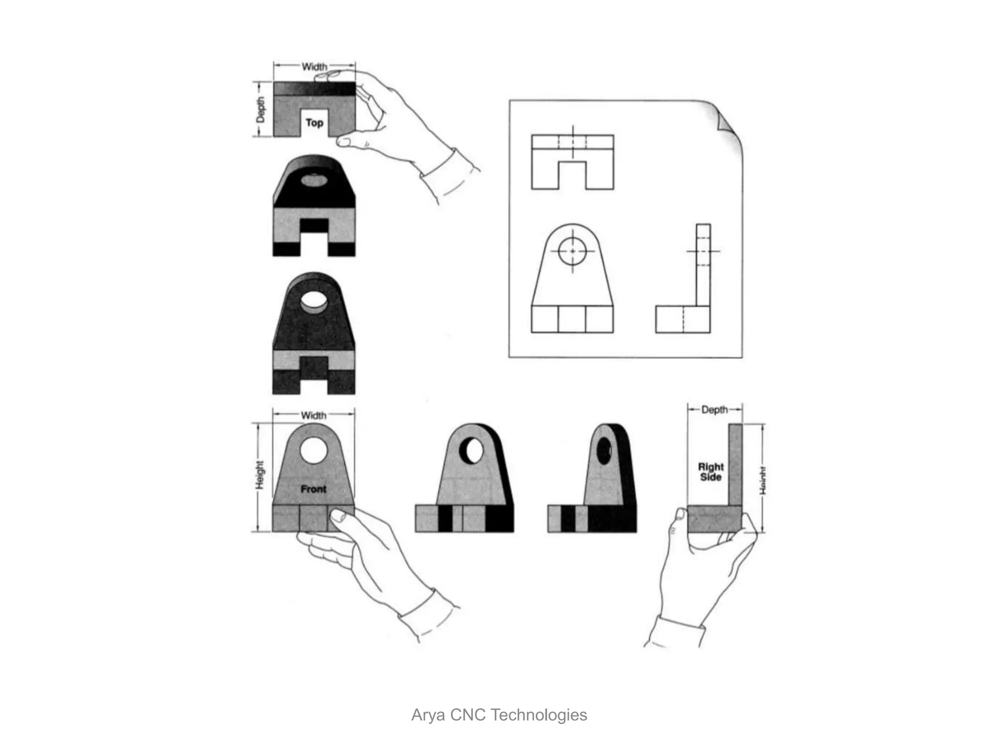
Orthographic
Projection
Arya CNC Technologies
Orthographic projection
• Orthographic" comes from the Greek word for "straight
writing (or drawing)." This projection shows the object
as it looks from the front, right, left, top, bottom, or
back, and are typically positioned relative to each other
according to the rules of either “First Angle” or “Third
Angle” projection.
Arya CNC Technologies
5
Orthographic projection is a parallel projection technique
in which the parallel lines of sight are perpendicular to the
projection plane
MEANING
Object views from top
Projection plane
1
2
3
4
51 2 3 4
Arya CNC Technologies
Six Principal Views
Arya CNC Technologies
Which Views to Present
Arya CNC Technologies
Glass Box Approach
Arya CNC Technologies
Glass Box Approach
Arya CNC Technologies
Glass Box Approach
Arya CNC Technologies
Glass Box Approach
Arya CNC Technologies
Glass Box Approach
Arya CNC Technologies
Glass Box Approach
Arya CNC Technologies
Drawing Sheet
Trimmed paper of
a size A0 ~ A4.
Standard sheet size
(ISO)
A4 210 x 297
A3 297 x 420
A2 420 x 594
A1 594 x 841
A0 841 x 1189
A4
A3
A2
A1
A0(Dimensions in millimeters)
Arya CNC Technologies
Drawing Scales
Scale is the ratio of the linear dimension of an element
of an object shown in the drawing to the real linear
dimension of the same element of the object.
Size in drawing Actual size
Length, size
:
Arya CNC Technologies
Drawing Scales
Designation of a scale consists of the word “SCALE”
followed by the indication of its ratio, as follow
SCALE 1:1 for full size
SCALE X:1 for enlargement scales (X > 1)
SCALE 1:X for reduction scales (X > 1)
Dimension numbers shown in the drawing are correspond
to “true size” of the object and they are independent of
the scale used in creating that drawing.
Arya CNC Technologies
Basic Line Types
Types of Lines Appearance
Name according
to application
Continuous thick line Visible line
Continuous thin line Dimension line
Extension line
Leader line
Dash thick line Hidden line
Chain thin line Center line
NOTE : We will learn other types of line in later chapters.
Arya CNC Technologies
Visible lines represent features that can be seen in the
current view
Meaning of Lines
Hidden lines represent features that can not be seen in
the current view
Center line represents symmetry, path of motion, centers
of circles, axis of axisymmetrical parts
Dimension and Extension lines indicate the sizes and
location of features on a drawing
Arya CNC Technologies
For Example
Arya CNC Technologies
1
2
3
Dimensioning
Arya CNC Technologies
Dimensioning
Arya CNC Technologies
Types of Dimensioning
Arya CNC Technologies
Types of Dimensioning
Arya CNC Technologies
Types of Dimensioning
Arya CNC Technologies
Dimensioning of Circles
Arya CNC Technologies
Dimensioning Radii
Arya CNC Technologies
Limits of Size
• All dimensions have minimum and maximum values
specified by the tolerance block.
• Tolerances accumulate in a chain of dimensions.
• Accumulation can be avoided by using a single baseline.
Arya CNC Technologies
Fit Between Parts
Clearance Fit
Interference Fit Transition Fit
1. Clearance fit: The shaft maximum diameter is smaller than the hole minimum
diameter.
2. Interference fit: The shaft minimum diameter is larger than the hole maximum
diameter.
3. Transition fit: The shaft maximum diameter and hole minimum have an interference
fit, while the shaft minimum diameter and hole maximum diameter have a clearance
fit
Arya CNC Technologies
Drawing Layout
The Title Block Should Include :
• Title –Title of the Drawing
• Name –Name of the person who produced it
• Checked – Before manufacturing the drawings are normally checked.
• Version –Many Drawings are amended , each revision must be noted.
• Date – Date on which drawing was produced or amended
• Notes – Any Notes relevant to the drawing
• Scale - The scale of the drawing.
• Company Name – Name of the company.
• Projection – The Projection system used to create the drawing
Arya CNC Technologies

Orthographic Projections

  • 1.
  • 2.
  • 3.
    Orthographic projection • Orthographic"comes from the Greek word for "straight writing (or drawing)." This projection shows the object as it looks from the front, right, left, top, bottom, or back, and are typically positioned relative to each other according to the rules of either “First Angle” or “Third Angle” projection. Arya CNC Technologies
  • 4.
    5 Orthographic projection isa parallel projection technique in which the parallel lines of sight are perpendicular to the projection plane MEANING Object views from top Projection plane 1 2 3 4 51 2 3 4 Arya CNC Technologies
  • 5.
    Six Principal Views AryaCNC Technologies
  • 6.
    Which Views toPresent Arya CNC Technologies
  • 7.
  • 8.
    Glass Box Approach AryaCNC Technologies
  • 9.
    Glass Box Approach AryaCNC Technologies
  • 10.
    Glass Box Approach AryaCNC Technologies
  • 11.
    Glass Box Approach AryaCNC Technologies
  • 12.
    Glass Box Approach AryaCNC Technologies
  • 13.
    Glass Box Approach AryaCNC Technologies
  • 14.
  • 15.
    Drawing Sheet Trimmed paperof a size A0 ~ A4. Standard sheet size (ISO) A4 210 x 297 A3 297 x 420 A2 420 x 594 A1 594 x 841 A0 841 x 1189 A4 A3 A2 A1 A0(Dimensions in millimeters) Arya CNC Technologies
  • 16.
    Drawing Scales Scale isthe ratio of the linear dimension of an element of an object shown in the drawing to the real linear dimension of the same element of the object. Size in drawing Actual size Length, size : Arya CNC Technologies
  • 17.
    Drawing Scales Designation ofa scale consists of the word “SCALE” followed by the indication of its ratio, as follow SCALE 1:1 for full size SCALE X:1 for enlargement scales (X > 1) SCALE 1:X for reduction scales (X > 1) Dimension numbers shown in the drawing are correspond to “true size” of the object and they are independent of the scale used in creating that drawing. Arya CNC Technologies
  • 18.
    Basic Line Types Typesof Lines Appearance Name according to application Continuous thick line Visible line Continuous thin line Dimension line Extension line Leader line Dash thick line Hidden line Chain thin line Center line NOTE : We will learn other types of line in later chapters. Arya CNC Technologies
  • 19.
    Visible lines representfeatures that can be seen in the current view Meaning of Lines Hidden lines represent features that can not be seen in the current view Center line represents symmetry, path of motion, centers of circles, axis of axisymmetrical parts Dimension and Extension lines indicate the sizes and location of features on a drawing Arya CNC Technologies
  • 20.
    For Example Arya CNCTechnologies 1 2 3
  • 21.
  • 22.
  • 23.
  • 24.
  • 25.
  • 26.
  • 27.
  • 28.
    Limits of Size •All dimensions have minimum and maximum values specified by the tolerance block. • Tolerances accumulate in a chain of dimensions. • Accumulation can be avoided by using a single baseline. Arya CNC Technologies
  • 29.
    Fit Between Parts ClearanceFit Interference Fit Transition Fit 1. Clearance fit: The shaft maximum diameter is smaller than the hole minimum diameter. 2. Interference fit: The shaft minimum diameter is larger than the hole maximum diameter. 3. Transition fit: The shaft maximum diameter and hole minimum have an interference fit, while the shaft minimum diameter and hole maximum diameter have a clearance fit Arya CNC Technologies
  • 30.
    Drawing Layout The TitleBlock Should Include : • Title –Title of the Drawing • Name –Name of the person who produced it • Checked – Before manufacturing the drawings are normally checked. • Version –Many Drawings are amended , each revision must be noted. • Date – Date on which drawing was produced or amended • Notes – Any Notes relevant to the drawing • Scale - The scale of the drawing. • Company Name – Name of the company. • Projection – The Projection system used to create the drawing Arya CNC Technologies
  • 31.