Downloaded 925 times

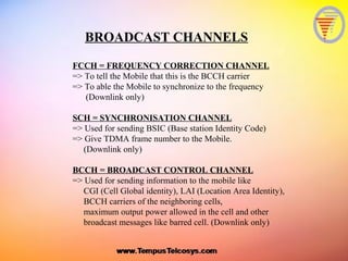


![MOBILE STATIONS ISDN NUMBER (MSISDN)
=> Is the mobile number used in a GSM PLMN (Public Land Mobile Network)
MSISDN = Country Code + National Destination Code + Subscriber number
e.x. 63 + 0918 + 8889999
Maximum length is 15 digits.
INTERNATIONAL MOBILE SUBSCRIBER IDENTITY (IMSI)
=> Is the subscriber number used over radio path for all signaling in the GSM PLMN.
This number is stored in SIM (Subscriber Identity Module), HLR (Home Location Register,
and VLR (Visitor Location Register).
IMSI = MCC + MNC + MSIN
= Mobile Country Code + Mobile Network Code + Mobile Identification Number
[ 3 digit ] [ 2 digit ] [ 11 digit ]
e.x. 502 + 19 + 2345451
TEMPORARY MOBILE SUBSCRIBER IDENTITY (TMSI)
=> Is used for the subscriber's confidentiality. Since the TMSI has only local significance
(within MSC/VLR) the structure of the TMSI can be chosen by the Vendor.
But the size must be 1/2 of the size of IMSI. Each time a mobile request for location
updating or call setup, MSC/VLR allocates to the IMSI a new TMSI, so the TMSI
is used on the signaling path, protecting the IMSI identity. Plus since the TMSI is half
the size of IMSI, we can page twice the amount compared to IMSI.](https://image.slidesharecdn.com/basicgsm-130621021755-phpapp01/85/BASIC-GSM-13-320.jpg)
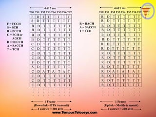
![LOCATION AREA IDENTITY (LAI)
=> Is used to uniquely identify each location area in the GSM PLMN. When the system
receives an incoming call it knows in which location area it should page the mobile
and does not page the entire network.
LAI = MCC + MNC + LAC
Mobile Country Code + Mobile Network Code + Location Area Code
[ 3 digit ] [ 2 digit ] [ 1 to 65 536 ]
e.x. = 502 + 20 + 60001
CELL GLOBAL IDENTITY (CGI)
=> Is used for cell identification within the GSM network.
LAI = MCC + MNC + LAC + CI
Mobile Country Code + Mobile Network Code + Location Area Code + Cell Identity
[ 3 digit ] [ 2 digit ] [ 1 to 65 536 ] [ 1 to 65 536 ]
e.x. = 502 + 20 + 60001 + 50001
BASE STATION IDENTITY CODE (BSIC)
=> Is used to distinguish co channel Frequency used in the neighboring cell.
BSIC = NCC + BCC
Network Color Code + Base Station Color Code
[ 1 to 7 ] [ 1 to 7 ]](https://image.slidesharecdn.com/basicgsm-130621021755-phpapp01/85/BASIC-GSM-14-320.jpg)
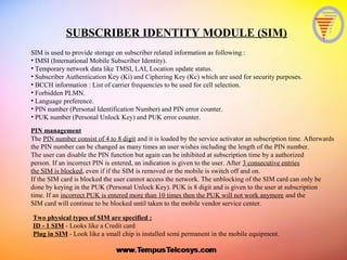

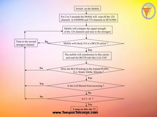
![Once the mobile is switched on and the registered home PLMN was selected (e.x. SMART), it will next
search for a BCCH frequency list, stored in its memory or in its SIM card. The list can have up to
32 BCCH frequencies for the mobile to scan. This reduces the time of cell selection, compared to
scanning the whole frequency band. If this feature is turned off at the switch then the mobile has to scan
the entire frequency band for the strongest BCCH carrier.
The BCCH frequency list is called BA (BCCH Allocation) list and there are 2 types, Active and Idle.
Idle is a list of BCCH used for scanning when the mobile is in an idle mode and Active is a list of BCCH
used during mobile busy mode. Why 2 List ???
When the mobile is in idle mode it may want to scan a longer list of BCCH and tune to the strongest
whereas when in Active mode the list of BCCH should be shorter (correspond to defined neighbors) so
that the mobile will scan the short list and get a more accurate signal strength measurements to achieve
better handover performance. It is also to reduce the time spend by the mobile to decode the BSIC.
Recommendation : ACTIVE MODE LIST SHOULD NOT BE MORE THAN 15 BCCH
FREQUENCIES.
If there is no BA list stored in the Mobile or SIM card then the mobile will scan all the 124 GSM
channels and 374 DCS channel and arrange the frequencies in a DESCENDING order of signal
strength. It will take the mobile 3 to 5 seconds to scan the whole band. After which it will tune to the
strongest frequency. The mobile will check if this is a BCCH carrier by looking out for the frequency
correction burst send by the FCCH (Frequency Correction Channel). If it is the BCCH carrier than
mobile tunes to this carrier to read the SCH (Synchronization Channel) for the BSIC parameter.
Next it will read the BCCH for system information like CGI (Cell Global identity), LAI (Location
Area Identity), BCCH carriers of the neighboring cells (BA List), maximum output power
allowed in the cell and other broadcast messages like barred cell.
[Continues …]
CELL SELECTION](https://image.slidesharecdn.com/basicgsm-130621021755-phpapp01/85/BASIC-GSM-18-320.jpg)


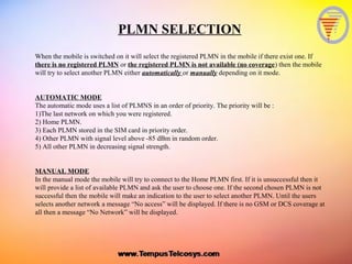
![CELL RESELECTION
After the cell has been successfully selected, the mobile now will start reselection tasks. It will continuously
make measurements on its neighboring cells (as indicated by the BA list) to initiate cell reselection if
necessary. At least 5 measurement sample per neighboring cell is needed. A running average of the
received signal level will be maintained for each carrier in the BA list.
All system information messages sent on the current BCCH on the serving cell must be read by the mobile
every 30 seconds to monitor changes in cell parameters (ex: MsTxPwrMax). The mobile also has to read the
6 strongest BCCH every 5 minutes to receive its cell parameters (ex: MsTxPwrMax). The 6 strongest can be
seen from the BA list which has the updated measurement of the 32 BCCH carrier. The neighboring list for
the best 6 neighbors is updated every 60 seconds, which means the mobile has to measure each neighbor by
10 seconds. The mobile also has to read the BSIC of the 6 strongest BCCH every 30 seconds to confirm that
it is still monitoring the same cells. If a new BSIC is detected, then the BCCH of this BSIC will be read to
receive the cell parameters.
-
Every 30 secs Every 5 minute
Every 30 secs
BSIC BCCH
Serving cell
Six neighbors
[Continues …]
1) Perform Cell reselection measurement first](https://image.slidesharecdn.com/basicgsm-130621021755-phpapp01/85/BASIC-GSM-26-320.jpg)
![The mobile will reselect and camp on another cell if any of the following criteria is satisfied :
a) The serving cell is barred.
b) C1 value in the current cell is below 0 for 5 seconds which indicates that the path loss is high and the
mobile needs to change cell.
c) The Mobile has unsuccessfully tried to access the network as defined by the MAXRET (Ericsson) parameter
or MaxNumberRetransmissions (Nokia).
MAXRET is the maximum number of retransmission a mobile can do when it is accessing the system
It is defined per cell.
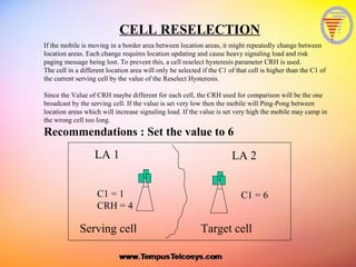
CELL RESELECTION
2) Cell reselection Criteria :
Assuming that one of the criteria above was satisfied then the mobile
will select a cell with a better C1.
However if the cell belongs to a different location area then the C1 for
that cell has to exceed a reselection hysterisis parameter called CRH
(Ericsson) or CellReselectHyseteris (Nokia) for the reselection to happen !!
[Continues …]](https://image.slidesharecdn.com/basicgsm-130621021755-phpapp01/85/BASIC-GSM-27-320.jpg)

The document provides a detailed description of GSM (Global System for Mobile Communications) technologies, including technical specifications for various channels and methods used for communication, such as TDMA (Time Division Multiple Access) and FDMA (Frequency Division Multiple Access). It outlines key elements like logical channels, subscriber identity management, mobile number formats, and procedures for cell selection and reselection in mobile networks. Additionally, it explains the roles of different channels for managing and transmitting data, ensuring mobile access and security, and facilitating communication within the GSM framework.


![10 gsm bss network kpi (uplink downlink balance) optimization manual[1].doc](https://cdn.slidesharecdn.com/ss_thumbnails/10gsmbssnetworkkpiuplink-downlinkbalanceoptimizationmanual1-140618022209-phpapp01-thumbnail.jpg?width=640&height=640&fit=bounds)


